Ultrasonic Gas Flow Meters

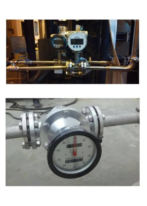
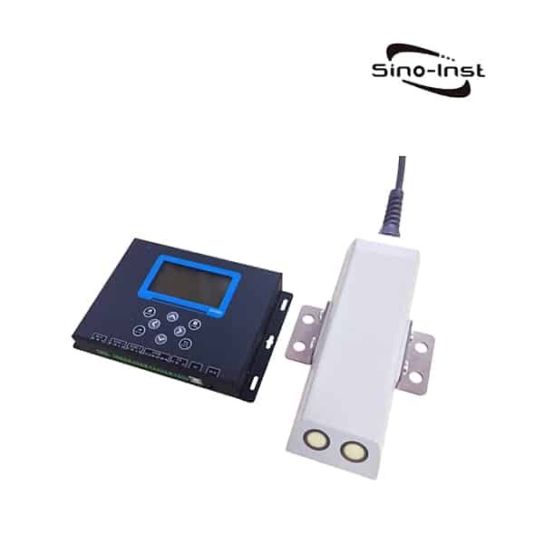
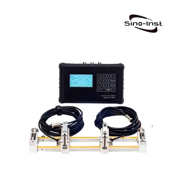
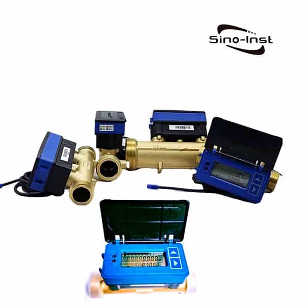
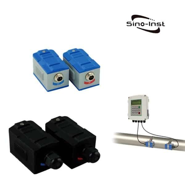
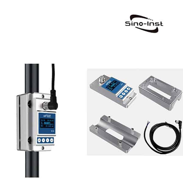
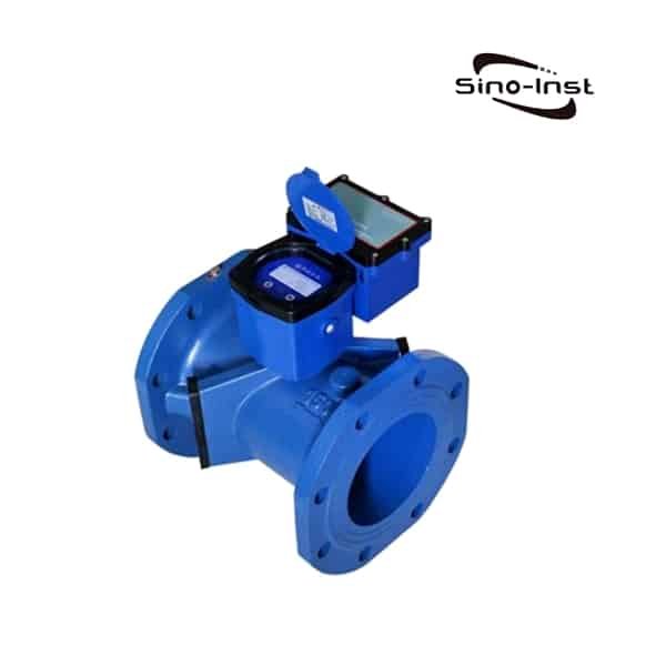
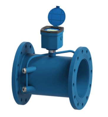
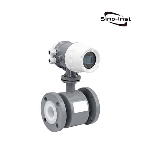
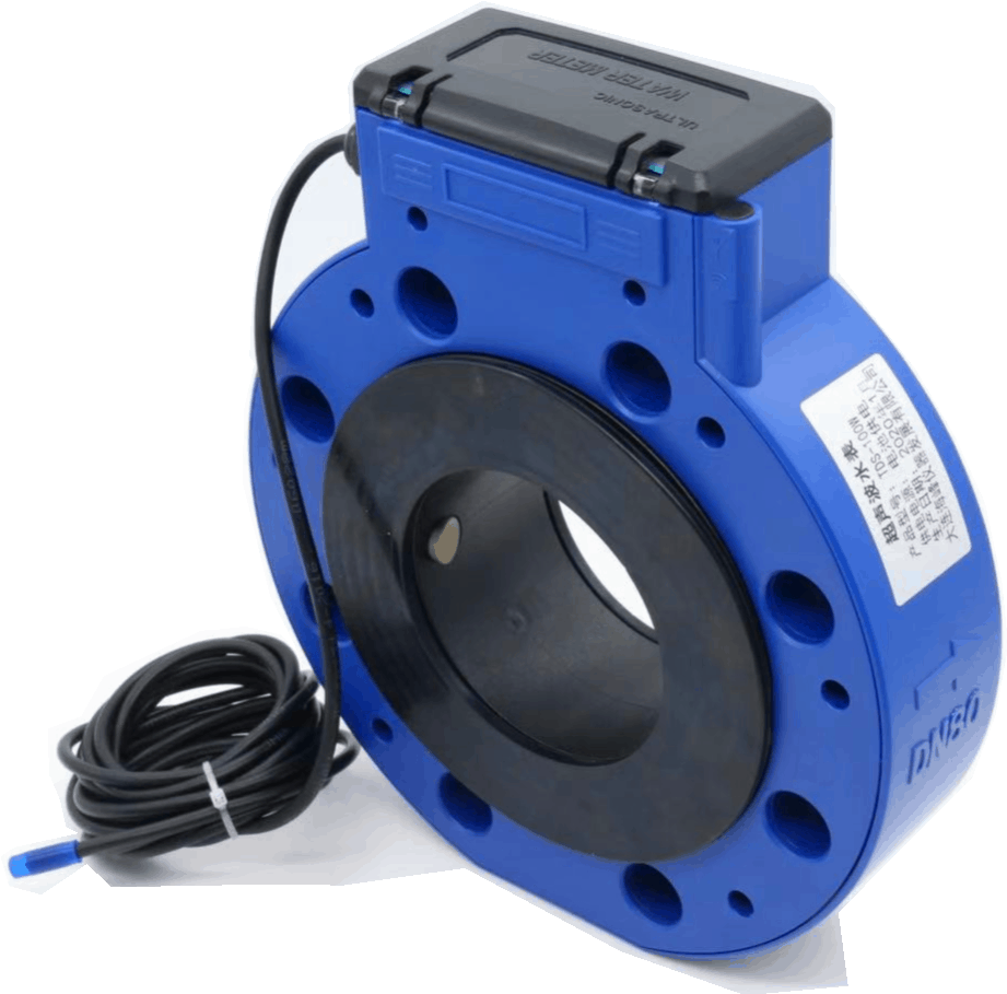
Ultrasonic Gas Flow Meter uses the principle of measuring the transit time of ultrasonic waves in the pipeline. Ultrasonic Gas Flow Meter is an ideal choice for various gas measurements.

Ultrasonic Gas Flow Meters

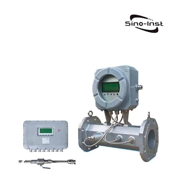
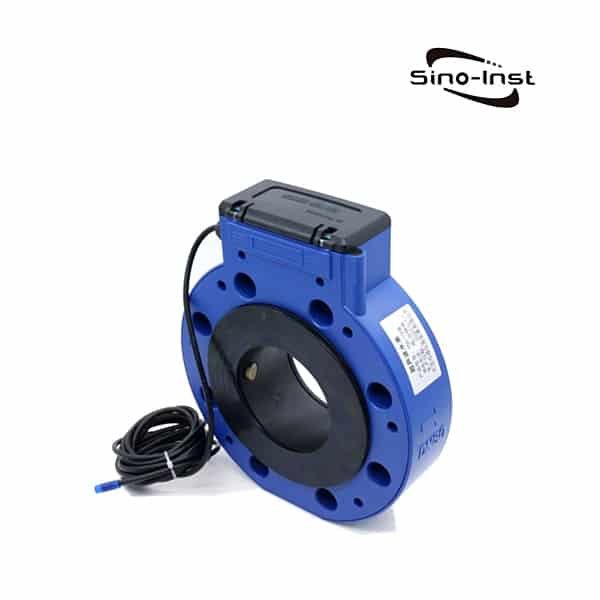
The gas ultrasonic flowmeter is suitable for blast furnace gas, converter gas, coke oven gas, mixed gas, gas, compressed air, chlorine, nitrogen and other industrial gases. Suitable for large-caliber gas measurement, suitable for low flow rate, pulsating flow gas measurement. It has the advantages of not being affected by gas components, dirt resistance, fast response, wide range, high precision, good stability, and less maintenance.

Sino-Inst offers a variety of  flow meters for flow measurement. If you have any questions, please contact our sales engineers.

Ultrasonic Gas Flow Meter Introduction

The ultrasonic gas flow meter is designed and manufactured according to the national standard GB/T-18604-2014 and the verification regulation JJG-1030-2007 using the principle of ultrasonic time difference method. Also refer to the US AGA8/AGA9/AGA10 report. Various performance indicators have reached the international advanced level of gas measurement.

Compared with traditional flow meters, gas ultrasonic flow meters have no pressure loss, strong anti-interference ability, wide range ratio, can measure small flow, can measure bidirectional flow and pulsating flow, and have the characteristics of being independent of gas composition. It is a new type of flow meter with excellent performance.

Features and advantages of Ultrasonic Gas Flow Meter

  • Suitable for multi-component metering. Gas flow measurement is not affected by changes in composition.
  • It can measure small flow and solve the problem of low flow gas measurement.
  • Large turndown ratio meets the measurement requirements of high flow rate and low flow rate.
  • Pulsating flow can be measured.
  • It can be measured in both directions.
  • Can measure dirty gas containing impurities and moisture;
  • Corrosion resistant, can measure corrosive gas flow.
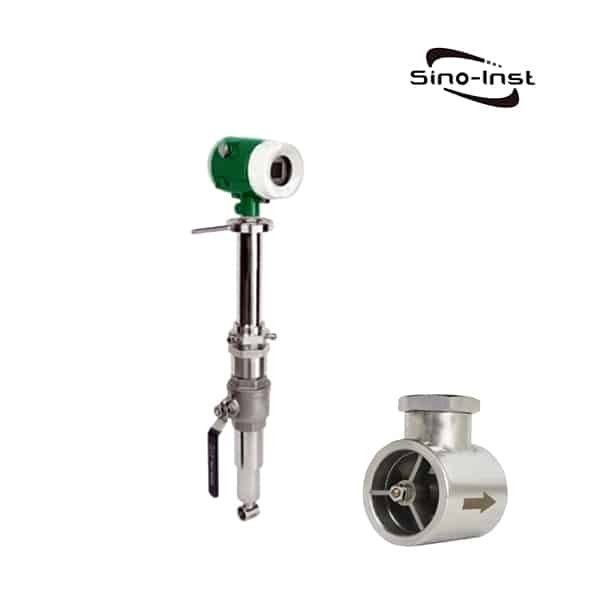
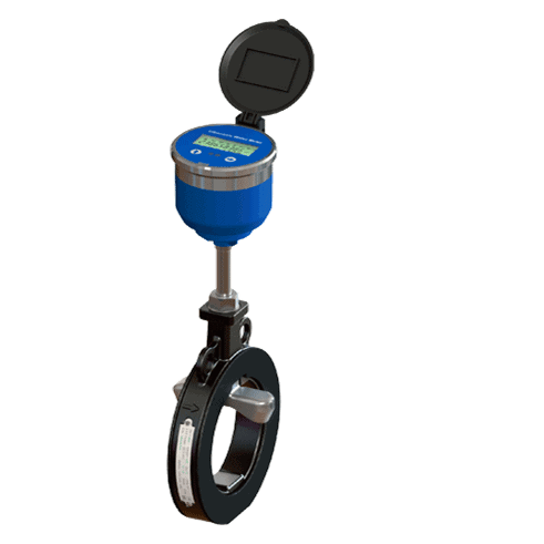
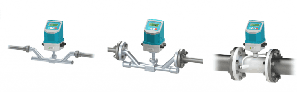
  • It can be installed online and maintained online.
  1. It adopts industrial design and the flowmeter has no moving parts. No pressure loss, reducing product use and maintenance costs.
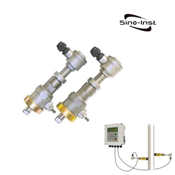
  2. It adopts all-metal transducer, which is resistant to dirt and corrosion. With a unique algorithm, it can ensure the gas flow measurement in the dirty medium.
  3. Supports intelligent alarms such as pressure, temperature, flow, and ultrasonic signals. It can realize the early warning of the ultrasonic transducer before maintenance is required. Reduce maintenance frequency. Reduce maintenance costs.
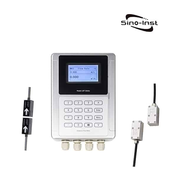
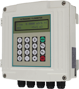
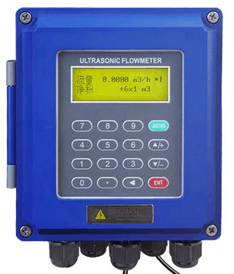
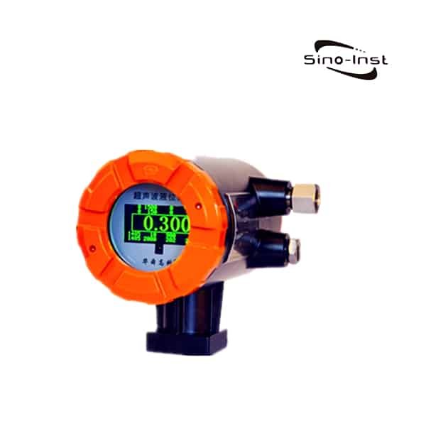
  4. Visual waveform display, menu-based instrument interface. It is convenient to use and debug the instrument.

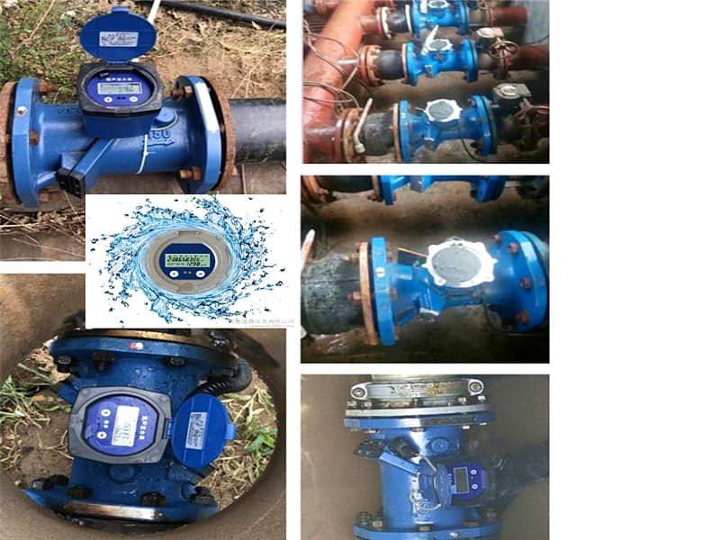
Ultrasonic Gas Flow Meter Applications

  • Gas (coke oven gas, blast furnace gas, converter gas, producer gas, blue coal gas) and other gases measurement;
  • Gas measurement of biogas, bio-fermentation gas, biomass gas, landfill gas, aeration of water treatment plants, etc.;
  • Measurement of exhaust gases such as flare gas, flue gas, exhaust gas, exhaust gas, tail gas, etc.;
  • Measurement of non-corrosive gases such as air, oxygen, nitrogen, argon, helium, etc.;
  • Metering of natural gas, liquefied petroleum gas, coal bed methane, oil and gas, mine gas, wellhead gas and other gases;
  • Metering of chemical gases such as hydrogen, acetylene and ammonia;

Read more about: Liquid Ultrasonic flow meters types & technical guide

Ultrasonic Gas Flow Meter Measuring principle

The ultrasonic flowmeter is realized by measuring the propagation time of ultrasonic waves in the pipeline. The gas flow rate is obtained by the flow velocity, the cross-sectional area of the pipe and the Reynolds number.

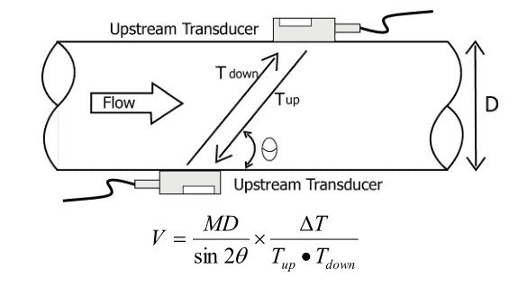
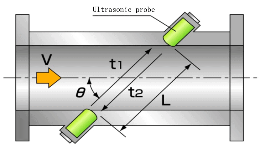
Ultrasonic flow meters use the sound wave propagation velocity method to measure the flow rate by calculating the time difference. Assuming: the sound velocity when the fluid is at rest is c, and the fluid velocity is v, then the propagation velocity in the forward flow is c+vcosθ, and the propagation velocity in the reverse flow is c-vcosθ.

Set up two ultrasonic generators (also receivers) T1 and T2 in the fluid, the distance between T1 and T2 is L, the time from T1 to T2 is t1, the time from T2 to T1 is t2, and the diameter is D , The angle between the ultrasonic transmission axis and the central axis is θ, and the time difference between the forward and reverse directions is △t=t2-t1.

L: Ultrasonic sensor distance
C: Speed of sound
V: average flow velocity
θ: Ultrasonic transmission shaft and measuring tube
The angle of the central axis
t1: Ultrasonic propagation time (downstream)
t2: Ultrasonic transmission time (backflow)
Q: Flow
A: Cross-sectional area
K: correction factor

According to the above settings:
Suppose the travel time in the forward direction is t1, and the travel time in the reverse direction is t2.

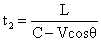
Take the reciprocal of its propagation time as the difference, namely:

Can eliminate the speed of sound term C:

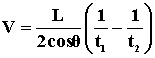
The “reciprocal difference of propagation time” method with superior repeatability: it is not affected by changes in the speed of sound (temperature), the measurement object is only time, and there is almost no change in year-round use.

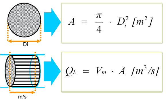
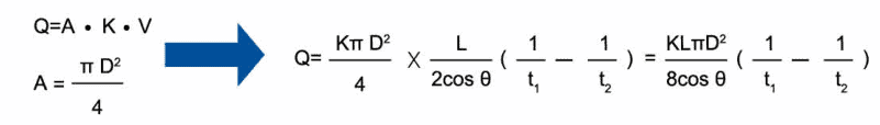
Flow rate is related to fluid velocity and cross-sectional area:

Flow rate = velocity * cross-sectional area

After correction by the flow correction coefficient, the flow can be calculated as follows:

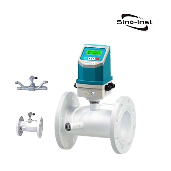
Sino-Inst’s Ultrasonic Gas Flow Meter offer reliable and accurate volume flow measurement in a large range of sizes and pressure rating while being fully compliant with international standards.

Sino-Inst is the risk-free choice for your gas flow measurement applications.

Sino-Inst’s Ultrasonic Gas Flow Meter, made in China, Having good Quality, With better price. Our flow measurement instruments are widely used in China, India, Pakistan, US, and other countries.

Turbine Flow meter Vs Gear Flow meter

When you need to measure oil flow, do you also encounter a problem: Turbine Flow meter Vs Gear Flow meter? How to choose?

Turbine flow meters and gear flow meters are commonly used flow meters. Although there is only one word difference literally, there are still different essential differences between the two.

Turbine Flow meter

Turbine flow meters are velocity flow meters, also called impeller flow meters. Can be used to measure the instantaneous flow and cumulative flow of liquids and gases.

Turbine flowmeters are widely used in flow measurement: petroleum, organic liquids, inorganic liquids, liquefied gas, natural gas, coal gas and cryogenic fluids. Turbine flowmeter signals can be divided into pulse signals or current signals (4-20mA). It is suitable for use with secondary display, PLC, DCS and other computer control systems.

Know more about: Turbine type Flow Meter for Liquid & Gas technology

Gear Flow meter

Oval gear flowmeter is a precision instrument used to measure liquid flow. It is a direct reading cumulative meter. It is a positive displacement flow meter that measures the sum of the liquid flow through the pipeline.

The oval gear flowmeter can choose two counting mechanisms: mechanical display meter and electronic display meter. The display meter has the functions of displaying cumulative flow, instantaneous flow, and zero return. It can realize on-site display and remote control.

For different measuring media (acid, alkali, organic liquid, oil, food, etc.), the flowmeter can be made of different materials (cast steel, stainless steel, and 316). It is suitable for flow measurement in chemical, petroleum, pharmaceutical, electric power, metallurgy, and food industries. Extended reading: Cylinder Gear flow meter for micro flow measurement.

Read more about Everything You Need To Know About Electronic Flow Meters

Let’s sort it out for everyone:

Turbine Flow meter Vs Gear Flow meter

1. Different measurement principles:

The liquid turbine flowmeter is a velocity flowmeter. The accuracy is 0.5%, which can be improved to 0.2%. The material of the watch body is generally stainless steel. According to site requirements, explosion-proof products can be made.

Oval gear flowmeter is a positive displacement flowmeter. The accuracy is 0.5%. Oval gear flowmeter is a purely mechanical mechanism. When the rotor of the flowmeter rotates, it drives the rotation of the counter to generate a cumulative total. Oval gear flowmeters are especially popular on occasions where explosion-proof requirements are relatively high.

2. Requirements of the working pressure:

The working pressure of the oval gear flowmeter is generally not large, 1.6Mpa. Using cast steel material, it can reach 2.5Mpa.

In contrast, turbine flowmeters are easier to make into high-pressure products. The maximum pressure of the high-pressure turbine flowmeter can reach over 25Mpa.

Requirements for low working pressure:

Turbine flowmeter does not have much requirement for the low working pressure in the pipeline, basically, it can be measured when the medium flows through it.

However, oval gear flow meters have higher requirements for small working pressures. Because of the different calibers, the pressure required to push the flowmeter rotor to work is different. The small working pressure required from small diameter to large diameter is between 0.3~0.8Mpa.

Extended reading: Positive displacement flow meter working principle

3. The influence of working temperature:

The maximum working temperature of the turbine flowmeter is 120°C. The maximum working temperature of the oval gear flowmeter is 160℃.

4. The difference of applicable media:

Water, solvents, light oils, etc. can be well suited for liquid turbine flow meters, but media with too high viscosity are not suitable.

The elliptical gear flowmeter is generally suitable for oily media. The viscosity of the applicable medium is higher than that of the turbine flowmeter. The greater the viscosity of the medium, the higher the accuracy.

For some corrosive media, both types of flowmeters can partially measure.

But the stainless steel oval gear flowmeter is not cost-effective. And for water and some electrolyte solutions, oval gear flow meters cannot be used. Because the internal mechanical parts are easily damaged by water.

Extended reading: Turbine flow meter Applications

Turbine Flow Meter Application Case: Demineralized Water.

5. Requirements on the installation site:

As a positive displacement flowmeter, the elliptical gear flowmeter has relatively low requirements for the straight pipe sections before and after and basically has no requirements for straight pipe sections.

The turbine flowmeter, as a velocity flowmeter, has higher requirements for the front and rear straight pipe sections. Especially for some small diameter turbine flowmeters, a corresponding straight pipe section must be matched.

Extended reading: Turbine Insertion Flow Meter for Large Diameter Pipeline

6. The difference between display and signal output:

The mechanical meter head of the oval gear flowmeter displays the cumulative amount. To display the instantaneous flow, you need to output a signal, and the matching secondary instrument displays the instantaneous flow value.

Turbine flowmeter can display instantaneous flow and accumulated flow on-site, and can also output with the remote signal.

7. The problem of maintaining accuracy:

The accuracy of turbine flow meters and oval gear flow meters cannot be maintained for a long time. In order to maintain the accuracy of the flowmeter, it must be calibrated regularly.

You may need to measure the flow of lubricating oil, diesel, fuel, hydraulic oil, etc.
Combine the above points and your requirements. You should be able to decide which flow meter to choose. If you still have technical questions, please contact our sales engineers in time.

Extended reading:
What is the K-factor in a flow meter?
Cryogenic Flow Meters|Liquid Nitrogen-Liquid Oxygen-LNG fluids

Turbine Flow Meter Specification

Product Name:Liquid Turbine Flowmeter
Measuring medium:water, oil, alcohol and other liquids (viscosity <5×10⁻⁶M2/S)
Diameter range:DN4~DN200 (DN4~80 commonly used thread connection)
Accuracy class:±1%R; ±0.5%R; ±0.2%R (special customization)
Output signal:square wave pulse (voltage type), 4-20MA, 0-5V (intelligent type)
Operating environment:-20℃~+60℃; 5%~90%RH
Connection method:external/internal thread, flange, clamp
Communication method:RS485 communication MODBUS-RTU (intelligent type)
Body material:stainless steel 1CR18NI9TI, 316L (hygienic type)
Protection class:IP65 (ordinary type); IP68 (special custom)

Turbine Flow meter Vs Gear Flow meter working principle

About the working principle of Turbine Flow meter Vs Gear Flow meter. I think the following video provides a good explanation. let’s look at it together:

Turbine Flow Meter Advantages and Disadvantages

Advantages:

  1. High precision. Generally up to ±1%R, ±0.5%R.
  2. Output pulse frequency signal. It is suitable for total measurement and connection with computer. No zero drift, strong anti-interference ability.
  3. The structure is compact and lightweight. Easy installation and maintenance. Great flow capacity.
  4. Good repeatability, short-term repeatability can reach 0.05~0.2%. It is because of good repeatability. Frequent calibration or in-line calibration results in extremely high accuracy.
  5. There are many types of special sensors. It can be specially designed according to user needs. Such as: low temperature type, bidirectional, downhole type, special type for sand mixing, etc.
  6. The pressure compensation can be performed under the stable pressure state of the measured gas.
  7. The range is wide, the medium and large diameters can reach 1:20, and the small diameters are 1:10.

Disadvantages:

  1. Regular calibration is required. There is no way to maintain accuracy for long periods of time. Cannot work continuously for a long time.
  2. Higher requirements for the cleanliness of the medium. But filters can be installed.
  3. The flowmeter is greatly affected by the flow velocity distribution of the incoming flow (a flow regulator can be installed).
  4. It is not suitable for places where the flow rate changes rapidly.
  5. Not suitable for testing corrosive media.

Turbine Type Flow Meter Installation Guidelines

In order to ensure the accurate measurement of the turbine flowmeter, the installation location and method must be selected correctly.

  1. Requirements for straight pipe sections:
    • The flowmeter must be installed horizontally on the pipeline (the inclination of the pipeline is within 50), the axis of the flowmeter should be concentric with the axis of the pipeline during installation, and the flow direction should be consistent.
    • The length of the upstream pipeline of the flowmeter should have an equal diameter straight pipe section of not less than 2D. If the installation site is allowed, it is recommended that the upstream straight pipe section is 20D and the downstream is 5D.
  1. Requirements for piping:
    The inner diameter of the upstream and downstream piping at the installation point of the flowmeter is the same as the inner diameter of the flowmeter.
  2. Requirements for bypass pipes:
    In order to ensure that the normal use of the medium is not affected during the maintenance of the flowmeter, a cut-off valve (stop valve) should be installed on the front and rear pipelines of the flowmeter, and a bypass pipeline should be set at the same time. The flow control valve should be installed downstream of the flowmeter. When the flowmeter is used, the shut-off valve installed upstream must be fully opened to avoid unstable flow of the fluid in the upstream part.
  3. Requirements for the external environment:
    The turbine flowmeter is best installed indoors. When it must be installed outdoors, sun protection, rain protection and lightning protection measures must be adopted to avoid affecting the service life.
  4. Requirements for impurities contained in the medium:
    In order to ensure the service life of the flowmeter, a filter should be installed before the straight pipe section of the flowmeter.
  5. Installation site:
    The flowmeter should be installed in a place that is easy to maintain and free from strong electromagnetic interference and heat radiation
  6. Requirements for installation and welding:
    The user can configure a pair of standard flanges to be welded on the front and rear pipes. Welding with flow meter is not allowed!
    Before installing the flowmeter, the welding slag and other dirt in the pipeline should be strictly removed. To ensure that the flowmeter is not damaged during use.

Frequently
Asked
Questions

If the flowmeter is divided into 5 categories. Then the five commonly used flowmeters are:

  1. Electromagnetic flowmeter
  2. Differential pressure flowmeter
  3. Turbine flowmeter
  4. Ultrasonic flowmeter
  5. Volumetric flowmeter (PD)

For liquids, it is generally ±0.25%R-±0.5%R,
High precision type can reach ±0.15%R;

And the medium is gas, generally ±1%R-±1.5%R;
The special type is ±0.5%R-±1%R.

Turbine flowmeter is the main type of velocity flowmeter. It uses a multi-blade rotor (turbine) to sense the average flow rate of the fluid, and derives the flow or total amount of the meter.

More abou: More Details About Turbine Flow Meter

For different working principle, We offer different types of flow meters, like:

  • Differential Pressure Flow Meters
  • Orifice Plate
  • Venturi Tube
  • Flow Nozzles
  • The Sonic Nozzle – Critical (Choked) Flow Nozzle
  • Calorimetric Flowmeter
  • Ultrasonic Doppler Flowmeter
  • Positive Displacement Flowmeter
  • Variable Area Flowmeter or Rotameter
  • Velocity Flowmeters
  • Pitot Tubes
  • Electromagnetic Flowmeter
  • Turbine Flowmeter
  • Vortex Flow Meter
  • Thermal Flowmeter
  • Coriolis Flowmeter
  • Mass Flowmeters
  • Open Channel Flowmeters

Turbine flowmeters are widely used in the following measurement objects:
Petroleum, organic liquids, inorganic liquids, liquefied gases, natural gas, natural gas and cryogenic fluids.

Transshipment and centralized transportation stations for liquefied petroleum gas, refined oil and light crude oil abroad. The first and second stations of large crude oil pipelines are widely used for trade settlement.

More Flow Measurement Solutions

Flow Pressure Transducers for Fluid Pipelines

Flow Pressure Transducers are measurements of fluid pressure within a pipeline. When fluid flows through a pipe, pressure acts on the pipe wall. The medium in the pipeline can be…

Crude Oil Flow Meter

Crude Oil Flow Meter refers to a type of flow meter that can accurately monitor and measure the flow of crude oil. Crude oil is an industrial raw material with…

Non Contact Flow Meters Measure Liquid Flow

What is non contact flow meter? Non Contact Flow Meters refers to flow meters that can achieve flow measurement without contacting the fluid medium. No need to destroy the pipeline…

Mechanical Oil Flow Meters

What is mechanical oil flow meter? Mechanical oil flow meter refers to a flowmeter that can detect the volume flow of oil inline. Most importantly, this type of flowmeter is…

Clamp on Water Flow Meter

What is Clamp on Water Flow Meter? Clamp on Water Flow Meter is also known as the clamp-on ultrasonic flowmeter. Using an ultrasonic flowmeter to measure water flow rate is…

Kerosene Gasoline/ Kerosene Flow Meter

A kerosene flow meter is a flow meter that can be used to measure the flow of kerosene. Kerosene is a common oil in industrial production. It is an organic…

Slurry Flow Meter

Flow Meter for Slurry Application Slurry is a product of domestic sewage and industrial wastewater treatment. Slurry consists of solid impurities, a slurry of suspended substances. The main characteristic of…

Measuring Steam Flow and Steam Flow Meters

Measuring Steam Flow Measuring Steam Flow is a difficult task. But again, it’s a very important thing. Steam flow measurement is difficult, the main reason is determined by the characteristics…

This article “Turbine Flow meter Vs Gear Flow meter”, Sino-Inst provides you. Please indicate the source!

Sino-Inst, Manufacturer for Turbine Flow meter & Gear Flowmeters, like gas turbine flow meter, liquid turbine flow meter, sanitary turbine flow meter, insertion turbine flow meter, steam turbine flow meter, and natural gas turbine flow meter.

Sino-Inst’s Turbine Flow meter & Gear Flow meter, made in China, Having good Quality, With better price. Our flow measurement instruments are widely used in China, India, Pakistan, the US, and other countries.

Portable Doppler Flow Meter

The Portable Doppler Flow Meter uses the Doppler effect of sound waves propagating in the fluid. Hand-held design, suitable for handheld wading water flow measurement.

The Portable Doppler Flow Meter (Model: LSX-2) can obtain the velocity of the fluid by measuring the Doppler frequency shift of the sound waves scattered by the moving particles in the fluid. Combined with the built-in pressure water level gauge, the velocity area method can be used to measure the flow of the liquid. It is suitable for flow measurement of open channels, rivers, pipelines and difficult-to-build standard sections. It can work continuously for more than 12 hours on a single charge.

Sino-Inst offers a variety of  Ultrasonic flow meters for flow measurement. If you have any questions, please contact our sales engineers.

Features of Portable Doppler Flow Meter

  • The flow rate range can reach 0.02-5m/s, and the resolution is 1mm/s.
  • High response time. It takes a long time to get the flow rate and the measurement results are refreshed in real time.
  • Flow measurement by velocity area method, suitable for full and non-full pipes. The water level relationship of the section can be set freely.
  • The integrated pressure and water level sensor can directly measure the water depth and can be used in shallow water.
  • Fluid mechanics shell design. Little impact on the flow state of the water body. Does not affect the measurement accuracy.
  • Small and lightweight handheld terminal with a graphic display interface. It can display the flow rate, flow, water level, and water temperature in real time.
  • 16MB internal storage space. It can store more than 100,000 data.
  • Equipped with data receiving software. Used for data export and processing.
  • Built-in multiple standard flow rate measurement methods and flow calculation methods.
  • Rechargeable battery pack, continuous use for more than 12 hours.

Specifications of Portable Doppler Flow Meter

Fluid velocityRange20mm/s-5000mm/s
measurement accuracy±1% of measured flow rate
Resolution1mm/s
Liquid levelRange0-5m
measurement accuracy±1cm
Resolution1mm
Flow rateRange0.001m3/s to 9999m3/s depends on the actual section
measurement accuracy±3%
Resolution0.0001m3/s
Other parametersPower supply rangeBuilt-in rechargeable battery, fully charged for more than 12 hours
Collection cycle5 meters, 10 meters optional
Interface TypeUSB
Storage temperature-20-80℃
Operating temperature0-60℃
Protection levelIP68
shell materialPVC

Extended reading: Make Ultrasonic Open Channel Flow Meter Work for You

Portable Doppler Flow Meter to measure open channel flow

Portable Doppler ultrasonic open channel flowmeter uses the principle of Doppler velocity area method to monitor flow. It is designed for flow velocity and flow measurement in open channels and partially filled pipes.

The principle of the Portable Doppler Flow Meter is to measure the fluid flow rate using the ultrasonic Doppler principle.

The liquid level is measured by pressure and ultrasonic sensors. The calculator can set multiple point coordinates to simulate the shape of the weir trough to obtain the cross-sectional area, so as to measure and monitor the flow.

The principle of ultrasonic Doppler is adopted, that is, any liquid flowing in the pipeline has discontinuous disturbance.

These discontinuous disturbances can be suspended solid particles or bubbles, or interfaces caused by fluid disturbances.

This disturbance causes the reflected ultrasonic wave to produce a Doppler frequency shift Δf. The Doppler shift Δf is a linear function of the flow velocity. By measuring the Doppler frequency shift Δf, and according to the propagation speed of sound waves in the water. The flow velocity of the disturbance can be calculated, and then the water flow velocity can be obtained.

Only need to connect the flowmeter probe and the handheld controller when using the equipment.

Use the measuring rod to fix the flowmeter probe.

Put the flowmeter probe into the channel or water body to be measured.

The hand-held controller can display the corresponding flow rate information.

How much is a 2 inch water flow meter? Let’s find out.

Portable transit time flow meter

Handheld Ultrasonic Flow Meter ( Model:2000H) has been successfully applied to measurement work in various industries. The measuring range is 20-6000mm (0.5-20 inches). A non-contact measurement method is adopted. Flexible operation and easy to carry. Conductive or non-conductive, corrosive or non-corrosive liquids can be measured. Various fluids: water, pure water, sewage, sea water, chemical fluids, river water, fuel Oil etc. can be measured.

Sino-Inst, Manufacuturer for Portable Doppler Flow Meters. It can measure a single sound-conducting liquid medium. It can measure even liquids such as water, sea water, oil, and slurry.

Sino-Inst’s Portable Doppler Flow Meter, made in China, Having good Quality, With better price. Our flow measurement instruments are widely used in China, India, Pakistan, US, and other countries.

Request a Quote

Please enable JavaScript in your browser to submit the form

Wall Mounted Ultrasonic Doppler Flow Meter

What is a Doppler flow meter? Doppler Flow Meter is a flow meter that uses the doppler effect principle to monitor the liquid flow rate.

Doppler Flow meter use reflected ultrasonic sound to measure the fluid velocity. By measuring the Doppler frequency shift of the sound waves scattered by the moving particles in the fluid, the velocity of the fluid can be obtained. Combined with the built-in pressure water level gauge. Using the velocity area method. The flow of liquid can be measured. Suitable for flow measurement in open channels, rivers, and various full and partial open channels.

Sino-Inst offers a variety of  Ultrasonic flow meters for flow measurement. If you have any questions, please contact our sales engineers.

Features of Doppler Flow Meter

  • All functions in one design. Simultaneous measurement of average flow rate, water depth, and water temperature
  • The velocity area method is used to measure the flow, and there is no head loss. There is no need to build a standard weir.
  • The ultrasonic Doppler principle is used to measure the flow velocity. The measurement accuracy is high and the initial speed is low.
  • No mechanical rotor structure. It has no effect on the water flow state, and the measurement is more accurate.
  • Comes with a temperature sensor. It can be used to compensate for the effect of water temperature on the speed of sound.
  • It can measure instantaneous flow and cumulative flow.
  • Using frequency domain Doppler analysis algorithm. The data is stable and reliable, and the real-time performance is strong.
  • Simple installation. No need for auxiliary engineering facilities

Specifications of Doppler Flow Meter

Fluid velocity Range 20mm/s-5000mm/s
measurement accuracy ±1% of measured flow rate
Resolution 1mm/s
Liquid level Range 0-5m
measurement accuracy ±1cm
Resolution 1mm
Flow rate Range 0.001m3/s to 9999m3/s depends on the actual section
measurement accuracy ±3%
Resolution 0.0001m3/s
Other parameters Power supply range 9-24V
Collection cycle Can be set
Interface Type RS485(Modbus)
Storage temperature -20-80℃
Operating temperature 0-60℃
Protection level IP68
shell material PVC

Guess You’ll Like: Ultrasonic flow meters types & technical guide

What is a Doppler flow meter?

Doppler flowmeter is an ultrasonic flowmeter that uses the Doppler effect of sound waves propagating in fluids. It is suitable for the flow measurement of open channels, rivers and difficult-to-build standard sections, as well as the flow measurement of various full and partial open channels.

The Doppler flowmeter uses the principle of ultrasonic Doppler to measure. By measuring the Doppler frequency shift of the sound waves scattered by the moving particles in the fluid, the velocity of the fluid can be obtained. Combined with the built-in pressure water level gauge, the velocity area method can be used to measure the flow rate of the liquid.
According to different application scenarios, it can be called river flowmeter, sewer flowmeter, channel flowmeter, farmland irrigation flowmeter, non-full pipe flowmeter, etc.

Doppler flowmeters do not need to cut off the pipeline to install pipe-segment sensors like electromagnetic flowmeters. There is no need to use a shut-off device. Do not install a fixed weir to control the flow of water from a fixed outlet.

The Doppler flowmeter can measure in both clean and muddy water, and can also measure reverse flow velocity.

Read mroe about: Irrigation Flow Meters for Agriculture Water System

Doppler flow meter working principle

For flow velocity measurement, the first thing to explain is the Doppler shift. When there is relative motion between the wave source and the observer, the frequency received by the observer is different from the true frequency of the wave source. The difference between the frequency of the received signal and the frequency of the sound source is called the Doppler shift. Its size is determined by the relative speed between the two. This physical phenomenon is called the Doppler effect.

When measuring the flow velocity, the wave emitted by the probe encounters suspended matter, solid particles, vapor bubbles, and even unstable vortices and disturbances in the medium that follow the wave. Both will produce reflected waves that deviate from the transmit frequency, resulting in Doppler frequency changes. This effect is proportional to the velocity of movement of the reflector.

The receiving probe receives the reflected wave from each point. After complex signal processing, dynamic spectrum analysis and accuracy calculation. The flow velocity of the fluid in the pipe section can be obtained.

Flow rate calculation

The ultrasonic beam emitted from the Doppler velocity sensor (transducer) encounters particles or bubbles moving in the fluid. It is reflected back and received by the Doppler flow sensor (transducer). The Doppler frequency shift of the transmitted signal and the received signal is proportional to the fluid velocity.

Among them:
u is the channel flow rate,
f1 is the working frequency of the sensor,
δfd is the Doppler frequency difference.

Flow calculation

Real-time flow velocity and water level data collected by acoustic Doppler flowmeter.
The data acquisition and processing unit receives the flow rate and water level data. Calculate the instantaneous flow rate and record it as Qs;
Then calculate the accumulated flow rate and record it as Q; its flow rate can be calculated as follows:

Qs=AV

In the formula, A is the water area of the pipeline, and V is the average flow velocity of the section.

Q = QsT

In the formula, the instantaneous flow of Qs section, T is the accumulated time (unit h).

Read more about: Ultrasonic flow meters types & technical guide

Ultrasonic doppler flow meter advantages and disadvantages

Advantages of ultrasonic Doppler flowmeter:

  1. Contact measurement. Can accurately measure the flow rate of the fluid;
  2. Wide range of use. It can measure the flow velocity of rivers, channels, dissatisfied pipelines, and urban underground pipe network sewer scenarios;
  3. Simple installation. No baffle or weir groove is needed. The data can be measured by simply contacting the sensor directly with the fluid;
  4. Low power consumption, diversified power supply methods, 6v power supply. Optional external power supply, battery power supply, solar power supply;

Disadvantages of ultrasonic Doppler flowmeter:

  1. Cannot measure pressured pipelines, closed pipelines and high temperature environments;
  2. The water depth is less than 10cm and cannot be measured;
  3. The stable data can only be measured in a place where the water flow is stable, and there are certain requirements for the selection of the installation location;
  4. For a site with a large turbidity, it is not as good as a site with more floating objects, garbage, and bottom silt, and accurate data cannot be measured;

Ultrasonic Doppler Flow Meter Applications

Fixed Doppler ultrasonic flowmeters

Mainly used in environmental testing of urban sewage treatment plants, drainage pumping stations, and mining, oilfields, metallurgy, chemical, oil refining, paper, food and other industries.

Flow measurement of urban drainage, industrial wastewater, domestic sewage, mud, paper pulp, oil-water mixture, etc.

It is suitable for hard pipes such as steel and hard plastic pipes.

It can measure two-phase liquids containing suspended solid particles or bubbles in tubes with various tube diameters and wall thicknesses.

Doppler flow meter open channel

There are many monitoring methods for measuring the flow of water in open channels, among which the water level flow method and the velocity area method are the majority. The former uses an ultrasonic open channel flowmeter to measure, and the latter uses a Doppler flowmeter to measure in an open channel.

The methods used for different open channels are different. Here we mainly talk about what conditions the Doppler flowmeter must meet for measurement in an open channel.

The Doppler flowmeter is in full contact with the water through the flow rate sensor. The real-time flow rate is measured. Input the width, shape, and water depth of the open channel to the host. The host uses the speed area method to convert the real-time flow.

Therefore, it requires the water depth to immerse the sensor in order to obtain more accurate data.

Due to the principle of ultrasonic measurement, it is determined that the Doppler flowmeter measurement in the open channel needs to meet the following conditions:

  1. The flow rate of the water flow should be uniform, and there should be no plain flow (to ensure such measurement conditions, the site should meet the straight channel with 15 times the channel width)
  2. Water depth requirement: no sensor (Yuzheng Doppler flowmeter requires water depth ≥13cm)
  3. Width of open channel ≥50cm
  4. The water flow velocity is required to be 0.04m/s-10.00m/s. If the flow velocity is too fast, the measurement will be inaccurate
  5. There should be no rubbish and large floating objects in the open channel
  6. The water in the open channel should not be too pure, for example, pure water cannot be measured

The above six points are the conditions that need to be met simultaneously for the measurement in the open channel of the Doppler flowmeter. Of course, before the measurement, the selection of installation and the selection of the installation point are also very important.

If you still don’t understand the details, you can contact Sino-inst technical consultant to get in touch to solve your troubles in detail.

Extended reading: Make Ultrasonic Open Channel Flow Meter Work for You

Application of Ultrasonic Doppler Flowmeter in Irrigation District

1.Check the water level and velocity curve

Portable Doppler ultrasound can be used to place it in the channel of the irrigation area. During the upstream discharge process, the water level, velocity, and flow changes are measured. The water level, velocity, and flow meter are generated.

In the later calculation, you can directly use the ultrasonic water level gauge or the radar water level gauge for online monitoring. Combine the existing water level, velocity and flow relationship to get the flow value under the current water level.

When the upstream and downstream channels of the irrigation area are changed, re-measurement is required. This method is suitable for use in irrigation areas that require cost and require mass monitoring.

2.Long-term online monitoring

Use LSX-1 Doppler ultrasonic flowmeter with telemetering terminal. Use city power or solar power system for power supply. Fix the flowmeter in the channel. The telemetry terminal periodically collects the data in the flowmeter and sends it to the server remotely via GPRS. The data can be viewed through the WEB platform.

Portable Doppler Flow Meter

The Portable Doppler Flow Meter uses the Doppler effect of sound waves propagating in the fluid. Hand-held design, suitable for handheld wading water flow measurement.

The Portable Doppler Flow Meter (Model: LSX-2) can obtain the velocity of the fluid by measuring the Doppler frequency shift of the sound waves scattered by the moving particles in the fluid. Combined with the built-in pressure water level gauge, the velocity area method can be used to measure the flow of the liquid. It is suitable for flow measurement of open channels, rivers, pipelines and difficult-to-build standard sections. It can work continuously for more than 12 hours on a single charge.

Transit time vs Doppler flow meter

There are two types of ultrasonic flowmeters, one is the time difference measurement method, and the other is the Doppler method. Many users often only know one of them.

Here, we make a simple comparison so that you can choose the correct model.

1.The measurement principle is different.

The main principle of the time difference method is that when the ultrasonic beam propagates in the liquid, the flow of the liquid will cause a small change in the propagation time. The change in its propagation time is proportional to the flow rate of the liquid.

At zero flow, the time required for the two sensors to transmit and receive sound waves is exactly the same. The only technology that can actually measure zero flow.

When the liquid is flowing, the transmission time of sound waves in the counter-current direction is longer than that in the downstream direction. The Doppler method uses the characteristic that the ultrasonic wave will be scattered when encountering tiny solid particles or bubbles in the propagation path.

2.The applicable medium is different.

The time difference ultrasonic flowmeter can only measure clean liquids. It will not work well when it contains more solid particles or bubbles.

The Doppler method uses the scattering characteristics of ultrasonic waves for measurement. Therefore, the Doppler method is suitable for measuring fluids containing solid particles or bubbles, but clean liquids cannot be measured.

3.The measurement accuracy is different.

The time difference method has higher measurement accuracy, and the Doppler method has lower measurement accuracy.

Since scattered particles or bubbles exist randomly, the sound transmission performance of the fluid is also different. If it is a fluid with poor sound transmission performance, the scattering is stronger in the low velocity area near the pipe wall.

However, the scattering of fluids with good sound transmission performance is dominant in the high velocity area, which makes the measurement accuracy of the Doppler method lower.

Although it adopts a structure in which the transmitting transducer and the receiving transducer are separated. In this way, only the scattering in the middle area of ​​the velocity profile can be received. However, the measurement accuracy is still lower compared with the time difference method.

4.The working conditions are different.

The time difference method is suitable for full pipe measurement.
The Doppler method is suitable for measuring the flow of full pipes, partial pipes, open channels, etc.

OMEGA Engineering has a good explanation of Doppler vs Transit Time. Let’s look together.

Video source: https://www.youtube.com/watch?v=NQWNYARWmB8

More Featured Ultrasonic Flowmeters

Sino-Inst, Manufacuturer for Ultrasonic Doppler Flow Meters. It can measure a single sound-conducting liquid medium. It can measure even liquids such as water, sea water, oil, and slurry.

Sino-Inst’s Ultrasonic Doppler Flow Meter, made in China, Having good Quality, With better price. Our flow measurement instruments are widely used in China, India, Pakistan, US, and other countries.

Ultrasonic Open Channel Flow Meter

Ultrasonic open channel flow meter can measure the water level, flow rate, and total volume flowing through weirs, troughs, channels, and partially filled pipes. Ultrasonic open channel flow meter is used in conjunction with Parshall flume. Using hydraulic flow measurement, ultrasonic positioning, microcomputer processing, digital display, and other technologies. It can be installed and automatically measured in harsh environments. Commonly used for agricultural irrigation water discharge measurement, wastewater, sewage, and other measurements.

Sino-Inst offers a variety of  Ultrasonic flow meters for flow measurement. If you have any questions, please contact our sales engineers.

Features of Ultrasonic Open Channel Flow Meter

  • Ultrasonic non-contact liquid level measurement does not affect the flow rate at all. Accurate liquid level measurement is an ideal level meter.
  • The probe has low power consumption, simple installation and easy positioning. It is widely used in rivers, water supply, factories, urban sewage pipelines and other related fields.
  • The flow totalizer is easy to operate and suitable for wide types of water measuring weirs, including thin-walled right-angled triangular weirs, rectangular weirs, and Parshall grooves.
  • The flow totalizer has the function of historical flow recording. It can record the flow data of the past 60 hours, 30 days, 12 months, and 10 years. More historical data can be recorded in real time through the SD card.
  • Comprehensive instrument control functions, four-way relay signal output, easy to connect to commonly used actuators (motors, alarms, etc.).
  • According to the requirements of working conditions, the probe can choose special models such as IP68, anti-corrosion, explosion-proof, small blind area high-precision, ultra-low power consumption, large range and other special models.
  • Built-in remote communication module, various communication protocols can be customized (customized when ordering).

Extended reading: Flow Totalizer Meter vs Flow Meter

Specifications of Ultrasonic Open Channel Flow Meter

StructureOne-piece and split type
Measuring range0.1m³/h~99999.99m³/h is determined according to different weirs and troughs
Cumulative flowThe maximum is: 429000000.00m3
Level measurement accuracy0.50%
Resolution3mm or 0.1% (whichever is greater)
Flow measurement accuracyStandard weirs and troughs 1~5% (weir troughs and channels that meet the requirements of the national standard),
non-standard weirs and troughs 10~50%
powered by220VAC±15% 50HZ, or 24VDC 120mA, (optional) 12VDC,
battery powered, solar powered
Protection levelDisplay instrument IP66, probe IP68
Probe selection instructionsIt is recommended to use 100KHz M48×2 probe for No.1-5 Parshall grooves,
The measuring range is 1 meter, it is not easy to hit the wall or corner of the Parshall groove to form false signals;
The probe blind area is small, only 10-13 cm, and the mounting bracket can be made lower;
It is recommended to use 64Khz M48×2 probe for No. 6-25 Parshall slot, measuring range 2 meters, blind area 30 cm.

Application of Ultrasonic Open Channel Flow Meter

Ultrasonic open channel flowmeter has a special structure with a Parshall groove. It can be used to continuously monitor the flow of sewage in the open channel and accumulate the flow. It is suitable for flow measurement under the conditions of water canal, agricultural irrigation, wastewater discharge, water conservancy, hydropower, environmental protection, and other industrial and agricultural open channels.

The open channel flowmeter transmits and receives ultrasonic waves under the control of a computer. Calculate the distance between the open channel flowmeter and the measured liquid surface according to the transmission time. So as to get the height of the liquid level.

So what problems should be paid attention to in the use of ultrasonic open channel flowmeters?

  1. The host of the ultrasonic open channel flowmeter should be installed indoors. Check lines and sensors regularly;
  2. Regularly check whether the filter screen and the still water well are blocked by foreign matter;
  3. Perform metrological verification of the instrument regularly;
  4. Regularly check the corrosion of the probe and replace it as needed

Ultrasonic open channel flowmeter has a special structure with a Parshall groove. It can be used to continuously monitor the flow of sewage in the open channel and accumulate the flow. It is used to measure the liquid flow in self-flowing partial pipes and open discharge channels. It is suitable for flow measurement under the conditions of water canal, agricultural irrigation, wastewater discharge, water conservancy, hydropower, environmental protection and other industrial and agricultural open channels.

Extended reading: Ultrasonic flow detectors types

Parshall Flume (PVC material, stainless steel material) for Open Channel Flow Meter

When choosing the type of weir and trough for measuring water, it is necessary to consider the size of the flow in the channel, the flow pattern of the water in the channel, and whether it can form a free flow. According to the different large flow, we can choose different weir grooves.

  • The large flow rate is less than 40 liters/sec. It is recommended to use a right-angled triangular weir;
  • It is recommended to use Parshall tank for more than 40 liters/sec;
  • The upstream channel is short, and the large flow rate is greater than 40 liters/sec. It is recommended to use a rectangular weir.

Conditions permit, a good choice of Parshall slot. The water level-flow relationship of the Parshall trough is calibrated by the laboratory, and the requirements for the upstream flow into the trough are relatively weak. The water level-flow relationship of the triangular weir and the rectangular weir is derived from theoretical calculations, and it is easy to cause additional errors due to ignoring some use conditions.

Use glass fiber reinforced plastic to make the measuring weir or trough. The size of the mouth of the triangular weir and the rectangular weir should be accurate, and the surface facing the water inlet should be smooth; the size of the throat part of the Parshall groove should be accurate, and the inner surface of the groove should be smooth.

Common installation methods and installation precautions of Parshall groove:

  • Put the Parshall trough into the open channel. Keep the trough level. The centerline of the Parshall trough should coincide with the centerline of the channel, so that the water flow into the Parshall trough does not appear drift.
  • After the Parshall trough is filled with water, the flow state of the water should flow freely. The submergence degree of the Parshall trough is less than the specified critical submergence degree.

Require:
Keep the downstream discharge of the Parshall trough unblocked. Do not accumulate water, if not unblocked. Keep the water level difference greater than or equal to 30MM.

The straight section before the Parshall trough has a distance buffer of 1 to 3 meters. The buffer channel should be level with the bottom of the trough. It is convenient for ultrasonic measurement.

It must be ensured that there is a water level difference downstream of the Parshall trough. The discharge is unobstructed and no water will accumulate.

Extended reading: Dam water level measurement

Open Channel Ultrasonic Flow Meter Working Principle

The open channel flowmeter is based on the specific shape of the Parshall metering groove/weir plate metering groove. It guarantees a certain liquid level and knows a certain flow rate. The Parshall groove/weir plate metering groove is selected as the specific flow channel. The measurement accuracy is high. Easy to install.

The sensor measures the height of the liquid level, which is processed by 89C52 series single-chip microcomputers to obtain the instantaneous flow and cumulative flow values.

The flow can be expressed by the following formula:
  Q=KHn
  Q: Instantaneous flow rate (t/h) K: Flow rate constant
  H: height of liquid level n: nth power value

The instantaneous flow is processed by the cumulative accumulation to obtain the cumulative flow.

Extended reading: Radar Non Contact Water Level Sensor

Inline Ultrasonic Flow Meter

Transit Time Ultrasonic Flow Meter adopts the measurement principle of the time difference method. It uses the ultrasonic wave emitted by the sensor to propagate in the flowing fluid. The sound wave propagation speed in the downstream direction will increase, and the backward direction will decrease. In the same propagation distance, there will be different transmission times. According to the difference between the transmission time and the measured The relationship between fluid velocity measures the fluid velocity.

The flow rate of the fluid is different in different positions in the tube. The flow rate in the center of the tube is faster than the flow rate near the wall of the tube. The flow velocity distribution of the fluid in the pipeline can be represented by the flow velocity cross-sectional distribution diagram.

By setting the flowmeter and considering the cross-sectional distribution of the flow velocity, the average flow velocity can be calculated. Then the volume flow of the fluid can be obtained according to the cross-sectional area of the pipe.

Notes:
V measure fluid velocity
M ultrasonic reflection times
D pipe diameter
θ The angle between the ultrasonic signal and the fluid
T up The time when the downstream sensor transmits the signal to the upstream
T down Time from the upstream sensor to downstream
ΔT = T up – T down

Guess You’ll Like: Ultrasonic flow meters types & technical guide

Ultrasonic Doppler Flow Meter uses the physical principle of Doppler frequency shift to measure the water flow velocity.

Doppler effect (Doppler frequency shift) principle:
The sound waves emitted by one object are received and reflected by another object. If the object emitting the sound wave is moving relative to the receiving object. The frequency of the sound wave received by the receiving object will be different from the frequency of the emitted sound wave.

If the relative distance between two objects is reduced, the received frequency will increase.
If the relative distance between two objects is increased, the received frequency will decrease.

Such Doppler effects often occur in daily life. For example: when you hear the sirens (sounds) of an oncoming police car. The sound will appear higher in frequency. When the police car is far away from you, the sound it hears will become lower.

Through the difference between the frequency of transmitting ultrasonic waves and the frequency of receiving ultrasonic waves, the specific flow rate can be calculated. Then the water level is measured by the pressure sensor, and the water passing area is calculated from the water level and channel size.
Finally, the velocity and area are integrated to calculate the final instantaneous flow.

Calculation formula:
Velocity × water area × 3600 seconds = instantaneous flow rate (cubic meters/hour)

Read mroe about: Irrigation Flow Meters for Agriculture Water System

Ultrasonic Open Channel Flow Meter Measures Sewage

Because the ultrasonic open channel flow meter uses open channel non-contact measurement. Therefore, the probe can be separated from the host. It can effectively solve the problems of probe corrosion and instrument accuracy, so it is widely used in irrigation and drainage and sewage measurement.

Read more about: Common River Water Level Measurement Methods

Note when installing:

  • To ensure that the sewage flowing through the flow tank has no foreign matter. A filter must be installed not far upstream of the flow tank;
  • To ensure that the sewage flowing through the flow tank is stable and without ripples. A still water well connected to the flow trough can be arranged on the side of the flow trough. The inner diameter of the well is ≥100mm. The bottom of the well should be 150mm below the lowest point of the trough. The width of the straight section of the trough ≥ 10 times the width of the water surface of the weir. The highest water level downstream is lower than the lowest water level of the weir;
  • The emission surface of the sensor probe should be parallel to the liquid surface. The distance between the lower end of the sensor and the highest liquid level should be ≥0.7 m;
  • There should be no strong light, electromagnetic field and other radiation sources around the sensor;
  • There should be measures to prevent rain and snow above the ultrasonic sensor.

Note in use:

  • Because the places where sewage ultrasonic sensors are installed are places with relatively poor environment. Therefore, the host of the instrument should be installed indoors. There should be a dedicated person to take care of it. Conduct regular inspections of lines and sensors;
  • The meter should be checked regularly.

Read more about: Waste water measurement

More Featured Ultrasonic Flow Meter

Frequently
Asked
Questions

Open Channel flow meters measure level, flow rate and total volume of water flowing through weirs, flumes, channels and partially filled pipes. These meters perform best where the sediment does not build up.

Types of open channel flow meters (open channel flow measurement method)

In principle, open channel flow measurement methods can be divided into two categories: water level method and velocity area method.

The water level method is to measure the upstream (or upstream and downstream) water levels of water measuring buildings and convert them into flow through empirical formulas or experimental curves.

The velocity area method does not need to build a water measuring building, and the flow rate is obtained by measuring the cross-sectional area of the water (in fact, the cross-sectional area is calculated by the measured water level) and the cross-sectional velocity.

Ultrasonic flowmeter is composed of three parts: ultrasonic transducer, electronic circuit and flow display and accumulation system.

The ultrasonic transmitting transducer converts electrical energy into ultrasonic energy and transmits it into the measured fluid. The ultrasonic signal received by the receiver is amplified by the electronic circuit and converted into an electrical signal representing the flow rate for display and totalizer for display And accumulate. In this way, the flow detection and display are realized.

According to the detection method, it can be divided into different types of ultrasonic flowmeters such as propagation velocity difference method, Doppler method, beam shift method, noise method, and related method. The ultrasonic flowmeter is a kind that has only begun to be applied with the rapid development of integrated circuit technology in the past ten years.

The usual accuracy of our ultrasonic flowmeter is 1%. The highest is 0.5% for a liquid ultrasonic flowmeter and 1.0% for a gas ultrasonic flowmeter.

  1. According to the measurement principle

(1) Time difference method ultrasonic flowmeter;
(2) Frequency difference method ultrasonic flowmeter;
(3) Phase difference method ultrasonic flowmeter;
(4) Doppler ultrasonic flowmeter;
(5) Ultrasonic flowmeters for partially full pipes and river channels that combine liquid level measurement and average flow velocity measurement.

  1. According to the way of use

(1) Portable ultrasonic flowmeter;
(2) Fixed (standard pipe section) ultrasonic flowmeter.

  1. According to the installation method of the transducer

(1) Standard pipe section ultrasonic flowmeter;
(2) Clip-on ultrasonic flowmeter;
(3) On-site plug-in ultrasonic flowmeter with hole opening.

  1. According to whether the transducer is in contact with the fluid

(1) Immersion (contact) ultrasonic flowmeter;
(2) Non-invasive (non-contact) ultrasonic flowmeter.

  1. According to the nature of the measured fluid

(1) Liquid ultrasonic flowmeter;
(2) Gas ultrasonic flowmeter.

  1. According to the number of transducer channels

(1) Mono ultrasonic flowmeter;
(2) Two-channel ultrasonic flowmeter;
(3) Multi-channel ultrasonic flowmeter.

Sino-Inst, Manufacturer for Open Channel Flow Meters. It can measure a single sound-conducting liquid medium. It can measure even liquids such as water, seawater, oil, and slurry.

Sino-Inst’s Open Channel Flow Meter, made in China, Having good Quality, With better price. Our flow measurement instruments are widely used in China, India, Pakistan, the US, and other countries.

Multipath Transit Time Ultrasonic Flow Meter

Transit Time Ultrasonic Flow Meter is a multi-channel flow meter. A velocity flow meter that measures the flow rate of the medium using the time difference method.

Transit Time Ultrasonic Flow Meter is the flow velocity obtained by measuring the difference in the propagation time of the ultrasonic pulse in the measured medium. When multiple beams of ultrasonic waves propagate in a flowing fluid, they carry information about the fluid velocity. The flow rate of the fluid can be detected by the received ultrasonic wave and converted into flow rate. The use of ultrasonic flowmeter eliminates the need to install measuring elements in the fluid. No additional resistance is generated.

Sino-Inst offers a variety of  Ultrasonic flow meters for flow measurement. If you have any questions, please contact our sales engineers.

Features of Multipath Transit Time Ultrasonic Flow Meter

  • High measurement accuracy:
  • Two-way measurement: It can measure the forward and reverse flow of the measured fluid.
  • Large measuring range: The measuring range of flow velocity can reach 0.03m/s~20m/s.
  • Wide application range:
    • The nominal diameter of the measuring pipe can reach DN25mm~15000mm.
    • The measuring width of the open channel can reach 30 m.
    • The measuring width of the river can reach 150m.
  • Good low flow rate:
    • The multi-channel ultrasonic flowmeter can obtain high accuracy in a more complicated state with low flow rate. The problem of inaccurate measurement in the low flow rate area is solved.
  • Dry-type verification technology:
    • It can realize online verification, which solves the problem that large-diameter flow meters and flow meters in use cannot be verified in real flow. It also reduces the cost of verification.
  • Continuous flow online installation and maintenance:
    • It can be installed and maintained online to avoid the loss caused by the current cut. No need to set up bypass pipelines, reducing construction and maintenance costs.
  • Low pressure loss: no drive, protruding and other obstructive parts, no pressure loss.
  • Short upstream and downstream straight pipe sections required: accuracy can be guaranteed when the upstream 5D and downstream 2D ​​(D is the pipe diameter) are met.
  • Can display and transmit pressure signal:
    • Install a pressure sensor to measure fluid pressure, which can be displayed on the secondary meter and realize communication.
  • With RTU function:
    • Can store positive and negative instantaneous flow, cumulative flow, flow rate, pressure, power failure records and other information.
    • You can download and store data on-site. It can also be remotely transmitted to the upper computer for control and management.

Extended Reading: Inline Ultrasonic Flow Meter

Specifications of Multipath Transit Time Ultrasonic Flow Meter

Number of channels 1 3 5
Nominal diameter (mm) DN50~DN600 DN80~DN600 DN150~DN15000
Average flow velocity (m/s) 1.0~20 0.05~0.5 0.5~20 0.02~0.5 0.5~20
level of accuracy 0.5 1 0.5 0.5 0.25
Repeatability 0.3 0.3 0.2 0.15 0.1
Environment temperature:-20℃~ + 60℃
Relative humidity of environment:≤ 90%
Medium temperature:-20℃~+ 80℃;-40℃~+ 150℃ (optional)
Media status:The measured medium should be a uniform liquid that does not affect the propagation of ultrasonic waves.
Fluid pressure:PN1.0, PN1.6, PN2.5, PN4.0 (other)
Power supply:AC 110V/220V±10% (50/60Hz) DC 24V±10%
Meter power consumption:18w
Measuring tube (one-time meter):IP68
Controller (secondary meter):IP65 (please equip an instrument box if placed outdoors)
Display parametersInstantaneous flow, cumulative flow, flow rate, time, pressure (optional)
Analog signal:4∼20mA
1. In the SOURCE active mode, the maximum load resistance is 500Ω, and the jumpers 2 and 3 on the bottom right of the main board are shorted;
2. In the case of LOOP passive mode, pins 1 and 2 are short-circuited, and an external DC24V power supply is required
Frequency output:  1kHz 10kHz (optional)
Police report:  High value, low value (NPN-TYPE 24VDC)
News:RS232/RS485 (switching)
Store information:Store 2400 sets of cumulative flow/instant flow, 100 sets of switch records/error information codes, more optional.

Guess You’ll Like: Ultrasonic flow meters types & technical guide

Transit Time Ultrasonic Flow Meter Principle

The time difference method is actually based on the vector superposition of the ultrasonic propagation velocity and the liquid velocity. It can be simply compared to the process of ferrying on a river.
Although the speed of the ferry itself is the same when flowing downstream and upstream.

However, due to the influence of the current speed, the time required for the ferry to reach the opposite bank is less when the flow is downstream than when it is upstream. The greater the flow velocity, the faster the downstream speed, and the longer the time required for the upstream flow. The time difference between the forward and reverse flow is proportional to the flow velocity.

Transit time ultrasonic flow meter equation

The difference in the upstream and downstream measurements taken over the same path is used to calculate the flow through the pipe:

V = K • D/sin2θ • 1/(T0 – t)2 ΔT

Where:

V = Mean velocity of flowing fluid
K = Constant
D = Inner diameter of the pipe
θ = Incident angle of ultrasonic waves
T0 = Zero flow transit time

ΔT = T1 – T2
T1 = Transit time of waves from upstream transmitter to downstream receiver
T2 = Transit time of waves from downstream transmitter to upstream transmitter
t = Transit time of waves through pipe wall and lining

The above equation shows that the flow velocity of the fluid is directly proportional to the difference in the upstream and downstream measurements.

The transit time ultrasonic flow meter has three possible transducer configurations: Z, V and W.

All are recognized as a single measuring path, whereas the ultrasonic beam follows a single path. In all three configurations, the output produced by the transducers is converted to a current, frequency or voltage signal. The preferred configuration is determined by factors such as:

  • Pipe size
  • Space available for mounting the transducers
  • Condition of the internal walls of the pipe
  • Type of lining
  • The characteristics of the flowing liquid

In the “Z” configuration, the transducers are positioned on opposite sides of the pipe with one downstream from the other.

Usually, the distance downstream is approximately D/2, where D equals the diameter of the pipe. The optimum distance is calculated by a converter. This arrangement is only advisable under conditions where there is limited space, high turbidity, a mortar lining or a thick build-up of scale on the interior walls of the pipe. It should be avoided for installations on small pipes, where the accuracy of its measurements tends to degrade.

The “V” configuration is recommended for most installations. This arrangement places the two transducers on the same side of the pipe within approximately a diameter of the pipe from each other. A rail attachment clamps on the pipe and allows the transducers to be slid horizontally to position them the calculated distance apart.

A “W” configuration is most often used for installations on pipes with diameters of ½ inch to 1½ inches. In this arrangement, the ultrasonic signal rebounds from the wall three times; therefore, it must travel a greater distance. High turbidity liquids, and scale or deposit build-up on the interior of the pipe wall can diminish accuracy.

Extended reading: Ultrasonic flow detectors types

More Transit Time Ultrasonic Flow Meter

Sino-Inst, Manufacturer for Transit Time Ultrasonic Flow Meters. It can measure a single sound-conducting liquid medium. It can measure even liquids such as water, seawater, oil, and slurry.

Sino-Inst’s Transit Time Ultrasonic Flow Meter, made in China, Having good Quality, With better price. Our flow measurement instruments are widely used in China, India, Pakistan, the US, and other countries.

Dual Channel Ultrasonic Water Meter

Digital Ultrasonic water meter works with principle of ultrasonic time difference is used to measure the flow of liquid in the pipe.

Can be battery powered and wireless. For residential water, urban water, industrial water management.

  • High accuracy and reliable operation.
  • Low starting flow rate(Q1)
  • IP68 protection
  • Built-in Lithium battery for 6 years life expectancy.
  • No Rotation, N o Moving Parts
  • Can completely replace other types of water meters.

Sino-Inst offers a variety of  Ultrasonic flow meters for flow measurement. If you have any questions, please contact our sales engineers.

Specifications of Ultrasonic Water Meter

ItemSpecification
Measurement LiquidWater, Sewage, Seawater( Other liquid need to customized), the liquid should be full of the pipeline
Medium Temperature0.1-30℃
Working EnvironmentTemperature:-10~45℃; Humidity≤100%(RH)
Working Pressure1.6MPa(2.5MPa optional)
The sensitivity of upstreamU3
The sensitivity of downstreamD0
Climatic and mechanicalC class
Electromagnetic compatibility classE2 class
Communication InterfaceRS485/USART/Infrared
Output SignalTwo way OCT pulse output/TTL pulse output/One way4-20mA output
Power SupplyBuilt-in Lithium battery(3.6,19AhV)/DC8-36V power supply
Protection ClassIP68, can work 2 meters underwater
Digital DisplayMulti-line 9 digital accumulative flow,4 digital display for instantaneous flow, varies of state prompt and units
Data StorageEEPROM/FLASH, automatically record the accumulative flow of the last 512 days
Measurement CycleMeasuring:1 times/second;Verification:4 times/second
Power Consumption<2.7AH/Year,6 years battery life

Read more about Everything You Need To Know About Electronic Flow Meters

Dual Channel Ultrasonic Water Meter Optional Transducer:

 DN15~DN40Single channel, the copper material, forging technology
 DN50~DN150Dual channel, nodular cast iron (304 stainless steel optional),
integrated casting technology
DN200~DN300Dual channel

Dual Channel Ultrasonic Water Mete Flow range:

Norminal Diameter
(mm)
Range than
R
Flow(m³/h)
Starting
Flowrate
Minimum
Flowrate
Q1
Transitional
Flowrate
Q2
Permanent
Flowrate
Q3
Overload
Flowrate
Q4
DN15 200 0.003 0.0125 0.020 2.500 3.125
DN20 200 0.0035 0.016 0.026 3.200 4.000
DN25 200 0.007 0.020 0.032 4.000 5.000
DN32 200 0.010 0.032 0.050 6.300 7.875
DN40 200 0.015 0.100 0.160 20.000 25.000
DN50 100 0.030 0.400 0.640 40.000 50.000
DN65 100 0.059 0.630 1.008 63.000 78.750
DN80 100 0.064 1.000 1.600 100.000 125.000
DN100 100 0.094 1.600 2.560 160.000 200.000
DN125 100 0.120 2.000 3.200 200.000 250.000
DN150 100 0.270 2.500 4.000 250.000 312.500
DN200 100 0.315 4.000 6.400 400.000 500.000
DN250 100 0.508 4.000 6.400 400.000 500.000
DN300 100 0.770 6.300 10.080 630.000 787.500

Features of Ultrasonic Water Meter

  • Initiating flow lower to millimeter grade 
  • Multi line 9 digital LCD dispaly accumulative flow and 4 digital for instantaneous flow
  • High reliability design, no moving part 
  • Two channel isolated pulse output,pulse equivalent and output pulse can be arbitrary customed
  • Two-wired system 4-20mA output optional 
  • Built-in Lithium battery for 6 years life expectancy
  • It can automatic power saving under empty pipe or the liquid static for a long time
  • Resin vacuum sealed IP68 for long life and high expectancy Chronological cumulative record 
  • Standard RS485 interfaceInfrared communication interface,support CJ-188 communication Support MODBUS, M-BUS communication protocol 
  • TTL levels pulse output and USART interface,convenient to connect the low power consumption equipment 
  • With the two channel PT1000 temperature transducer, which can realize the heat measurement

Ultrasonic Water Meter Working Principle

First of all, let’s start with the measurement principle of the ultrasonic water meter:

Ultrasonic water meters use the difference between the downstream and upstream propagation of sound waves in the water to obtain the flow velocity of the water through a measurement formula, thereby further obtaining the cumulative flow of water per unit time.

Then the component that emits sound waves and receives the return sound waves is called a transducer. An ultrasonic water meter with a pair of transducers is called a mono ultrasonic water meter.

In theory, the measurement accuracy of an ultrasonic water meter with more channels will be higher. Because the more sound channels, the wider the width of the water meter to measure the water flowing through the pipe section. The more the number of measurements, the more reliable the data obtained.

However, the subsequent change is also the substantial increase in cost. If it is not particularly necessary, it is recommended to use dual channels to meet the normal measurement requirements.

Generally speaking, two-channel ultrasonic water meters are only used for DN100 and above.

Ultrasonic water meter is a new type of water meter that detects the time difference caused by the speed change when the ultrasonic sound beam propagates in the water upstream and downstream, and analyzes and processes the water velocity to further accumulate the water flow.

Ultrasonic water meter is a fully electronic water meter manufactured with industrial-grade electronic components using the principle of ultrasonic time difference. Compared with mechanical water meters, it has high precision, good reliability, wide range ratio, long service life and no moving parts. No need to set parameters, installation at any angle, etc.

With excellent small flow detection capabilities, it can solve many problems of traditional water meters. More suitable for gradient charging of water charges. It is more suitable for the conservation and rational use of water resources. It has a broad market and application prospects.

Extended reading: Portable ultrasonic flow meter for water

There are two types of ultrasonic water meter accuracy: Class 1 and Class 2.

Ultrasonic water meters supplied by Sino-Inst are generally Class 1 with an error of 1%.

Read more about: Ultrasonic flow meters types & technical guide

Ultrasonic Clamp on Flow Meter is composed of an integrated host and external clamp on sensors. Clamp on Flow Sensors are available at room temperature and high temperature.

Clamp on flow meter (Model: 2000) is composed of an integrated host and ultrasonic clamp on sensor. Clamp on flow meter is widely used in online flow measurement of various liquids. Just stick the external clamp sensor on the pipe surface. Compared with the traditional flowmeter, it does not need to cut off the pipe and flow. The installation is convenient and quick, and the non-destructive installation is truly realized.

Clamp on Flow Meter Reference price: USD 470.00/pc

Sino-Inst offers a variety of  Ultrasonic flow meters for flow measurement. If you have any questions, please contact our sales engineers.

Extended Reading: Chilled Water Flow Meter

  1. According to the measurement principle

(1) Time difference method ultrasonic flowmeter;
(2) Frequency difference method ultrasonic flowmeter;
(3) Phase difference method ultrasonic flowmeter;
(4) Doppler ultrasonic flowmeter;
(5) Ultrasonic flowmeters for partially full pipes and river channels that combine liquid level measurement and average flow velocity measurement.

  1. According to the way of use

(1) Portable ultrasonic flowmeter;
(2) Fixed (standard pipe section) ultrasonic flowmeter.

  1. According to the installation method of the transducer

(1) Standard pipe section ultrasonic flowmeter;
(2) Clip-on ultrasonic flowmeter;
(3) On-site hole-opening plug-in ultrasonic flowmeter.

  1. According to whether the transducer is in contact with the fluid

(1) Immersion (contact) ultrasonic flowmeter;
(2) Non-invasive (non-contact) ultrasonic flowmeter.

  1. According to the nature of the measured fluid

(1) Liquid ultrasonic flowmeter;
(2) Gas ultrasonic flowmeter.

  1. According to the number of transducer channels

(1) Mono ultrasonic flowmeter;
(2) Two-channel ultrasonic flowmeter;
(3) Multi-channel ultrasonic flowmeter.

Extended reading: Portable ultrasonic flow meter for water

9 points: the difference between electromagnetic water meter-ultrasonic water meter-mechanical water meter

The following are some of the differences between these three tables summarized by Sino-Inst:

  1. Water quality requirements

Electromagnetic water meter: not affected by impurities such as sand, weeds, and chemical substances in the medium, but interfered by magnetic substances;
Ultrasonic water meter: It is not interfered by impurities, chemical substances and magnetic substances in the medium such as sand, weeds, etc.;
Mechanical water meter: The water quality similar to tap water must be used, and the liquid must not contain impurities such as rust, gravel, aquatic plants, etc.

  1. Turndown ratio

Electromagnetic water meter: low flow rate measurement performance is poor, medium and high flow rate measurement performance is stable. The coverage of the turndown ratio does not cover the small flow area;
Ultrasonic water meter: The range is generally better than 100:1, the initial flow velocity is extremely low, which can be lower than 0.01m/s, and the effective measurement range is large, which can avoid running, emitting, dripping, and leaking;
Mechanical water meter: It is more difficult to make high range ratio products, and the range ratio of conventional water meters is generally below 80

  1. Protection level

Electromagnetic water meter: electronic products, the protection level strictly meets IP68 requirements, and the quality must be qualified.
Ultrasonic water meter: electronic products, the protection level strictly meets IP68 requirements, and must be qualified by products;

Mechanical water meter: IP68

  1. Pressure loss

Electromagnetic water meter: meet the minimum level of pressure loss ΔP10;
Ultrasonic water meter: meet the minimum level of pressure loss ΔP10
Mechanical water meter: The force loss is very large, about ΔP63

  1. Wearability

Electromagnetic water meter: no mechanical moving parts, never wear, accuracy has little relationship with the use time, the general verification period is more than 3 years;
Ultrasonic water meter: without any mechanical moving parts, never wear, accuracy has little relationship with the use time, the general verification period is more than 3 years;
Mechanical water meter: Use impeller gears and other mechanical rotating parts to measure, and there is abrasion. The longer the use time, the lower the measurement accuracy.

  1. Installation method

Electromagnetic water meter: horizontal or vertical, the electrodes must be on the same horizontal plane;
Ultrasonic water meter: freely choose the installation method according to the site conditions, horizontal, vertical, or inclined installation;
Mechanical water meter: Single installation, must be installed strictly horizontally or vertically.

  1. Installation requirements (sensitivity level of flow field)

Electromagnetic water meter: U10D5 or U5D3: Upstream requires 10/5 times the pipe section aperture length, and downstream requires 5/3 times the pipe section aperture length;
Ultrasonic water meter: the industry-leading product can be better than U3D0: the upstream requires 3 times the length of the pipe section aperture, and the downstream can be directly connected to the elbow;
Mechanical water meter: U10D5: Upstream requires 10 times the length of the pipe section aperture, and downstream requires 5 times the pipe section aperture length.

  1. Communication network

Electromagnetic water meter: internal circuit initiated, no external electronic device is needed, zero communication error;
Ultrasonic water meter: the internal circuit is initiated, no external electronic device is required, and the communication is zero error;
Mechanical water meter: additional electronic devices are required.

  1. Power supply problem

Electromagnetic water meter: The principle of electromagnetic induction determines that the power consumption is relatively large. Generally, it takes 15s to measure the flow rate once, and the battery life is 3-5 years;
Ultrasonic water meter: Qualified product, can guarantee the battery life of more than 10 years under the current measurement cycle of at least 1S;
Mechanical water meter: The mechanical base meter does not require power supply.

Read more about: How does a residential water meter work?

water meter installation details

Installation and use of ultrasonic water meters and precautions:

  1. The applicable model is determined according to the system flow rather than the system pipe diameter. The diameter and model of the heat meter should be determined according to the commonly used flow.
  2. According to the design requirements of household measurement, a filter must be installed before the water inlet. The filter must be cleaned and maintained regularly.
  3. It must be installed in a horizontal or vertical direction, and the direction of the arrow on the pulse meter (including the filter) must be consistent with the direction of the water flow in the pipeline. Do not allow the water to flow backwards to avoid impurities in the water from damaging the meter. When installed vertically, the water flow direction must be upward .
  4. Before installation, the pipes must be cleaned.
  5. There should be straight pipes of sufficient length at the inlet and outlet of the water meter. The length of the straight pipe at the front end of the inlet should not be less than 10 times the length of the pipe diameter. The length of the straight pipe at the front end of the outlet should not be less than 5 times the length of the pipe diameter:
  6. The water meter calculator (display) shall not be immersed in water.
  7. The water quality of the water supply should meet the relevant regulations.
  8. The water meter is a measuring instrument, and the heat meter must be checked regularly in accordance with national standards, and the battery must be replaced during the check.
  9. To avoid man-made damage to the metering system, a water meter box can be installed.
  10. Without the permission of the company, no one is allowed to disassemble the maintenance watch without permission, otherwise the warranty service will be released by itself.

Read more about: Common River Water Level Measurement Methods

water meter life expectancy

Water meter is an instrument for measuring water flow. Most of them are cumulative flow measurement of water, generally divided into two types: volumetric water meter and speed water meter. Originated in the United Kingdom, the development of water meters has a history of nearly two hundred years.

The service life of the water meter shall not exceed 6 years (caliber of 15-25 mm), 4 years (caliber of > 25-50 mm), and shall be rotated upon expiration. In other words, a water meter with a diameter of 15 to 20 mm can be used for up to 6 years.

More high accuracy liquid flow meters

More Water Flow Measurement Solutions

LORA Water Meter

LORA Water Meter is a commonly used wireless water meter/wireless flowmeter. The wireless remote water meter measures the water flow in the pipeline. The microcomputer in the water meter automatically…

Clamp on Water Flow Meter

What is Clamp on Water Flow Meter? Clamp on Water Flow Meter is also known as the clamp-on ultrasonic flowmeter. Using an ultrasonic flowmeter to measure water flow rate is…

BTU Meter for Chilled Water

What is BTU Meter for Chilled Water? The BTU Meter for Chilled Water accurately measures the thermal energy consumed by chilled water in British Thermal Units (BTU). This is a…

Mechanical Water Flow Meters

Mechanical water flow meters refer to a type of flow meter suitable for clean water processes or applications. The working principle of a mechanical water flow meter is to measure…

Water Flow Measurement for Pipes and Open Channels

Water flow measurement is common in both industry and life. You may often hear about the use of electromagnetic flowmeters to measure wastewater. The clamp-on ultrasonic flowmeter measures large water…

Irrigation Flow Meters for Agriculture Water System

What is an irrigation flow meter? The irrigation flow meter is a flow meter designed for agricultural irrigation water counting. Agriculture, horticulture, etc. require water for irrigation. And water is…

How does a residential water meter work?

What does a residential water meter look like? A residential water meter is a legal meter for measuring water consumption in residential communities, residential buildings, bungalows, and other places. What…

Chilled Water Flow Meter

Application What is a Chilled Water Flow Meter? A chilled water flow meter refers to a flow meter that can be used to measure low-temperature water. Common chilled water flow…

3 inch (3″) Water Meter

Low cost 3″ Water Meter 3″ water meter is also DN80 water meter. Easy to read. Totalizing water volume. Intelligent large-caliber remote water meter includes wired remote transmission and wireless…

2 inch Water Flow Meter

2 inch water flow meter is also written as 2″ flow meter. If you are planning to buy a 2 inch water flow meter, please be sure to read this…

Hot Water Flow Meters

Hot Water Flow Meters Improve Heating-Boiler System Hot water flow meters refer to flow meters that can measure and indicate the flow of high temperature water. Hot water is widely…

Inline water flow meters

Featured inline water flow meters Strap on flow meter X3  External clamp-on flow sensor. Easy to install. Suitable for measuring pipe diameter Φ9.53~Φ90. Ultrasonic Water Meter for Residential Water DN15-DN40,…

Frequently
Asked
Questions

Ultrasonic water meters mainly use:

When the ultrasonic wave is transmitted in the water flow, the speed and temperature of the water flow will affect the ultrasonic receiving time. However, the difference between the upstream and downstream measurement times can eliminate the temperature effect. Therefore, if the ultrasonic receiving time is affected at this time, it is only related to the speed of the water flow.

During measurement, both transceivers transmit and receive ultrasonic waves, and the current water velocity can be calculated according to the time difference between upstream and downstream.

Compared with mechanical water meters, it has the characteristics of high precision, good reliability, wide range ratio, long service life, no moving parts, no need to set parameters and installation at any angle.

If the diameter of the water pipe is known when calculating the water loss, the flow rate for a certain period of time can be calculated. The calculation formula is:

Downstream formula: TDown= L / (VS+ Vf)
Upstream formula: TUp= L / (VS– Vf)

L is the distance between the two ultrasonic sensors. VS is the speed of sound in water. Vf is the velocity of the water flow.

It is precisely because the ultrasonic water meter has the above characteristics. The measurement accuracy of the ultrasonic water meter is very high. It is several times or even dozens of times that of ordinary mechanical water meters. It is precisely because of this that more and more people are beginning to use ultrasonic water meters.

Check more Choosing The Right 1 Inch Flow Meter.

The areas with relatively large demand for ultrasonic water meters include agricultural irrigation, township water supply, urban water supply, and smart city construction.

Details as follows:

  1. Agricultural irrigation: no mechanical transmission parts. No flow blocking elements. Ultrasonic water meter measurement is almost unaffected by water quality. It can adapt to the poor water quality of agricultural irrigation and is the most suitable product for the measurement of agricultural irrigation water.​​
  2. Smart city: no pressure loss, reduce the energy consumption of the pump, and achieve the goal of energy saving. The communication interface is complete. It is convenient for network remote monitoring and reflects intelligence. Battery powered, no mechanical transmission parts, long service life.​​
  3. Urban water supply: The initial flow of the ultrasonic water meter is low, which avoids the unmeasured small flow and increases the water fee income. The high measurement accuracy makes the accurate measurement of water bills a reliable guarantee. Wide range ratio, suitable for various users with different water consumption.​​
  4. Township water supply: adapt to various domestic water quality conditions. The communication network is convenient, the output signal is many, and it is convenient for automatic settlement and computer management. Realize centralized management of water resources and improve management efficiency. Remote monitoring, reducing management costs.

Read more: Insertion Type Ultrasonic Flow Meter Applications

The measurement accuracy of the ultrasonic water meter is shown in the figure above.

There are many advantages of using the ULTRASONIC flow meters which include:

  • The electronics in the ultrasonic flow meter includes ultrasonic flowmeter detector which compensates and adapts to the changes in the profile of the flow, type of the liquid and material of the pipe.
  • portable ultrasonic flow meter converter can be used as a direct method to determine the flow rates effectively when compared to the other flow systems.
  • Ultrasonic flow meter converter is inexpensive to use and maintain when compared to the other mechanical flow meters as they are no moving parts in these flow meters.
  • Their design is highly sophisticated and they do not obstruct the liquid flow, so they can be used for sanitary, corrosive and abrasive liquids.

Sino-Inst is Manufacturer of ultrasonic water meters. We supply more than 20 kinds of ultrasonic water meters. 90% of ultrasonic water meters are used in industrial agriculture. The rest are for civilian use.

Due to the measurement of different pipes, the price of ultrasonic water meters is also different. Available from USD 50.00 to USD 1500. So, if you need to purchase ultrasonic water meter. Please contact our sales engineer to confirm the price.

Ultrasonic water meters are mainly used for flow measurement of water. They are mainly used for metering and monitoring the flow of water media, such as domestic water, central air conditioning system water, equipment pipe network water, etc.

Ultrasonic water meters enable stable flow measurement . This greatly meets the measurement needs of many applications. Can be used from small to large tubes.

Sino-Inst’s Ultrasonic water meters, made in China, Having good Quality, With better price. Our flow measurement instruments are widely used in China, India, Pakistan, the US, and other countries.

The entire team at Sino-Inst’s has received excellent training, so we can ensure that every client’s needs are met. For assistance with your product requirements, whether it’s a Ultrasonic water meters, level sensor, or other device, give us a call.

Insertion Ultrasonic Water Flow Meter

Ultrasonic Water Flow Meter is a new type of water meter designed for water resource monitoring. Using ultrasonic time difference measurement technology.

Insertion Ultrasonic Water Flow Meter (Model: 2000K) is a card type digital water meter. Using ultrasonic time difference measurement technology. A new type of water meter designed for agricultural irrigation, garden management, and water pipe monitoring of water resources. The thickness of the water meter is only 50mm to save installation space.

Ultrasonic Water Flow Meter Reference price: USD 270.00/pc

Sino-Inst offers a variety of  Ultrasonic flow meters for flow measurement. If you have any questions, please contact our sales engineers.

Features of Insertion Ultrasonic Water Flow Meter

  • Small and compact all plastic, IP68 protection level
  • High accuracy 100:1 turndown ratio
  • Pipe body probe, not easy to scale
  • Adaptive ultrasonic signal can measure water with impurities
  • Single chip SOC digital time difference processing
  • Multi-line with status display, touch key operation
  • Optional built-in Lora or NB-iot function
  • Dual interface RS485 and MBUS
  • MODBUS, MBUS, CJ188 and other multiple communication protocols
  • Can work with external power supply
  • 10 years working life of built-in battery
  • Reliable and low price suitable for mass application

How much is a 2 inch water flow meter? Let’s find out.

Specifications of Insertion Ultrasonic Water Flow Meter

Perfomance

Specification

Measurement Range Ratio
100 : 1
Working Pressure
<1.6 MPa
Temperature
T30
Working Environment -25°C~55°C,≤100%RH
Display Range Multi-lines show 9-bit cumulative flow, 6-bit instantaneous flow, signal strength flow direction, error, communication status
Unit m³, USG, Liter, cubic foot, Acre Feet
Operating Mode Two capacitive touch keys support sliding operation.
Communication Interface Physically independent RS485 and infrared interface. LORA/ NB-IOT, WIFI, USART are optional.
Output 2 way of OCT output is optional, can simulate dipulse output of mechanical water meter.
Communication Protocol MBUS, MODBUS, ASCII, CJ188
Power Supply 3.6V 4Ah lithium battery (battery life>10 years). It will operate power save functions when there is no water and flow in pipe
Other Data saving time after power failure: 10 years
Protection IP68

Extended reading: What is Modbus Protocol?

Flow Rate:

Nominal
Diameter
(mm)
 
Flow Meter Dimensiom Flange Dimension Weight(Kg)
L H1 H2 W1 W2 Outside Diameter D Diameter of Bolt Circle
D1
Bore Diameter
×Quantity 
φ×n
Ralsed Face
Outside Diameter D2 Height f
DN50 50.8 52 91 58 58 102 125 16.5×2 102 2 0.7
DN65 50.8 60.5 97 63.5 63.5 120 145 16.5×2 120 2 0.7
DN80 50.8 70 132 68 68 135 160 16.5×2 135 2 0.9
DN100 50.8 80 140 79 79 158 180 16.5×2 158 2 1.0
DN125 50.8 95 145 94 94 188 210 16.5×2 188 2 1.2
DN150 50.78 107 157 106 106 212 240 20.5×2 212 2 1.4

Extended Reading: Inline Ultrasonic Flow Meter

Insertion Ultrasonic Water Flow Meter-Old Style
Insertion Ultrasonic Water Flow Meter-New Style

Extended reading: Industrial VS Residential inline water flow meters

Ultrasonic Water Meter Working Principle

The ultrasonic water meter adopts the time difference method to measure the flow. That is to say, an ultrasonic transducer is installed in the upstream and downstream of the measurement channel (pipe section) for mutual transmission and reception of ultrasonic signals.

Because the ultrasonic signal is superimposed with the water flow signal. Make the sound waves travel at different speeds in the forward and reverse flow. Therefore, the ultrasonic signals emitted by different transducers have different running times in water. By measuring the difference in time, the flow rate of the fluid can be calculated. And then converted into flow, so as to achieve flow measurement.

There are two transducers on top of the flow tube. Transducer A transmits an ultrasonic signal (downstream) to transducer B. At the same time, the B transducer transmits an ultrasonic signal (countercurrent) to the A transducer. A certain time difference is formed in the transmission process of the ultrasonic signals in the upstream and downstream.

In the case of calibrated pipe diameter cross-sectional area and standard measuring pipe length. The flow rate of the meter is calculated by the calculation chip on the integrator.

Frequently
Asked
Questions

Non-intrusive flow meters are also known as clamp-on flow meters. The clamp-on ultrasonic flowmeter consists of a host and a clamp-on sensor. With the clamping technology, the ultrasonic sensor can be easily clamped on the outer surface of the pipe. Flow measurement can be performed without cutting the pipe or interrupting the flow.

Just stick the external clamp sensor on the surface of the pipe to complete the flow measurement of various liquids. Compared with the traditional flowmeter, it does not need to cut off the pipe. The installation is convenient and fast. It truly realizes non-destructive installation.

This not only has the advantage of always guaranteeing the sterility and integrity of the system and that personnel are not exposed to any substances harmful to health. It also ensures quick and easy installation of the measuring device.

Read more about: Insertion Type Ultrasonic Flow Meter Applications

Water flow meters are flow meters that can diaplay the flow rate of industrial water pipe.

A water flow meter measures the amount of water flowing through a pipe. We have several kinds to choose from, depending on the application, maintenance needs, and budget.

Extended reading: 2 inch Water Flow Meter

There are four common water flow meter types:

Turbine (also called mechanical), Vortex, Ultrasonic, and Magnetic. We will tell you everything you need to know about them and help you choose one for your application.

Read more about: Digital Water Flow Meters

At present, in the Chinese market, high-precision ultrasonic flowmeters are all multi-channel or tube-segment type. Medium and small-diameter tube-segment ultrasonic flowmeters are usually calibrated in real flow, with an accuracy of 0.5%.

The currently widely used domestic monophonic ultrasonic flow rate has a nominal accuracy of 1%. However, in practical applications, due to the inability to accurately measure the inner diameter, wall thickness, and roundness of the on-site pipeline and many other factors, the measurement accuracy will exceed the nominal accuracy. There are many degrees. For the measurement of the water supply industry, the actual measurement error of the ultrasonic flowmeter can be controlled within 3%, even if the accuracy is high.

Extended reading: What is an irrigation flow meter?

Featured ultrasonic clamp-on water flow meter

Clamp on flow meter (Model: 2000) is composed of an integrated host and ultrasonic clamp on sensor. Clamp on flow meter is widely used in online flow measurement of various liquids. Just stick the external clamp sensor on the pipe surface. Compared with the traditional flowmeter, it does not need to cut off the pipe and flow. The installation is convenient and quick, and the non-destructive installation is truly realized.

Clamp on Ultrasonic Flow Meter ( Model: 3000S) is composed of a host and an external clamp sensor. The flow measurement of various liquids can be completed by simply sticking the external clamp sensor on the surface of the pipeline. Compared with the traditional flowmeter, it does not need to cut off the pipe and flow, the installation is convenient and quick, and it truly realizes the lossless installation. Compared with the common TDC algorithm of other manufacturers, TGA measurement technology is an algorithm for measuring process time with higher speed and higher accuracy.

Read more about: Digital Water Flow Meters

Related Blogs

Mechanical Water Flow Meters

Mechanical water flow meters refer to a type of flow meter suitable for clean water processes or applications. The working principle of a mechanical water…

How does a residential water meter work?

What does a residential water meter look like? A residential water meter is a legal meter for measuring water consumption in residential communities, residential buildings,…

Chilled Water Flow Meter

Application What is a Chilled Water Flow Meter? A chilled water flow meter refers to a flow meter that can be used to measure low-temperature…

3 inch (3″) Water Meter

Low cost 3″ Water Meter 3″ water meter is also DN80 water meter. Easy to read. Totalizing water volume. Intelligent large-caliber remote water meter includes…

Hot Water Flow Meters

Hot Water Flow Meters Improve Heating-Boiler System Hot water flow meters refer to flow meters that can measure and indicate the flow of high temperature…

Guess you like: Insertion Magnetic Flow Meter-Large diameter online install

Sino-Inst, Manufacuturer for Insertion Ultrasonic Water Flow Meters. It can measure a single sound-conducting liquid medium of DN 25—150mm. It can measure even liquids such as water, sea water, oil, and slurry.

Sino-Inst’s Insertion Ultrasonic Water Flow Meter, made in China, Having good Quality, With better price. Our flow measurement instruments are widely used in China, India, Pakistan, US, and other countries.

In-Line Ultrasonic Flow Meter

Inline Ultrasonic Flow Meter is a standard pipe section flow meter. The flow rate is measured by the principle of ultrasonic time difference.

The InLine Ultrasonic Flow Meter ( Model:2000F) uses pipe-segment sensors to measure liquid pipes. It solves the problem of measurement accuracy drop caused by non-standard pipes and human installation errors in the process of clamp-on and Insertion type. The measurement accuracy of one percent is truly achieved.

Inline Ultrasonic Flow Meter Reference price: USD 470.00/pc

Sino-Inst offers a variety of  Ultrasonic flow meters for flow measurement. If you have any questions, please contact our sales engineers.

Features of InLine Ultrasonic Flow Meter

  • High accuracy
    • Better than ±1%
  • Wide measuring range
    • Several types transducer for selection, pipe size from Dn15mm to Dn6000mm
  • High Reliability
    • Adopt low voltage, multi-pulse technology to improve accuracy, useful life and reliability.
  • Strong Anti-interference
    • Dual-balance signal differential receiver/driver circuit to avoid interference of converter, TV tower, high voltage line etc.
  • Powerful Recording Function
    • Automatically record the following data:
    • The totalizer data of the last 512 days/128 months/10 years
    • The time and corresponding flow rate of the last 64 times of power on and off events
    • The working status of the last 32 days
  • Far Transmission Distance, Easy for Networking
    • RS485 support wireless network, connect GPRS module to accomplish wireless transmission .
  • Support Heat Measurement
    • Connect the temperature transducer ,can finish the heat/energy measurement.

Specifications of Inline Ultrasonic Flow Meter

Working Conditions:

  Transmitter Transducer
Protection grade IP68 IP68
Temperature -20~60℃ -30~160℃

Optional Transducer:

π type Pipe Transducer:

Threaded Connection

Norminal Diameter(DN) Pressure Level(P) Length(L) Connecting Thread Thread Effective length Standard
DN15 2.5 320 G3/4B 18 GB/T7307-2001
DN20 2.5 360 G1B 15
DN25 2.5 390 G11/4B 16
DN32 2.5 450 G11/2B 22.5

Flanged Connection

Norminal Diameter
(DN)
Pressure Level
(P)

Length
(L)
 
Flange Dimension Standard
Outer
Diameter
D
 
Diameter of
center hole
in bolts
D1
Diameter of
bolt hole
×Quantity
Φ×n
 Diameter of
Sealing
surface 
D2
Flange
thickness
Bolting
Specification
 
c f
DN
15
2.5 320 95 65 14×4 46 14 2 M12×50
GB/
T9119-2000
DN
20
2.5 360 105 75 14×4 56 16 2 M12×50
DN
25
2.5 390 115 85 14×4 65 16 2 M12×60
DN
32
2.5 450 140 100 18×4 76 18 2 M16×60

Standard Pipe Transducer:

Norminal Diameter
(DN)
Pressure Level
(P)
Length
(L)
Flange Dimension
Standard
 
Outer
Diameter
D
Diameter of
center hole
in bolts
D1
Diameter of
bolt hole
×Quantity
Φ×n
 Diameter of
Sealing
surface 
D2
Flange
thickness
Bolting
Specification
 
c f
40 1.6 300 150 110 18×4 84 18 2 M16×60 GB/T9119-2010
50 1.6 300 165 125 18×4 99 20 2 M16×70
65 1.6 300 185 145 18×4 118 22 2 M16×70
80 1.6 225 200 160 18×8 132 20 2 M16×70
100 1.6 250 220 180 18×8 156 22 2 M16×80
125 1.6 275 250 210 18×8 184 22 2 M16×80
150 1.6 300 285 240 22×8 211 24 2 M20×80
200 1.6 350 340 295 22×12 266 26 2 M20×90
250 1.6 450 405 355 26×12 319 28 2 M22×90
300 1.6 500 460 410 26×12 370 32 2 M22×90
350 1.0 550 500 460 23×16 428 28 4 M20×80
400 1.0 600 565 515 25×16 482 30 4 M22×90
450 1.0 700 615 565 25×20 532 30 4 M22×90
500 1.0 800 670 620 25×20 585 32 4 M22×90
600 1.0 1000 780 725 30×20 685 36 5 M27×110
700 0.6 1100 860 810 25×24 775 32 5 M22×90
800 0.6 1200 975 920 30×24 880 32 5 M27×100
900 0.6 1300 1075 1020 30×24 980 34 5 M27×100
1000 0.6 1400 1175 1120 30×28 1080 36 5 M27×110

Specifications

Accuracy±1%
Flow range0~±10m/s
Pipe SizeDN15~DN6000mm
Fluid temperature  -30~160℃
Fluid typesWater, seawater, sewage, acid, alkali, alcohol, beer, various oils, etc. can conduct ultrasonic waves as a single uniform liquid
Piping materialSteel, stainless steel, cast iron, copper, PVC, aluminum, fiberglass and all other high quality pipes with lining are allowed
Outputs1 channel 4-20ma current output impedance 0-1k, accuracy 0.1% 1 channel OCT pulse output pulse width 6-1000ms 1 channel relay output
Signal input3-channel 4-20ma current input, the data collector can be connected to three-wire PT100 platinum resistance to realize heat measurement
CommunicationRS485, Modbus Protocol
Power supplyDC8~36V or AC10~30V
AC85~264V,Equipped with waterproof power adapter

Extended reading: Magnetic Large Dia. Pipe Flow Meter

InLine Ultrasonic Flow Meter optional hosts:

Of course, in addition to integrated installation. In-Line Ultrasonic Flow Meter can do split installation. According to the measurement conditions, different hosts can be selected.

Wall mounted 2000S1
Power supply:DC8~36V or AC85-264V

Wall mounted 2000S2
Power supply:DC8~36V or AC85-264V

Panel mounted 2000U
Power supply:DC 8~36V or AC85-264V

Module mounted 2000M
Power supply:DC 8~36V 

Wall mounted 2000S4
Power supply:DC8~36V or AC85-264V

Inline Ultrasonic Flow Meter Working Principle

Inline Ultrasonic Flow Meter is a meter that measures the flow of liquid in a round tube based on the principle of ” transit Time”. It adopts advanced multi-pulse technology, signal digital processing technology, and error correction technology. The flow meter can be more adapted to the environment of the industrial site, and the measurement is more convenient, economical, and accurate. The products have reached the advanced level at home and abroad and can be widely used in petroleum, chemical, metallurgy, electric power, water supply, and drainage fields.

Ultrasonic flowmeters are the same as electromagnetic flowmeters. Because the flow channel of the instrument is not equipped with any obstructions, it is an unobstructed flowmeter. It is a type of flowmeter suitable for solving difficult problems in flow measurement. Especially in large-diameter flow measurement. The advantages. It is one of the rapidly developing types of flow meters.

Transit Time Ultrasonic Flow Meter adopts the measurement principle of the time difference method. It uses the ultrasonic wave emitted by the sensor to propagate in the flowing fluid. The sound wave propagation speed in the downstream direction will increase, and the backward direction will decrease. In the same propagation distance, there will be different transmission times. According to the difference between the transmission time and the measured The relationship between fluid velocity measures the fluid velocity.

The flow rate of the fluid is different in different positions in the tube. The flow rate in the center of the tube is faster than the flow rate near the wall of the tube. The flow velocity distribution of the fluid in the pipeline can be represented by the flow velocity cross-sectional distribution diagram.

By setting the flowmeter and considering the cross-sectional distribution of the flow velocity, the average flow velocity can be calculated. Then the volume flow of the fluid can be obtained according to the cross-sectional area of the pipe.

Notes:
V measure fluid velocity
M ultrasonic reflection times
D pipe diameter
θ The angle between the ultrasonic signal and the fluid
T up The time when the downstream sensor transmits the signal to the upstream
T down Time from upstream sensor to downstream
ΔT = T up – T down

Guess You’ll Like: Ultrasonic flow meters types & technical guide

Pipe section In-line sensors

Pipe section sensor: The pipe section sensor is a measurement method in which the pipe section sensor is directly connected to the pipeline under test by using a flange or thread. This sensor solves the problem of man-made or measured pipelines during the installation of the external clamps and plug-in sensors. Errors caused by inaccurate parameters. It has the characteristics of high measurement accuracy, good stability, and maintenance-free.

Clamp-on ultrasonic flow meter

Clamp on Ultrasonic Flow Meter ( Model: 3000S) is composed of a host and an external clamp sensor. The flow measurement of various liquids can be completed by simply sticking the external clamp sensor on the surface of the pipeline. Compared with the traditional flowmeter, it does not need to cut off the pipe and flow, the installation is convenient and quick, and it truly realizes the lossless installation. Compared with the common TDC algorithm of other manufacturers, TGA measurement technology is an algorithm for measuring process time with higher speed and higher accuracy.

Extended reading: Ultrasonic flow detectors types

Insertion Ultrasonic Flow Meter

Insertion Flow Meter ( Model:2000S) solves the problem of signal attenuation when ultrasonic Clamp on flow meter works for a long time and the problem of fouling on the inner surface of the pipe without receiving the signal. It can be installed without stopping production. It can be applied to various pipes such as steel pipe, cast iron, FRP, PVC and cement pipe.

Read more about: Ultrasonic flow meters types & technical guide

Frequently
Asked
Questions

An inline flow meter is a flow meter with the function of displaying flow rate on-site. The sensor of the flow meter is installed on the fluid pipe. Digital display or pointer shows the flow rate on the spot.

In-line flowmeters could be digital and mechanical flow meters. Common in-line flowmeters include turbine flowmeters, electromagnetic flowmeters, and ultrasonic flowmeters. With stainless steel material, analog, and 4-20mA output, in-line flow meters can measure and control inline flow.

Read more: Choose the most suitable Inline flow meter

Instruments that measure fluid flow are collectively referred to as flow meters or flow meters. Flowmeter is one of the important instruments in industrial measurement. At present, there are more than 100 types of flow meters in use.

Each product has its specific applicability and its limitations. According to the principle of measurement, there are mechanical principles, thermal principles, acoustic principles, electrical principles, optical principles, and atomic physics principles.

Classified according to the structure principle of the flowmeter. There are positive displacement flowmeters, differential pressure flowmeters, float flowmeters, turbine flowmeters, electromagnetic flowmeters, vortex flowmeters, mass flowmeters, and plug-in flowmeters among fluid oscillating flowmeters.

According to the measurement object, there are two categories: closed pipeline and open channel; according to the measurement purpose, it can be divided into total measurement and flow measurement. The meters are called total meters and flow meters.

The common accuracy of ultrasonic flow meters supplied by Sino-Inst is 1%. It has been able to meet the measurement needs of most customers.

Classification of ultrasonic flowmeters

  1. According to the measurement principle

(1) Time difference method ultrasonic flowmeter;
(2) Frequency difference method ultrasonic flowmeter;
(3) Phase difference method ultrasonic flowmeter;
(4) Doppler ultrasonic flowmeter;
(5) Ultrasonic flowmeters for partially full pipes and river channels that combine liquid level measurement and average flow velocity measurement.

  1. According to the way of use

(1) Portable ultrasonic flowmeter;
(2) Fixed (standard pipe section) ultrasonic flowmeter.

  1. According to the installation method of the transducer

(1) Standard pipe section ultrasonic flowmeter;
(2) Clip-on ultrasonic flowmeter;
(3) On-site hole-opening plug-in ultrasonic flowmeter.

  1. According to whether the transducer is in contact with the fluid

(1) Immersion (contact) ultrasonic flowmeter;
(2) Non-invasive (non-contact) ultrasonic flowmeter.

  1. According to the nature of the measured fluid

(1) Liquid ultrasonic flowmeter;
(2) Gas ultrasonic flowmeter.

  1. According to the number of transducer channels

(1) Mono ultrasonic flowmeter;
(2) Two-channel ultrasonic flowmeter;
(3) Multi-channel ultrasonic flowmeter.

Flow indicator alias The flow indicator is a necessary accessory for observing the flow of the medium in the pipeline. The ability to observe the flow reaction of liquid, gas, steam and other media at any time is an indispensable accessory to ensure normal production. Flow indicators include threaded flow indicators, welded flow indicators, and flanged flow indicators.

Sino-Inst, Manufacturer for InLine Ultrasonic Flow Meters. It can measure a single sound-conducting liquid medium of DN32—6000mm. It can measure even liquids such as water, seawater, oil, and slurry.

Sino-Inst’s InLine Ultrasonic Flow Meter, made in China, Having good Quality, With better price. Our flow measurement instruments are widely used in China, India, Pakistan, the US, and other countries.

You may like:

Inaccurate level measurement of liquid ammonia storage tank

The liquid level of the liquid ammonia storage tank is accurately measured, which can eliminate potential safety hazards.

Choosing a suitable monitoring instrument for liquid ammonia storage is a prerequisite for ensuring safe production. The main instruments in the liquid ammonia tank area include liquid level, temperature, pressure, toxic (flammable) gas alarms, etc. For tank farms where the system is rebuilt, and environments where wiring is difficult, wireless instrumentation solutions can be used.

This article analyzes the application problems of several common liquid ammonia storage tank level measuring instruments. So as to provide a basis for the selection of measuring instruments.

About Liquid Ammonia Storage Tank

Liquid ammonia is a common chemical raw material. To facilitate transportation and storage, gaseous ammonia is usually pressurized or cooled to obtain liquid ammonia. When liquid ammonia is dissolved in water, ammonium ion NH4+ and hydroxide ion OH- are formed, and the solution is alkaline. Liquid ammonia is mostly stored in pressure cylinders or steel tanks. Liquid ammonia is widely used in industry, is corrosive and easily volatile, so its chemical accident rate is very high.

Read more about: 7 Level Senors for Tank Level Measurement

Application Analysis of Common liquid Ammonia Storage Tank Level Measuring Instruments

External liquid level sensor

The external level gauge is an instrument that uses the sonar ranging principle and “micro-vibration analysis” technology to measure the level from the outside of the container. No need to make holes on the tank wall, no flanges, no fire, no tank cleaning. Do not touch the liquid and gas in the tank. It can realize online installation and maintenance. It is a completely non-contact isolated instrument.


HS-2000 External Mounted Ultrasonic Tank Level Sensor- (referred to as “external level gauge”). It adopts advanced signal processing technology and high-speed signal processing chip. It breaks through the influence of container wall thickness. Realizes the height of the liquid level in the closed container True non-contact measurement.

The ultrasonic liquid level sensor (probe) is installed directly under the outer wall (bottom) of the container under test. Calibrate the outer wall of the probe. There is no need to open holes for the container to be tested, easy to install, and does not affect production. It can accurately measure the level of various toxic substances, strong acids, strong alkalis and various pure liquids in high-pressure airtight containers. The HS-2000 External Mounted Ultrasonic Tank Level Sensor has no special requirements for the material of the liquid medium and the container. The explosion-proof design is adopted to meet the explosion-proof requirements.


The external liquid level sensor continuously and accurately measures the liquid level in the tank from outside the tank. No contact with the liquid and gas in the tank at all, realizing a true isolation measurement. Therefore, the characteristics are as follows:

  1. Isolated non-contact liquid level measurement technology is very safe.
  2. Installation and debugging, thereby reducing construction and maintenance costs.
  3. It is more reliable and durable. There are no mechanical moving parts in the measuring probe and host, and it is strictly sealed, isolated from the outside world, and will not be worn or corroded.
  4. Pass the “functional safety integrity” level certification.

Differential pressure transmitter

One end of the differential pressure transmitter is connected to the liquid phase, and the other end is connected to the gas phase. The liquid level of the liquid ammonia storage tank can be measured using the principle of hydrostatics.

In the process of applying this instrument and equipment, it is necessary to strictly control the installation height of the equipment.

Generally, it needs to be installed below the lower interface of the liquid level pressure interface of the container under test. And choose easy to maintain and observe. At the same time, it is also close to the pressure taking part.

Taking into account the low boiling point and easy vaporization of liquid ammonia, it is necessary to use a double flange differential pressure transmitter to ensure the stability of the measurement signal.

If this device is used, the installation of the device will only be limited by the length of the capillary tube.

Specifically, it is necessary to take corresponding protection and insulation measures, and ensure that the bending radius of the capillary is greater than 50mm. When using this measuring instrument, if the installation elevation changes, the output value of the device will be affected.


Differential pressure(DP) level transmitter is often used as a tank level transmitter. The DP transmitter is connected with a stainless steel flange by capillary. Flange installation. The pressure is sensed by a remote transmission device installed on container. The pressure is transmitted to the body of the transmitter through the capillary. The transmitter convert the pressure or differential pressure to 4 ~ 20mA. The DC signal is output. It can communicate for the setting and monitoring by cooperating with the HART communicator. Explosion proof available.


From the application effect point of view, the differential pressure transmitter has the characteristics of easy calibration and a wide range of popularization. At the same time, the price of this type of equipment is low, and it has a certain cost-effective advantage.

However, when installing the device, it is necessary to reserve mounting holes. At the same time, due to the close relationship between the equipment and the density change of the medium, the measurement operation will cause the material of the instrument diaphragm to be corroded by the corrosive medium. After a long time of operation, the equipment is prone to deformation of the capsule.

In the application process, if there is no indication, the indication is too large or too small and the indication remains unchanged. It is also necessary to check the power supply, safety barriers, circuit boards, diaphragm capillaries and pressure valves. And appropriately replace the equipment components and open the equipment pressure valve in time.

Magnetic flap level gauge

The application of the magnetic flap level gauge follows the law of float and the principle of magnetism, and needs to be connected to the tank through a flange.

During the measurement, the two-color cylindrical magnetic float inside the device will change under the influence of the magnetic field, and the float junction is the actual liquid level of the storage tank.

In the process of installing the equipment, it is necessary to avoid magnetic materials around the equipment, and determine the heating temperature according to the medium condition. In the case of large gas-liquid-phase opening connections, a flange needs to be installed in the middle of the level gauge.

In the process of equipment debugging, a magnetic steel corrector is needed to adjust the magnetic column to white, and then open the gas phase stop valve and the liquid phase stop valve successively, and observe the liquid level rise and fall.

The magnetic flap level gauge can measure the liquid level and interface of any medium, and the equipment itself has the characteristics of convenient and intuitive installation.

However, if there are too many impurities in the medium, the magnetic column will not flip and the measurement will fail.

At the same time, the application of this device is prone to the problem of magnetic column jamming, which will lead to the failure of remote transmission instructions. However, the price of this equipment is low, and installation holes need to be reserved during installation.

The magnetic flap level gauge is prone to problems such as no signal output from the transmitter, no change in the output signal and the range cannot be adjusted to the corresponding value during the application process. In the application process, the power supply voltage, cables, terminal pins and safety barriers need to be checked.

Cable guided wave radar liquid level sensor

The application of the cable guided wave radar level gauge follows the principle of travel time, and it is necessary to measure the distance from the reference point to the surface of the liquid ammonia by transmitting and receiving high-frequency pulse signals.

When installing the equipment, it is necessary to avoid the liquid ammonia inlet to prevent false reflections from the equipment.

When installing the sensor, it cannot be installed in the center of the tank, and the sensor must be kept away from the tank wall.

When installing the cable probe, the distance between the probe and the smooth metal wall should be greater than 50mm, the distance between the end of the probe and the bottom of the container should be greater than 0mm, and the diameter of the short tube should not be greater than 0mm. In addition, depending on the installation position, the offset of the cable probe may increase.


Guided wave radar is a measuring instrument based on the principle of time travel. The radar wave runs at the speed of light. The operating time can be converted into level signals by electronic components. The probe emits high-frequency pulses and propagates along the cable or rod probe. When the pulse meets the surface of the material, it is reflected back and received by the receiver in the instrument. And convert the distance signal into level signal. SIRD-701 Guided Wave Radar Level Sensor is suitable for liquid and Bulk Solids measurement, and complex process conditions.


The cable-type guided wave radar level gauge has the characteristics of direct contact with the medium and small measurement blind area, and the measurement accuracy is high.

However, this equipment is not suitable for measuring pressure vessels, and the price is relatively high. It is necessary to reserve mounting holes on the top of the equipment during installation.

From the point of view of application failures, the equipment may have failures such as incorrect DCS system configuration, cable probe failure, and unstable DCS display value.

In the application process, it is necessary to carry out on-site measurement before calibration, and it is not necessary to check whether the DCS configuration data is consistent with the actual measurement result in order to obtain the real data.

Before measurement, you need to clean the probe and increase the height of the empty tank appropriately to eliminate the effect of echo.

You may like: