Fuel Flow Meter for Boat-Selection & Application

Fuel Flow Meter for Boat refers to a flow meter dedicated to measuring marine fuel. There are many types of marine fuel oil. Mainly include light diesel, heavy diesel, fuel oil, and residual fuel oil. Specifically include: 0# diesel, -10# diesel, 20# heavy diesel, 4# fuel oil, 120# fuel oil, 180# fuel oil, 380# fuel oil, etc.
Therefore, select the appropriate flow meter to monitor the fuel flow and manage the fuel filling or consumption. This is important for controlling fuel costs.
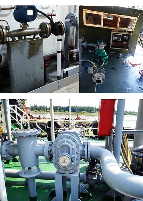
Fuel Flow Meter for Boat

At present, ships are in the process of refueling, especially for heavy fuel oil. The traditional method of measuring tank capacity is used to calculate the quantity of fuel oil. This method is very cumbersome and the accuracy is not high. And if the fuel flow meter is used, the above shortcomings can be well overcome.

There are many kinds of flowmeters on the market now, which makes it difficult for designers to choose their models. Different types of flowmeters have different characteristics. When choosing a suitable flowmeter according to the characteristics of the ship’s fuel oil, good test results can be achieved.

Instruments that measure the flow or total volume in pipe flow or open channel flow are collectively referred to as flow meters. There are many types of flow measurement methods and meters. The measuring principle, structural characteristics, scope of application and method of use are different.

Up to now, there are more than 60 types of flow meters available for industrial use. Because so far, there is no flow meter that can be used for any fluid, any range, any flow state, and any use condition.

There are many ways to classify flow meters. According to different classification principles, the classification methods are also different. Classified by principle, flow meters can be divided into three types: volumetric, velocity and differential pressure.

One of the more popular classification methods is from the measurement method and structure classification. It can be divided into: differential pressure flowmeter, positive displacement flowmeter, float flowmeter, impeller flowmeter, electromagnetic flowmeter, fluid oscillating flowmeter, ultrasonic flowmeter, mass flowmeter, plug-in flowmeter, open channel flowmeter There are 11 categories with other flow meters.

Read more about:

Precautions for flowmeter selection

  1. The performance of the flow meter

The performance of the flowmeter is embodied in the flow range, linearity, repeatability and accuracy.

The flow rate range is the range defined by the minimum flow rate and the maximum flow rate. When selecting the type, pay attention that the flowmeter cannot exceed this range under normal use conditions.

Linearity indicates the degree of consistency between the flow characteristic curve and the specified straight line in the entire flow range. According to this feature, the flowmeter output can be divided into linear and nonlinear square roots.

The non-linear error has a great influence on the pulse output type flowmeter with a large flow range. Repeatability refers to the consistency of the results obtained from multiple measurements of the same measured under the premise of the same conditions.

Generally, the higher the repeatability, the more concentrated the measurement value. Accuracy refers to the degree of agreement between the measured value and the actual value.

The lower the accuracy of the meter, the greater the error. The greater the deviation between the measured value and the actual value. When determining the accuracy, it should be selected according to the accuracy requirements of the actual measurement.

Extended Reading: Mechanical flow meter for diesel

  1. Working conditions

The working conditions that affect the flowmeter measurement mainly include temperature and electromagnetic interference.

The volumetric flowmeter uses a constant volume chamber to measure the flow rate. The material of the mechanical parts constituting the chamber is generally made of steel.

It becomes brittle when the temperature is low, and expands when the temperature is high. The pressure is limited at low temperatures.

For example, the twin-screw flowmeter in the fuel viscosity unit of the main engine on the actual ship. The rotor is often stuck during the light-to-heavy oil conversion. This is the reason.

In addition to the above and other conditions, it should be considered. Because of the particularity of the ship’s working environment, it is different from land. When choosing a flowmeter for a ship, it should also be combined with the actual working environment of the ship. Consider other factors that may affect the flowmeter. .

Ships are inevitably affected by many factors when sailing on the water, such as vibration, roll, impact, erosion, and sudden changes in climate. The operating environment is quite harsh. In order to ensure that the instrument can operate reliably and accurately in actual use, marine requirements must be considered when selecting models.

  1. Installation conditions

The installation conditions depend on the requirements of the site space and orientation. Specific instruments have special requirements. Therefore, the installation conditions should be given full attention.

For example, a positive displacement flow meter often requires the installation direction and flow direction of the sensor to be horizontal, vertical and horizontal respectively.
Positive displacement flow meters are sensitive to impurities and require filtration accuracy. Sometimes a filter device is needed. The float type flowmeter is more sensitive to the flow rate. Therefore, in order to eliminate the influence on the measurement. When limited by space, there are also flow regulators. Therefore, the space and orientation of the work site must be considered during installation.

Extended reading: Orifice Plate Flow Meter

Selection of Fuel Flow Meter for Boat

  1. Fuel performance

Fuel oil is a mixed liquid whose viscosity changes greatly with temperature, and there are many impurities in it.
Generally, when fuel oil is installed, it is realized through a closed delivery pipeline. The type of fuel generally installed on real ships is F120, and its density at 20°C is 981.6㎏/m3.

Combine these properties of fuel. Compared with the performance analysis of various flowmeters introduced above. Although volumetric flowmeters and turbine flowmeters have high accuracy, they have high requirements for fluid cleanliness. Electromagnetic flowmeters are only suitable for conductive liquids, so they are not applicable here. Coriolis mass flow meters can be used, but the cost is higher. Differential pressure flow meters are also optional. However, it is necessary to cooperate with a differential pressure transmitter for flow measurement and control.

  1. Working conditions of fuel flow meter

When the fuel flow meter is working, the temperature of the fuel passing through the flow meter is about 40°C. The agreed pump speed is 12m3/h, and the agreed maximum pump pressure is 0.4MPa. The amount of fuel added this time is 240t.

According to these few data, in the further flowmeter selection. Float flow meters should also be excluded. According to the characteristics of the float flowmeter, set up and measure the small flow of fluid. However, when the fuel is installed, the quantity is too large and it is not suitable for selection.

The vortex flowmeter works by using the principle of fluid oscillation. Avoid strong vibration when installing the sensor. However, according to the working conditions of the ship, the vibration and noise are very large. If a vortex flowmeter is selected, the measurement accuracy will be greatly affected in actual use.

It can be generally determined that both the differential pressure flowmeter and the ultrasonic flowmeter meet the requirements. Also, gear flow meters, mass flow meters, etc. These types of flow meters have a wide range of applications and are suitable for a variety of liquids.

Extended Reading: Guide and Selection for Diesel Fuel Flow Meters

Featured Fuel Flow Meter for Boat

The intelligent liquid turbine flowmeter is a new type of intelligent instrument that integrates the turbine flow sensor and display integration, which is developed by using advanced ultra-low power single-chip microcomputer technology. It has a compact structure, intuitive and clear reading, and high reliability. Not subject to external power supply. Obvious advantages such as lightning resistance and low cost.

Turbine Digital Flow Meter is widely used to measure the corrosion of stainless steel 1Cr18Ni9Ti, 2Cr13, corundum Al2O3, and cemented carbide in closed pipelines, and there is no fiber, particles and other impurities. Liquids with kinematic viscosity less than 5×10⁻⁶m2/s at working temperature, and liquids with kinematic viscosity greater than 5×10⁻⁶m2/s. The flowmeter can be used after real liquid calibration. If matched with a display instrument with special functions. It can also carry out quantitative control, over-quantity alarm, and so on. It is an ideal instrument for flow measurement and energy saving.

A Cylinder gear flow meter is a micro digital positive displacement flow meter. Can measure very small flow rates and quantify small volumes of liquid. High and low-temperature resistance (-196℃-200℃).

Cylinder Gear flow meter is a type of positive displacement flow transmitter. It is a high-precision transmitter for measuring volumetric flow. With the flow of the medium, the gears mesh and rotate. Under the action of fluid flow. Measure the number of revolutions of the gear to know the flow of liquid and liquid flowing through the instrument. It is especially suitable for the flow measurement of heavy oil, polyvinyl alcohol, grease, and other high-viscosity media. It can measure the viscosity of Fluid up to 10000Pa.s.

Oval gear flow meter is one of the typical positive displacement flow meters. Measure the flow of liquid filling the pipeline under a certain pressure.

Oval gear flow meter is a pointer display type positive displacement flowmeter. The word wheel accumulates counting, and can be equipped with a zero return device. Oval gear flowmeters are widely used in liquid flow control in various industrial fields. Applicable to various types of liquid measurement, such as crude oil, diesel, gasoline, etc. Choose different manufacturing materials, such as crude oil, diesel, gasoline, etc. can be measured.

PD Flow Meter is referred to as positive displacement flowmeter. Helical Gear-PD Flow Meter is also called, spiral double rotor flowmeter, LLT, LZ double rotor flowmeter or UF-Ⅱ spiral rotor flowmeter.

As a high-precision flow meter, PD Flow Meter has an accuracy of 0.2 level. It is especially suitable for the measurement of industrial liquids such as crude oil, refined oil and light hydrocarbons. It is a new generation volumetric flowmeter. Because it uses a pair of spiral rotors with special teeth, it is also called “Helical Gear Flowmeter”.

Marine Fuel Mass Flow Meter (MFM)

Mass flow meter directly measures the mass flow of the medium passing through the flow meter. It can also measure the density, temperature and viscosity of the medium

The Singapore Standards Committee issued the new Singapore Standard SS6481-Marine Fuel Mass Flow Meter (MFM) Usage Guidelines. To support the shipping industry’s formal implementation of the “Sulfur Restriction Order” from January 1, 2020 to improve the low-sulfur fuel system. And Guidelines for improving and regulating MFM fuel filling behavior.

Regarding Singapore’s new SS6481-Marine Fuel Mass Flow Meter (MFM) Code of Conduct. The Director of the Technical Committee for Bunkering (Chairman, Technical Committee for Bunkering) Seah Khen Hee pointed out——
“Metrology and system integrity are the dual foundations of SS648. It is the foundation of MFM system approval and fuel metering and handover procedures.”

Extended reading:

Singapore launches enhanced mass-flow metering standard

Sino-Inst, Manufacuturer for Fuel Flow Meter for Boat. For example: crude oil flowmeter, diesel flowmeter, gasoline flowmeter.

Sino-Inst’s Fuel Flow Meter for Boat, made in China, Having good Quality, With better price. Our flow measurement instruments are widely used in China, India, Pakistan, US, and other countries.

Request a Quote

Please enable JavaScript in your browser to submit the form

Guide for Digital Fuel Flow Meter

Digital Fuel Flow Meter is a flow meter dedicated to measuring fuel, diesel, gasoline, and petroleum. Digital Fuel Flow Meter generally has a digital display or signal output. Such as pulse or 4-20mA. Such as turbine flow meters, gear flow meters. It can be used to measure the pipeline flow of oil medium storage, transportation, trade, etc. Different pipelines and working conditions require flow meters with different principles or functions. Next, we will analyze in detail.

The digital diesel fuel flow meter comes with a large LCD display which is convenient for clear reading.
Another display method of Diesel fuel flow meter is the dual display of pointer and word wheel instantaneous cumulative count. Now it also supports electronic digital display, which makes the instantaneous and cumulative flow more intuitive. In the case of electronic digital display flowmeter mode, it can also realize the on-site online data remote transmission function to support different signal output modes. The pointer plus the word wheel display and the electronic digital display can be applied to more on-site working conditions and are widely used and recognized.

Extended reading: Fuel Flow Meter for Boat-Selection & Application

As a commonly used energy source in industrial production, diesel oil needs to be metered in many occasions. For pipeline transportation of oil tankers or diesel storage tanks, it is more suitable to select a flow meter with higher measurement accuracy to measure. Because not only to facilitate trade settlement. And it needs to be accurate. The measurement is accurate. Can be used for a long time.

The intelligent liquid turbine flowmeter is a new type of intelligent instrument that integrates the turbine flow sensor and display integration, which is developed by using advanced ultra-low power single-chip microcomputer technology. It has a compact structure, intuitive and clear reading, and high reliability. Not subject to external power supply. Obvious advantages such as lightning resistance and low cost.

Turbine Digital Flow Meter is widely used to measure the corrosion of stainless steel 1Cr18Ni9Ti, 2Cr13, corundum Al2O3, and cemented carbide in closed pipelines, and there is no fiber, particles and other impurities. Liquids with kinematic viscosity less than 5×10⁻⁶m2/s at working temperature, and liquids with kinematic viscosity greater than 5×10⁻⁶m2/s. The flowmeter can be used after real liquid calibration. If matched with a display instrument with special functions. It can also carry out quantitative control, over-quantity alarm, and so on. It is an ideal instrument for flow measurement and energy saving.

Most widely used types are mechanical and digital inline fuel meters. Differential flow sensors are available. Like: the turbine, positive displacement (oval gear), Coriolis, and differential pressure flow meters.

Sino-Inst offers a variety of fuel flow meters for most fuels. Including diesel, bio-diesel, kerosene, gasoline, oil, heating oil, grease, and certain chemicals. Sino-Instrument offers diesel fuel flow measurement solutions and free technical support. If you have any questions about diesel fuel flow measurement, please contact us.

Marine fuels mainly include light diesel, heavy diesel, fuel oil, and residual fuel oil.

To put it simply, if the tested marine fuel is a low-viscosity, clean fuel. Then you can choose a turbine flowmeter. The price is reasonable and the measurement is stable.

If the marine fuel being tested is heavy oil, high-viscosity fuel. Then it is recommended to choose an oval gear flowmeter.

If the measured marine fuel is a small flow rate. Then it is recommended to use a circular gear flowmeter for measurement.

If the tested marine fuel has impurities. It is recommended to install a filter before the flowmeter.

If you still do not know how to choose the right marine fuel flow meter. You can contact our sales engineer. We will provide you with a suitable marine fuel flow measurement program.

Read more about Large-diameter Oval Gear-Marine Fuel Flow Meter

Volumetric Flow Meter, as a mechanical flow meter, is also called Positive displacement flowmeter. It can measure the volume flow of high viscosity and corrosive fluids.

Volumetric Flow Meter is a mechanical instrument used to measure the volume flow of fluids. A volumetric flow meter is an instrument which can measure either directly or indirectly the volume of a substance which is passing through a specific location in a set period of time. The main advantage of these types of flow meters is that they can handle high viscosity and corrosiveness fluid.

Extended Reading: Magnetic Battery Operated Flow Meter

Electronic flow meters are industrial digital flow meters for fluid flow rate measurement. In more cases, people will default that Electronic flow meters are electromagnetic flowmeters.

Electronic flow meters types like Magnetic, Vortex, and Ultrasonic flow meters. Electronic flow meters are suitable for Industrial liquid, water, natural gas, petrol, fuel, air, and more fluid flow. Electronic flowmeters convert the monitored fluid flow into electronic signals. Including pulse signal, 4-20mA standard signal, etc.

Sino-Inst offers a variety of  Electronic flow meters for flow measurement. If you have any questions, please contact our sales engineers.

There is also a compact electronic turbine flowmeter.
It is widely used for small-caliber measurements of gasoline, diesel, water, methanol, alcohol, etc.

Extended Reading: Petroleum Flow Meter

GPI is a registered trademark of Great Plains Industries, Inc. of the United States. It has been producing turbine and oval gear flow meters for more than 30 years.

The headquarters of American GPI is located in Wichita, Kansas, USA. It is a global professional manufacturer of fluid transportation and measurement. Relying on its strong product development capabilities and complete turbine and elliptical gear flowmeter production lines and product testing lines. After more than 30 years of development, it has won the support and trust of more and more customers around the world.

In China, GPI products have been widely used in the chemical, oil, pharmaceutical, food and beverage, water treatment, and automotive equipment manufacturing industries.

GPI mainly produces two categories of products:
▲ GPI turbine flowmeter, oval gear flowmeter;
▲ GPI fluid delivery and storage system, including manual pumps, electric pumps, etc.

Extended Reading: Fuel Flow Meters for Diesel-Marine fuel-Industrial oil

Featured Digital Fuel Flow Meters

How to Choose the Right Digital Fuel Flow Meter?

There are many types of flow meters on the market, and the prices are different. There are so many brands at home and abroad, it is easy to get confused. So how should we choose the right flow meter?

To put it simply, we should start from the actual measurement conditions when choosing a flow meter. Combine installation requirements, monitoring requirements, and budget costs. In order to choose the most suitable Digital Fuel Flow Meter for you.

  1. Look at the condition of the fluid. Including fluid viscosity, corrosivity, etc. For example, for high-viscosity oils, gear flow meters are recommended. For low viscosity, turbine flowmeters can be used.
  2. Flow rate range. Minimum flow, maximum flow. Common flow.
  3. Pipeline diameter. The inner diameter, outer diameter, wall thickness, etc. of the pipe. Determine the caliber of the flowmeter according to the flow rate and the size of the industrial pipe. Generally, the flow meter that is consistent with the pipeline is selected. If the flow range does not meet, then operations such as necking can be considered.
  4. The temperature of the medium. For example, in the case of ultra-high temperature, the material and structure of the flow meter need to be changed.
  5. Pipeline pressure. Select the pressure level of the flanges connected on both sides according to the pressure level of the process pipeline. According to the different materials of the flowmeter in contact with the liquid, the pressure resistance is different, and the pressure resistance range of stainless steel and copper is larger. If the flow rate is relatively low, pressure loss needs to be considered. In this case, turbines and positive displacement flow meters are not suitable.
  6. Signal output. If signal output is not required, rotameter and mechanical water meter are generally sufficient. The output signal has analog quantity (4-20ma, 0-10 v) and pulse output, these flowmeters can have digital display.
  7. Accuracy requirements.
  8. Installation conditions. Some flow meters have strict requirements for straight pipe sections. Need to be considered in advance.
  9. Budget cost.
  10. Maintenance.

If you sort the above parameters, you don’t know which flowmeter you should choose. Then, you can contact Sino-Inst sales engineer. We will select the appropriate digital fuel flow meter according to your requirements.

Extended Reading: Guide and Selection for Diesel Fuel Flow Meters

Frequently
Asked
Questions

Different digital flow sensors include turbine, thermal mass, electromagnetic, ultrasonic, orifice plate, venturi. The different designs of the flowmeters have a variety of applications. With 4-20ma, RS485, or other output.

Then they all work differently. However, they can convert the flow signal into a digital display, or pulse, or 4-20mA signal.

Extended reading: Ultrasonic Flow Meters Types & Technical Guide

What is a fuel flow meter? The fuel flow meter is an instrument that can monitor fuel flow. Industrial Fuel is an important energy source. For example, diesel, marine fuel, gasoline, etc.

Extended Reading: Mechanical oil flow meter

A diesel Flowmeter is a kind of positive displacement Meter to measure the liquid flow or instantaneous flow of the Pipe tube. lt is a kind of accumulated meter. With Characteristics of high accuracy, small change by the fluid Viscosity, it is widely used to measure oil kind liquid, forbidden to measure corrosive.

Extended reading: More Inline Digital Diesel Fuel Flow Meters

Currently, the digital flow meters provided by Sino-Inst support flange installation, threaded installation, plug-in installation or external clamp installation. Different flow meters have different installation requirements.

Extended reading: Orifice Plate Flow Meter

Sino-Inst, Manufacuturer for Digital Fuel Flow Meters. For example: crude oil flowmeter, diesel flowmeter, gasoline flowmeter.

Sino-Inst’s Digital Fuel Flow Meters, made in China, Having good Quality, With better price. Our flow measurement instruments are widely used in China, India, Pakistan, US, and other countries.

Request a Quote

Please enable JavaScript in your browser to submit the form

Water Level Monitoring Sensor/System for Sewage-Wastewater

Water Level Monitoring Sensors can be used to detect changes in water level. The Water Level Monitoring Sensor and other control equipment work together to form the Water Level Monitoring System. The Water Level Monitoring Sensor/System is used to monitor the discharge of industrial wastewater and urban sewage. This is the development direction of smart cities. Let’s talk about Water Level Monitoring Sensor/System for Sewage-Wastewater in detail below.

Level monitoring

By installing a drop-in liquid level monitoring box at the head of the sewage well. Real-time monitoring of liquid level data of sewage wells. The monitoring data is uploaded to the platform through wireless communication. The cloud platform recognizes anomalies based on data statistical algorithms.

When the liquid level exceeds the set alarm threshold, the system will send an over-limit alarm. Notify relevant personnel to start the pump to drain water. When the level detector has equipment failure. Record the fault alarm. Notify relevant personnel to inspect the equipment.

Extended reading: Float Level Sensors – Single and Multipoint

Surface Water Level Monitoring is suitable for the water department to monitor the surface water level. At the same time, it supports remote image monitoring. Provide accurate and timely on-site information to ensure proper water storage and safe flood season.
It is helpful for the Water Affairs Bureau to grasp the current situation of water resources in the region, the use of water resources, strengthen the recovery of water resources fees, and achieve the purpose of correct evaluation, reasonable dispatch, and effective control of water resources.

  1. Remote monitoring function. It can remotely monitor real-time data such as water level, rainfall, field equipment operating status, equipment voltage and so on.
  2. Remote control function. The opening/closing of the reservoir valve can be remotely controlled in the center according to the height of the on-site water level to maintain the normal water level.
  3. Image monitoring function. An external camera can be connected. Live photos can be taken. The photos can be uploaded to the monitoring center. The staff on duty can understand the situation on the spot without leaving home. Support regular and manual photos.
  4. Automatic alarm function. It will automatically alarm if the water level exceeds the limit, the rainfall exceeds the limit, the equipment fails, and the door is opened abnormally.
  5. Automatic statistics function. According to historical data, automatic statistics into daily reports, monthly reports, annual reports, etc.. Generate analysis charts according to customer needs.
  6. Data storage function. The monitoring center and the field terminal can store historical data bidirectionally. It can store not less than 10 years of historical data.

Scope of application:

  1. River water level monitoring. Real-time monitoring of the water level of the river provides a basis for decision-making.
  2. Lake water level monitoring. The required information can be extracted by uploading real-time water level conditions.
  3. Water level monitoring of the reservoir. Real-time monitoring of the water level in the reservoir is convenient for timely water replenishment and does not affect production and life.
  4. The upstream and downstream water level monitoring of the reservoir. The water level changes of the upper and lower water levels can be reflected through the water level gauges of various manufacturers.
  5. Rainfall monitoring in the reservoir area. Rain gauge measurement is used as the basis for rainfall and rainfall intensity in the reservoir area.
  6. On-site picture monitoring of the reservoir. Industrial cameras upload on-site pictures of the reservoir area.
  7. Monitoring of the infiltration line of the dam of the reservoir. Observe the position of the infiltration line of the dam body by embedding a piezometer.
  8. Monitoring the seepage pressure of the dam foundation of the reservoir. The seepage pressure distribution of the dam foundation is reflected by the embedded piezometer.
  9. Reservoir dam displacement monitoring. Accurately understand the horizontal and vertical deformation of the dam surface.

Extended reading: Radar Water Level Sensor Applied To River/Reservoir Monitoring

The river water level monitoring system is suitable for the water management department to remotely monitor the water level, rainfall, and other real-time data of the river basin. At the same time, it supports remote image monitoring. It provides accurate and timely on-site information to ensure proper water storage and safety in the river basin.

The river water level monitoring system achieves real-time monitoring of water and rain conditions and realizes the information management of the river. It has played a major role in protecting people’s lives and property safety.

System Overview

The river water level monitoring system is an important method for real-time control of river water regime changes, scientific early warning of flood disasters, improvement of flood control command capabilities, and reduction of rain and flood disaster losses.

System functions

  • Real-time monitoring of river water level, can expand rainfall, water quality, flow rate monitoring.
  • Support remote camera or video real-time monitoring (depending on the communication method).
  • When the water level exceeds the limit, the sensor fails, and the battery voltage of the monitoring terminal is low, the alarm will be immediately alarmed.
  • Automatically generate water level process curve and data statistics report.
  • It can be linked with the drainage pump station to automatically control the start and stop of the drainage pump group according to the water level of the river.
  • Supports docking with other comprehensive monitoring application platforms through OPC, database and other forms.

System Features

  • Strong compatibility: Compatible with various types of water level gauges such as ultrasonic, radar, float, laser, bubble, and drop-in type.
  • Flexible form of power supply: According to site conditions, it can be flexibly selected to supply power to the equipment by means of city electricity, solar energy, batteries, etc.
  • Various communication methods: support GPRS, CDMA, NB-IOT, short message, Beidou satellite, 3G/4G, WIFI, ADSL/optical fiber and other communication methods.

Extended Reading: GWR Level Sensor for High Temperature & High Pressure

The water level control switch is a feedback liquid level position signal. It informs the center console of the duty room whether the water level has reached the specified water level. It can also control the startup or shutdown of related equipment (such as water pumps). The signal voltage is often a safety voltage of 12V or 24V.

Water Level Control Sensor Switch is widely used in industrial boilers, civil construction pools, water towers, water tanks. As well as open or closed storage tanks in petrochemical, paper, food, sewage treatment, and other industries. Level measurement of various liquids in underground tanks. The tested medium can be divided into various conductive and non-conductive liquids such as water, oil, acid, alkali, industrial sewage, and so on. It forms a set of advanced liquid level display and control equipment with the electric valve, which automatically opens and closes the electric valve.

Extended reading: RF Admittance Level Sensor

Tank level sensor is a common sensor for measuring liquid level position. It converts the height of the position into an electrical signal for output. The liquid level sensor is a modular circuit. It has the advantages of acid resistance, moisture resistance, shock resistance, and corrosion resistance. The circuit contains a constant current feedback circuit and an internal protection circuit. The maximum output current can be made to not exceed 28mA. Therefore, the power supply can be reliably protected and the secondary meter is not damaged. In general, it is used in electrical appliances and equipment that require water level control.

Read more Tank Level Gauges & Indicators.

We can divide Water Level Sensors into two categories by measuring whether they are in contact with the water level.

One type is contact type. Including single flange static pressure/double flange differential pressure level transmitter, float type level transmitter, magnetic level transmitter, input type level transmitter, electric internal float level transmitter Sensors, electric float level transmitters, capacitive level transmitters, magnetostrictive level transmitters, service level transmitters, etc.

The second category is non-contact. Divided into the ultrasonic level transmitter, radar level transmitter, and so on.

Extended Reading: Chilled Water Flow Meter

Ultrasonic liquid level Sensor adopts an ultrasonic pulse-echo method to realize liquid level measurement. Specifically, the transducer (probe) of the ultrasonic liquid level Sensor sends out high-frequency ultrasonic pulses. When it encounters the surface of the liquid level to be measured, the sound wave is reflected back. Part of the reflected echo is received by the transducer (probe) and converted into an electrical signal. The user can know the water level almost in real-time based on the reflected signal.

When choosing a water level measuring instrument, it is recommended to measure the ultrasonic liquid level Sensor here. It adopts microprocessor program control technology and intelligent signal processing technology. The measurement is efficient and accurate.

Read more about: Common River Water Level Measurement Methods

The protection level of the whole machine is as high as IP66/IP67, which can effectively prevent dust from inhaling, and can be immersed in water for a short time. At the same time, the probe is made of high explosion-proof grade (Ex d IIC T6 Gb) and PVDF material. It is very suitable for applications in harsh and noisy outdoor environments with corrosive liquids, harsh working conditions, and strong interference.

In addition, the ultrasonic liquid level Sensor has a variety of ranges to choose from. The longest can be measured at 15 meters. Very suitable for long-distance detection and tank level detection.

In addition to the use of ultrasonic level Sensors for water level monitoring. Users can also use radar, depth water level sensors, and other technologies to monitor the water level. Instead, use an ultrasonic liquid level. It is a liquid-level measuring instrument with a low maintenance cost and wide application range at present. Users can accurately obtain all required data. And with high-cost performance, it is favored by the majority of users.

Extended reading: Hydrostatic Level Measurement

Featured Water Level Monitoring Sensors

Wastewater/sewage pipe network flow and liquid level online monitoring solution

The online monitoring system for the flow and liquid level of the drainage/sewage pipe network is an important part of the intelligent drainage construction in Anhui. Through this system, the management department can globally grasp the operating status of the drainage pipe network, effectively identify the silting pipe section, and discover the abnormality of the manhole cover in time. In order to quickly respond to flood prevention and protect residents’ travel safety.

On-site monitoring equipment composition:

  • Well monitoring RTU: battery-powered, IP68 waterproof RTU
  • Water level detection equipment: drop-in level gauge (ultrasonic level gauge and other level gauges can also be used)
  • Manhole cover status detection equipment: travel switch (limit switch)

System implementation instructions

1) The limit switch is installed under the manhole cover. When the manhole cover was closed, it just touched the contact of the travel switch. When the manhole cover is moved, the contact state of the limit switch changes. Such as from “open” to “closed”. And output this state change signal to the manhole monitoring RTU through the cable.

2) The probe of the throw-in water level gauge is installed at the bottom of the manhole and fixed firmly. Real-time detection of water level data in the manhole. And output the data to the manhole monitoring RTU through the cable.

3) Under normal circumstances, the well monitoring RTU regularly (time interval can be set) transmits the status and water level data of the well cover to the monitoring center through the GPRS/CDMA/4G/NB-IoT network. When the state of the manhole cover changes or the water level data exceeds the preset alarm value. The well-monitoring RTU reports alarm information to the monitoring center in real-time.

4) The center’s drainage pipe network monitoring system software dynamically displays the water level data and manhole cover status of each manhole. It provides query, statistics, and analysis functions, and prompts alarm information in various forms such as pop-up windows, prompt sounds, and short messages.

System functions

  • Monitor the water level of the wells at the important nodes of the pipeline network, and detect the siltation and blockage of the pipeline network in time.
  • Monitor the status of the manhole cover, and immediately alarm when the manhole cover is lost or displaced.
  • Provide timely warning information on the operation of the pipeline network to provide a decision-making basis for emergency flood prevention work.
  • Diagnose the bottleneck pipe section in the drainage pipe network, and provide a basis for the pipe network transformation.
  • Provide analytical data for evaluating the drainage capacity of low-lying and flood-prone areas.
  • Trace the historical status of the pipeline network operation to assist in accident analysis.

Extended reading: Radar Level Sensor Working Principle

Water Level Sensor Working Principle

The function of the water level sensor is to detect the water level. The water level sensor is widely used in electrical appliances and industrial equipment that require water level control. The water level sensor can realize the function of water shortage protection.

Principle of water level sensor:
The water level sensor has a sensor. Transform the sensed water level signal into a current signal.

There are many types of water level sensors, so their specific measurement principles are different.
If you need to learn more. You can refer to:
Differential pressure type liquid level measuring instrument;
Float level measuring instrument;
Electric liquid level measuring instrument;
Ultrasonic liquid level measuring instrument;
Radar liquid level measuring instruments, etc.

Extended reading: Capacitive water level sensor

More level measurement solutions

List of Radar Level Sensors

Non-contact radar level sensor Radar level sensors are used for continuous non-contact level measurement of liquids or solids. And…

Capacitive Fuel Level Sensor

The capacitive fuel level sensor refers to a capacitive liquid level transmitter used to measure the oil level. According…

Frequently
Asked
Questions

If it is just an ordinary tank or well water level measurement. Then our first choice is the hydrostatic pressure submerged liquid level sensor. Also called hydrostatic level sensors.

Because of its lowest cost. Installation, use and maintenance are very simple.

Extended reading: Float Switch Water Level Controller

Accurately measure the water level. In turn, the water level can be better controlled within the allowable range. It is of great significance to ensure safety and improve economic efficiency.
for example:
Many types of equipment in thermal power plants need to maintain a normal water level in order to operate safely and economically.
For example, boiler drum water level, deaerator water level, steam turbine condenser water level, high and low-pressure heater water level, etc.

Extended Reading: FMCW Radar for High Temperature Level Sensor

Extended Reading: Wireless Water Meter

Sino-Inst offers over 50 Water Level Monitoring sensors/Systems for Sewage-Wastewater. About 50% of these are Radar level meters, 40% is magnetic level sensor.

A wide variety of Tank Level Gauges & Indicators for Water Level Monitoring sensors/Systems for Sewage-Wastewater options are available to you, such as free samples, paid samples.

Sino-Inst is a globally recognized supplier and manufacturer of Water Level Monitoring Sensor/System for Sewage-Wastewater instrumentation, located in China.

Request a Quote

Please enable JavaScript in your browser to submit the form

The Myth of Ceramic Pressure Sensor

What is a ceramic pressure sensor?

Ceramic pressure sensors are sensor diaphragms made of ceramic alumina (Al2O3). Ceramic is a material with high elasticity, corrosion resistance, wear resistance, impact, and vibration resistance. Ceramic has good thermal stability characteristics. High-temperature sintering process for the thick film. The working temperature range of the ceramic pressure sensor is as high as -40~125℃. The high elasticity and creep resistance of ceramics. The ceramic pressure sensor has good long-term stability. Besides, the corrosion resistance of ceramics. It has advantages in the fields of refrigeration, chemical industry, and environmental protection.

The Basic Structure of Ceramic Pressure Sensor

The ceramic pressure sensor is mainly composed of a ceramic ring, a ceramic diaphragm and a ceramic cover plate.
The ceramic diaphragm acts as a sensitive elastic body. It is made of 95% AL2O3 porcelain. It is required to be flat, uniform and dense. Its thickness and effective radius depend on the design range.

The porcelain ring is shaped by high-temperature firing using a hot die-casting process. High-temperature glass slurry is used between the ceramic diaphragm and the ceramic ring. It is fired together by thick film printing and thermal firing technology. It forms a cup-shaped elastic body with a fixed peripheral edge. That is, a non-creep rigid structure should be formed in the fixed support part of the ceramic periphery.

On the upper surface of the ceramic diaphragm, which is the bottom of the porcelain cup. The circuit of the sensor is made with thick film technology. The circular groove at the lower part of the ceramic cover creates a certain gap between the cover and the diaphragm. The limit can prevent the diaphragm from rupturing due to excessive bending when it is overloaded. Form the anti-overload protection of the sensor.

Extended reading: Common Pressure Sensor Applications

Featured SI-338 Ceramic Pressure Sensor

SI-338 Ceramic pressure sensor uses ceramic or diffused silicon core. All stainless steel package, small and beautiful appearance. Suitable for occasions with limited installation space. Wide range temperature compensation, high accuracy, small size, no adjustment, wide range coverage. Support OEM processing. Ceramic pressure transmitter is used in compressor, air conditioning and other pressure measurement.

Extended reading: What Is Flush Diaphragm Pressure Sensor?

Features of Ceramic Pressure Sensor

Ceramic is a recognized material with high elasticity, corrosion resistance, wear resistance, impact and vibration resistance. The thermal stability of ceramics and its thick film resistors can make its operating temperature range as high as -40 to 135°C. It also has high accuracy and high stability for measurement. Electrical insulation degree>2kV. Strong output signal. Good long-term stability.

Ceramic sensors with high characteristics and low prices will be the development direction of pressure sensors. In Europe and the United States, there is a trend to completely replace other types of sensors. In China, more and more users use ceramic sensors to replace diffused silicon pressure sensors.

  • Ceramic sensitive diaphragm with high overload capacity;
  • Zero point and full scale laser calibration;
  • Excellent anti-corrosion and anti-wear performance;
  • Anti-shock and anti-vibration;
  • High precision and high stability;
  • Wide operating temperature range;
  • Small size, easy to package;
  • Environmental friendly;

Extended reading: What is a pressure sensor?

Ceramic Pressure Sensor Working Principle

The corrosion-resistant ceramic pressure sensor has no liquid transmission. The pressure directly acts on the front surface of the ceramic diaphragm, causing the diaphragm to produce a small deformation.

The thick film resistor is printed on the back of the ceramic diaphragm. Connected to form a Wheatstone bridge (closed bridge).

Due to the piezoresistive effect of the varistor, the bridge generates a highly linear voltage signal proportional to the pressure and proportional to the excitation voltage. The standard signal is calibrated to 2.0 / 3.0 / 3.3 mV/V according to the pressure range. Etc. Compatible with strain gauge sensors.

Calibration by laser. The sensor has high temperature stability and time stability. The sensor comes with a temperature compensation of 0~70℃. It can be in direct contact with most media.

Extended Reading: Up to 800°C High Temperature Pressure Sensor

Ceramic Pressure Sensor Types

The base material of ceramic pressure sensor is Al2O3 ceramic. According to the principle of realization, it can be divided into capacitive pressure sensor and piezoresistive pressure sensor.

The ceramic substrate and diaphragm are plated with metal and used as electrodes. The two ceramic parts are connected together by a glass seal. Maintain a controllable gap. So that the two metal electrodes form a capacitor.

If pressure is applied. Then the gap between the substrate and the diaphragm will be changed. Thereby changing the capacitance of the sensing element. The pressure-related signal output is formed by the subsequent processing circuit.

Because the edge of the ceramic diaphragm is fixed on the ceramic base. Peripheral support. When the force is applied, the middle deformation becomes larger, and the edge becomes smaller. The capacitance produces nonlinearity and reduces sensitivity.

In order to reduce temperature effects and edge effects. In the design, a circular single electrode is set on the ceramic diaphragm as the common electrode. Two electrodes are arranged on the ceramic cover plate to equalize the area. It forms a coaxial ring-shaped dual-capacitance sensor.

Extended Reading: MEMS Pressure Sensors

The center is the measurement capacitance Cp. The edge ring is the reference capacitor Cr. The outside of Cr is the fixed side. The subsequent signal conditioning circuit deals with the voltage difference between the two capacitors. The change of Cp and Cr is converted into DC voltage output by using square wave excitation signal. The magnitude of the applied pressure is measured by the difference signal of the two output voltages.

The dual-capacitor structure greatly reduces the nonlinear error of the sensor system. At the same time, when the ambient temperature changes, the two capacitors experience the same temperature change. The temperature effect of temperature on them is consistent. This offsets the measurement error caused by temperature changes. Realize the function of temperature self-compensation.

Extended reading: Featured Diaphragm Seal Pressure Transmitters

The piezoresistive pressure sensor is mainly composed of a ceramic ring, a ceramic diaphragm and a ceramic cover plate.

The ceramic diaphragm acts as a sensitive elastic body. On it, a thick film process technology is used to form a Wheatstone bridge as the sensor circuit. Due to the piezoresistive (deformation) effect of the resistor, a voltage signal is generated.

The thick film resistor is printed on the back of the ceramic diaphragm. Connected as a Wheatstone bridge (closed bridge).

When the pressure is zero. The bridge is in a balanced state, and the output voltage is zero.

When pressure is applied to the bridge. The deformation of the diaphragm causes the resistance of the four resistors of the bridge to change. The bridge is in an unbalanced state. Generate a highly linear voltage signal proportional to the pressure and proportional to the excitation voltage.

Due to the piezoresistive (deformation) effect of the resistor, a voltage signal is generated.

The standard signal is calibrated to 2.0 / 3.0 / 3.3 mV/V etc. according to the pressure range. Compatible with strain gauge sensors.

Calibration by laser. The sensor has high temperature stability and time stability. The sensor comes with a temperature compensation of 0~70℃. And can be in direct contact with most media.

Extended reading: Silicon Pressure Sensor

Frequently
Asked
Questions

There are many types of pressure sensors. Such as resistance strain gauge pressure sensors, semiconductor strain gauge pressure sensors, piezoresistive pressure sensors, inductive pressure sensors, capacitive pressure sensors, resonant pressure sensors, etc.

Extended reading: wireless pressure transmitter working principle

Currently, the most widely used pressure sensors include:

  • Diffused silicon piezoresistive pressure sensor,
  • Ceramic piezoresistive pressure sensor,
  • Sputtering thin film pressure sensor,
  • Capacitive pressure sensor,
  • Sapphire pressure sensor with high temperature resistance.
  • But the most widely used is the piezoresistive pressure sensor, which has a very low price, high accuracy and good linearity.

Extended Reading: Electronic Pressure Switch for Air Compressor

The piezoresistive pressure sensor is constructed using the piezoresistive effect of single crystal silicon. A single crystal silicon wafer is used as an elastic element, and an integrated circuit process is used on the single crystal silicon membrane. A group of equivalent resistors are diffused in a specific direction of the single crystal silicon, and the resistors are connected into a bridge circuit. The single crystal silicon wafer is placed on Sensor cavity. When the pressure changes, the single crystal silicon produces strain, so that the strain resistance directly diffused thereon changes proportional to the measured pressure. Then the bridge circuit obtains the corresponding voltage output signal.

Extended reading: How do you calibrate a smart pressure transmitter?

Differential pressure sensor, as the name suggests, is a kind of sensor. But it is used to transmit pressure difference. So it is called differential pressure sensor.

Generally speaking, its function is mainly to measure the difference between two different pressures. And it is displayed by the sensor. The differential pressure sensor is often used to measure the pressure of the two end points before and after a certain part of a device Difference.

Extended reading: Miniature Pressure Switch

Extended Reading: Selection of pressure transmitter

Ceramic Pressure Sensor Cost

Ceramic Pressure Sensor has low cost. The price of the ceramic pressure transmitter that people often choose is basically between USD15~35. Save a lot of costs for customers.

Extended reading: extrusion melt pressure transducer

Sino-Inst offers Ceramic Pressure Sensors. A wide variety of Ceramic Pressure Sensors options are available to you. Such as free samples, paid samples. 

Sino-Inst is a globally recognized manufacturer of Ceramic Pressure Sensors, located in China. Sino-Inst sells through a mature distribution network that reaches all 30 countries worldwide. 

Pressure sensors products are most popular in Europe, Southeast Asia, and Mid East. You can ensure product safety by selecting from certified suppliers. With ISO9001, ISO14001 certification.

Request a Quote

Please enable JavaScript in your browser to submit the form