Magnetic Level Gauge/Indicator

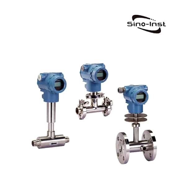
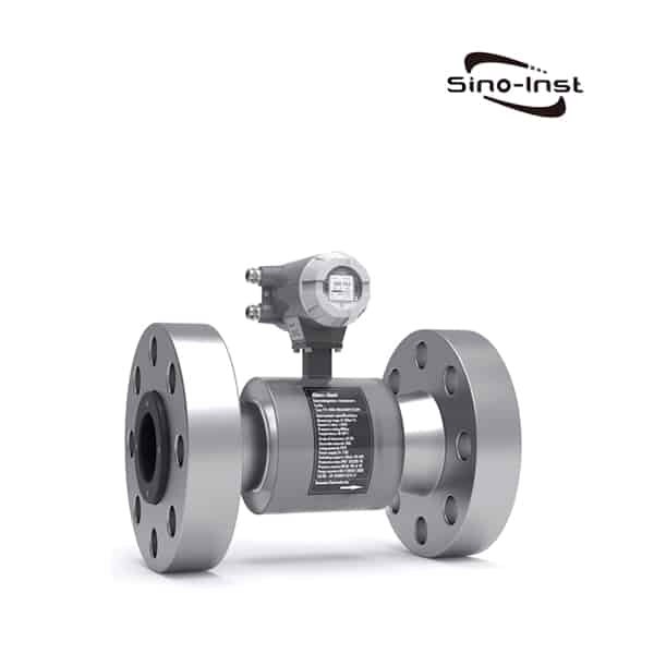
What is a magnetic type level gauge?

A magnetic Level Gauge is also called a magnetic level indicator. Magnetic Level Gauge is developed based on the principle of buoyancy and magnetic effect. The magnetic float in the measuring cylinder drives the two-color turning column on the external display of the measuring cylinder to flip with the increase (decrease) of the liquid level to be measured. As the position of the float changes, the indicator moves up and down the same amount. Supports top-mounted and side-mounted. It can be used for liquid level detection in high temperature, low temperature, high pressure, strong corrosion, highly toxic and dangerous environments.

Magnetic Level Gauge/Indicator

The parts and components of Magnetic Level Gauge are made of 304, 321, 316L, 1Cr18Ni9Ti, 00Cr17Ni14Mo2, 0Cr18Ni9, 304 or 0Cr18Ni9 lined with PTFE (polytetrafluoroethylene), PVC, PP, and other materials. And imported high-quality electronic components. The product has high reliability, good stability, long-lasting durability, and strong corrosion resistance.

Its characteristics are very significant:

  • Simple structure, Sturdy and reliable, durable, almost no maintenance workload, can be installed and used outdoors for a long time;
  • The measured medium is completely isolated from the display part of the level gauge, the level sensor, and the magnetic switch;
  • Wide working pressure range, withstand pressure from vacuum to 42MPa. The lowest density can reach 0.45g/cm3;
  • Wide operating temperature range, suitable for -190~+425℃;
  • Not affected by the physical and chemical state of the measured medium. Such as the medium’s conductivity, dielectric constant, foam, pressure, temperature, evaporation, boiling, bubbles, etc. It is widely used in various strong and weak corrosive, flammable and explosive. Toxicity, strong radioactivity, agitated, dirty liquid level, and interface measurement;
  • Optional single-pole single-throw (SPST), single-pole double-throw (SPDT) passive bistable magnetic switches. Realize high and low liquid levels, interface control, or alarm. The number of magnetic switches is not limited.
  • Optional reed pipe liquid level sensor, magnetostrictive liquid level sensor, capacitive two-wire liquid level sensor. Output 4~20mADC (or with HART protocol) signal. Realize remote centralized measurement and control.
  • The two-wire liquid level sensor can be equipped with LED digital display, which is convenient for night observation.

Installation form content

Side-mounted

Top-mounted

Installation spacing

Stainless steel

500~5000(mm)

500-2500(mm)

(Survey range)

ABS、PP-R

500~4000(mm)

Work pressure

0.6,1.6,2.5,4.0MPa

0.6,1.6,2.5MPa

Media density

0。6g/c

0.76g/c

Fallan Connection

Stainless steel

Farange 20-40 (DN20 PN1.0-4.0)
(GB9119-88)

Farange 200-25 (DN200 PN1.6)
(GB9119-88)

ABS

Farange 20-10 (DN20 PN1.0)
(GB9119-88)

Farange 200-6 (DN200 PN0.6)
(GB9119-88)

Main material

ICr18Ni9Ti, ABS, PP-R (working pressure of 0.6MPa)

Medium temperature

-40~100℃(ABS、PP-R:-40~80℃)

Environmental temperature

-40~+70℃

Schematic error

±100mm

Medium viscosity

≤1st(10-4 /s)

Upper and lower limits
Switch output

1, control sensitivity: 10mm
2, output connector capacity: AC220V 2A
3, connection life: 5 × 104 times
4, explosion-proof characteristics: iaIICT4 essential safety type

Electric teletransmission and continuous display

1, accuracy:±1.5%
2, Output load: 750 Ω
3, output signal: 4~20mA output, 24V DC second-line system
4, explosion-proof characteristics: iaIICT4 essential safety type

In order to meet the needs of different occasions, environments, and functions, Magnetic Level Gauge can add the following options:

  • Optional single-pole single-throw (SPST), single-pole double-throw (SPDT) passive bistable magnetic switches to achieve high and low liquid level, interface control or alarm. The number of magnetic switches is not limited.
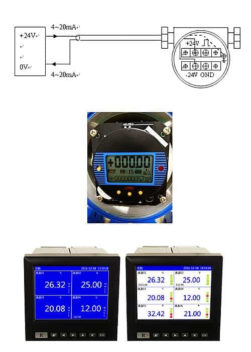
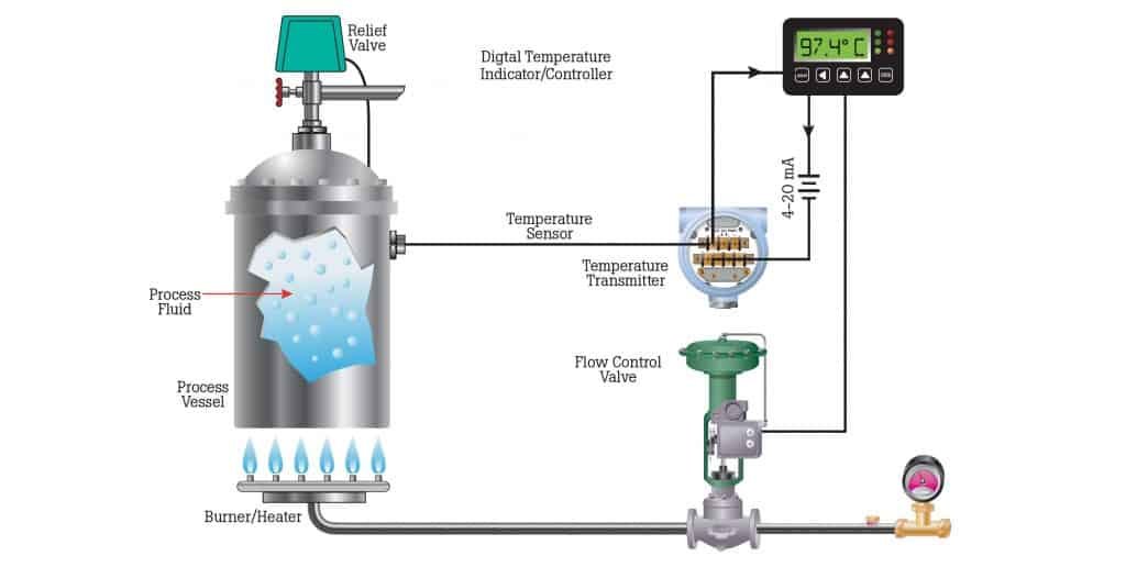
  • Optional two-wire magnetic liquid level sensor, output 4~20mADC signal, realize remote measurement and control,
  • Optional two-wire magnetostrictive or capacitive liquid level sensor, output 4 ~ 20mADC, to achieve high-precision, continuous measurement and control. Selection of the technological interface form of the level gauge.
  • The top and bottom structure of the level gauge are selected. Output 4~20mADC with HART protocol

Image source: https://instrumentationforum.com/t/magnetic-liquid-level-gauges-working-principle/5242

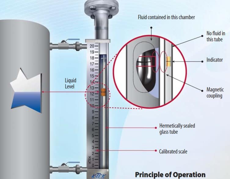
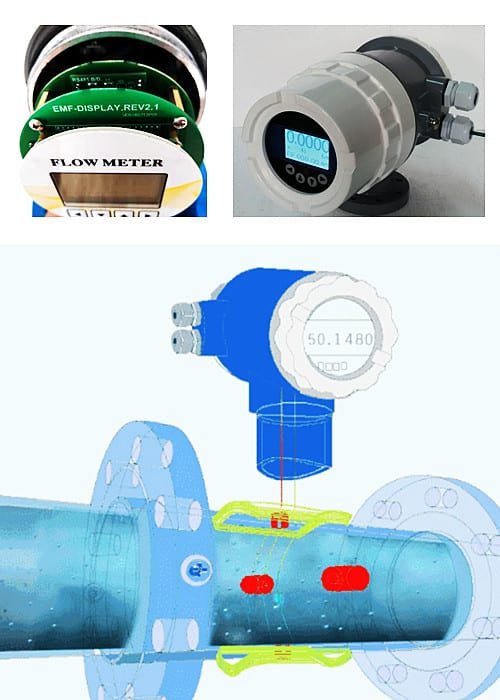
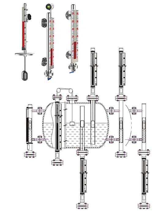
The Magnetic Level Gauge adopts the principle of the communicating device and is connected to the container through the gas-phase and liquid-phase connection flanges. According to the principle of buoyancy and magnetic coupling, the magnetic float in the measuring cylinder (that is, the communicating device) drives the two-color flipping column on the external display of the measuring cylinder to flip with the increase (decrease) of the liquid level to be measured.

When the liquid level rises, the magnetic float drives the turning column to rotate 180°, displaying red or green; when the liquid level drops, the magnetic float drives the turning column to rotate 180° in reverse, displaying white. The height of the red band (or green band) is the height of the measured liquid surface, which realizes the purpose of measuring and displaying the position of the measured liquid (interface) surface.

Each magnetic turning column is a two-color axial symmetric structure. The distance between the two magnetic turning columns is 10mm. White and red (or green) are used to indicate the gas phase and the liquid phase, and the red (or green) and white junctions It is the boundary between the liquid phase and the gas phase.

Magnetic Level Gauge can measure both the liquid level and the interface between two different density media.

Product standards: HG/T2742-1995, HG/T21584-95.
Flange executive standard: HG/T20592~20615—2009 (when the order is not specified)

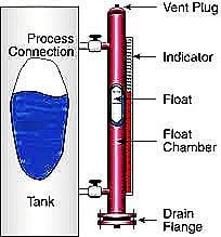
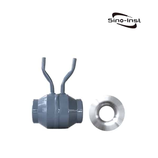
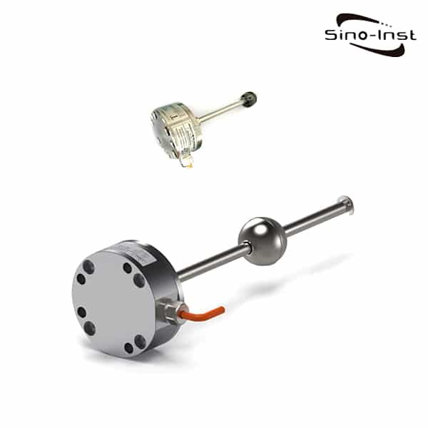
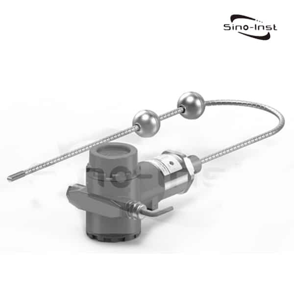
The working principle of the magnetic level gauge is to communicate with the container, so the liquid level in the measuring chamber will be the same as the liquid level in the container. The measuring chamber is equipped with a float, and there is a magnet in the float.

The float with magnets will float on the medium, and the magnets in the float will rotate the flaps of the indicating rail. The float in the measuring tube is standard, there is no pressure, no magnetism, or mechanical guidance.

This structure makes the risk of the float lower than that of the standard pressurized float. When necessary, pressurized floats can be produced.

With the below-mentioned process conditions, it is possible to select a float that will float on the medium.

  • Medium
  • Density
  • Working pressure
  • Operating Temperature

Magnetic Level Indicators can be directly used to observe the level of the medium in various containers. It is suitable for liquid level indication in petroleum, chemical, and other industrial fields. The liquid level gauge has a simple structure, intuitive and clear observation, no blockage, no leakage, convenient installation, and simple maintenance.

Extended reading: RF Admittance Level Sensor

Magnetic Level Gauge can be widely used in petroleum, chemical, oil field, medicine, food, wine, and other industries.

Various liquid storage tanks, storage tanks, liquid storage tanks, reaction tanks, fermentation tanks, liquid ammonia storage tanks, ammonia separators, boiler drums, deaerators, drain boxes, return tanks, high and low-pressure heaters, condensers, Evaporator.

Measurement and display of the liquid level of the medium compatible with 304, 321, 316L, OCr18Ni9, 304 or 0Cr18Ni9+PTFE, 00Cr17Ni14Mo21Cr18Ni9Ti, PVC, PP, and other materials in other pressure vessels, and the interface of two different media.

There are a variety of installation forms for you to choose from, to meet the requirements of different occasions and environments.

Magnetic Level Gauge can be reliably used for liquid level detection in high temperature, low temperature, high pressure, strong corrosion, highly toxic, and dangerous environments.

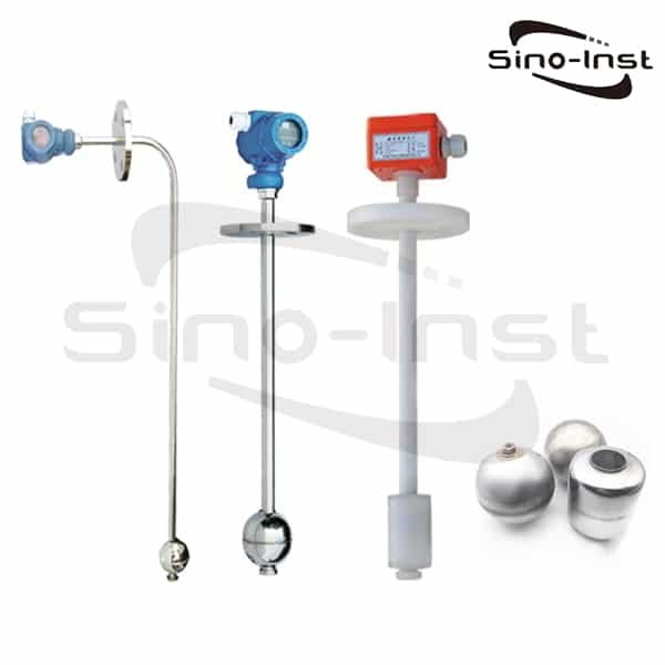
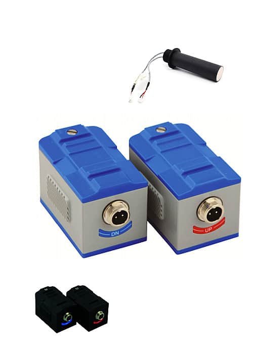
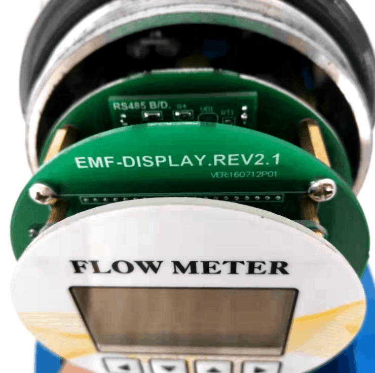
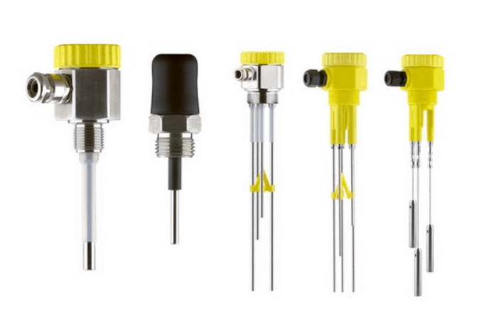
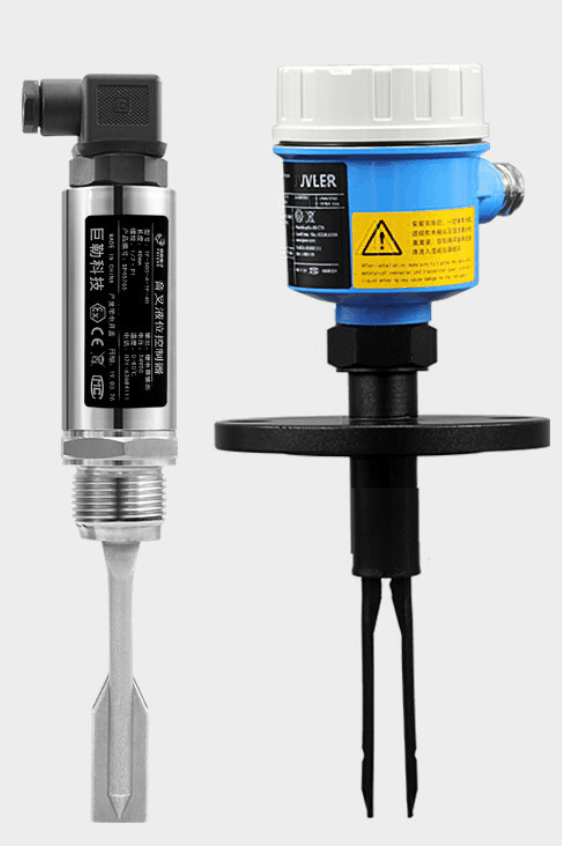
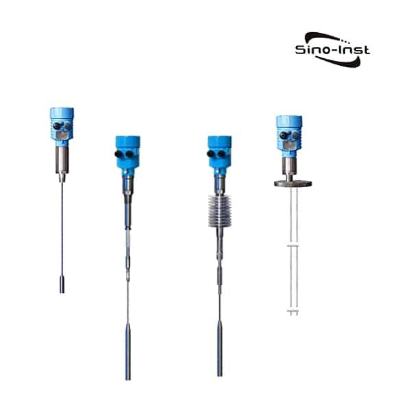
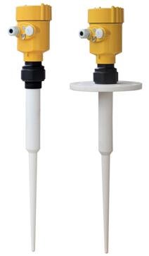
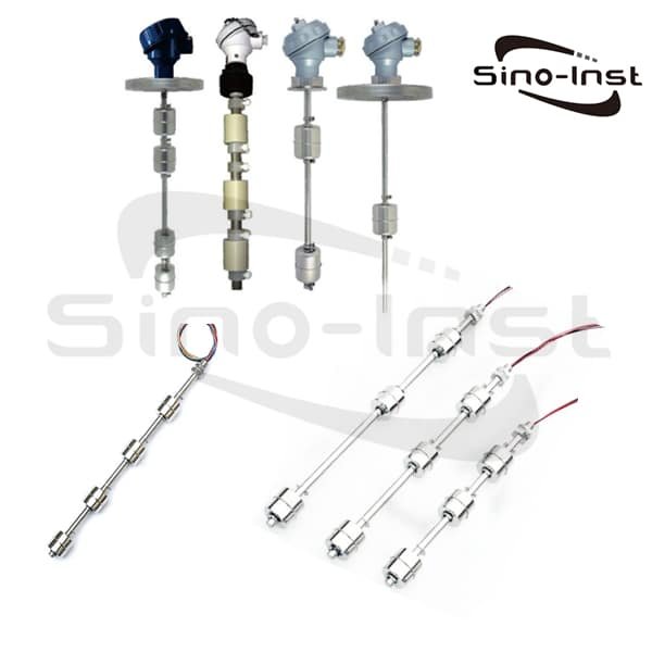
Magnetic Float Level Switches & Sensors with Magnetic Reed Switches for Continuous Level Measurement.

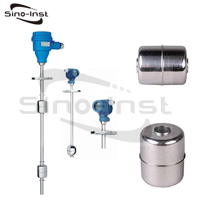
Magnetic Float Level Sensor works with Reed Switch, is a continuous level sensor. SI-U04 Magnetic Float Level Sensor-Reed operates on a direct, simple principle. As the magnetic float rises and falls as liquid levels change. The magnetic field generated from the inside of the float drives the sealed reed switch installed in the stem. The stem is made of non-magnetic metal or strong engineering plastic.

Magnetic Float Level Sensor gets the liquid level signal, transfers it into digital current signal and switching signal. Generally speaking, there are two structures of magnetic floats. Besides, the Magnetic Float Level Sensor supports multiple mounting methods. Such as top-mounted, side-mounted. So SI-U04 Magnetic Float Level Sensor can be applied to a variety of tank level measurements.

Extended reading: Amazing Solutions for Continuous Liquid Level Measurement

Still have questions?

If you cannot find an answer to your question in our FAQ, you can always contact us
and we will be with you shortly.

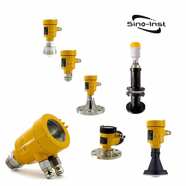
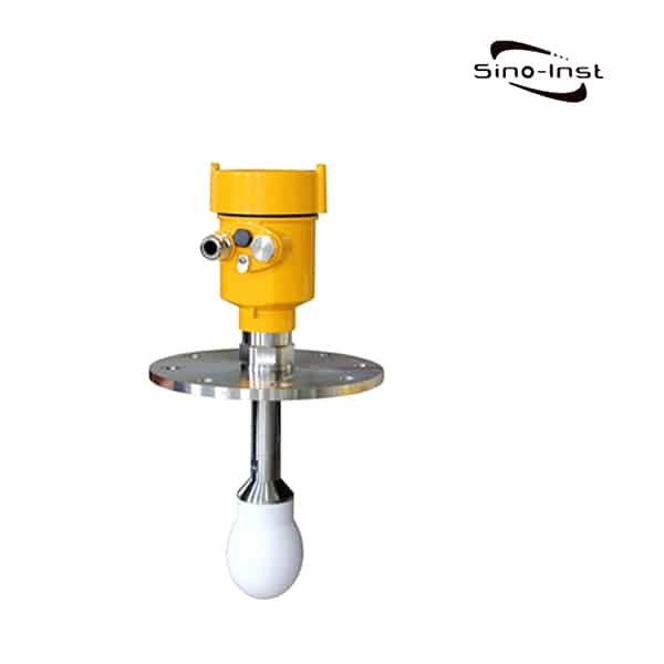
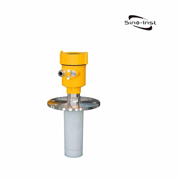
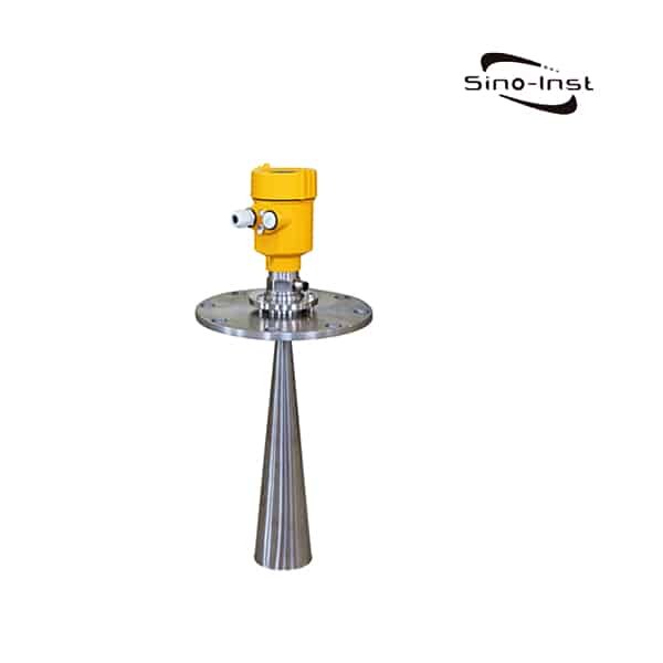
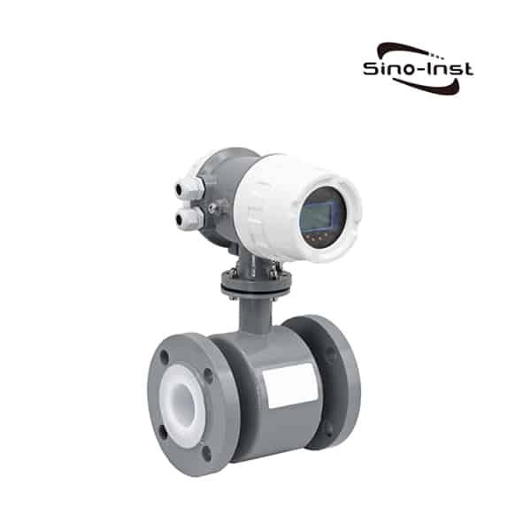
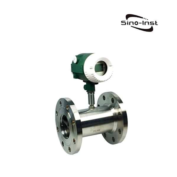
More Featured Level Gauges/Indicators

SI-U01 Float Level Sensor
SI-U02 Multi-Point Liquid Level Float Switch
Rigid Probe Magnetostrictive Level Transmitter
Integral flange Magnetostrictive level sensor
Digital Display Magnetostrictive liquid level sensor

Based on the product selection, we can determine the price of the level transmitter. Sino-Instrument is a manufacturer of level transmitters, so we offer the best price.
For example: The reference price of a differential pressure level transmitter is around USD 400.

Request a Quote

Please enable JavaScript in your browser to submit the form

Velocity Flow Meters

What is a velocity flow meter?

Velocity Flow Meter is a flow meter that obtains flow parameters by directly measuring the flow rate of the full pipe in the closed pipe section. The flow rate can be calculated by measuring the velocity of the flow by using a velocity flow meter. Velocity flow meters mainly include-electromagnetic, ultrasonic, turbine, vortex, precessing vortex, rotor, etc.

LEARN MORE

Flow Meter Types

There are many types of flow meters. Basically, there are the following types of flow meters

  • Volumetric type: waist wheel, oval gear, piston, etc.
  • Velocity type: electromagnetic, ultrasonic, turbine, vortex street, precession vortex, rotor, etc.
  • Differential pressure type: orifice, bar type such as annubar, V cone, wedge type, elbow, nozzle, target type, etc.
  • Variable area: rotors, open channels, etc.
  • Quality: Coriolis, thermal type, etc.

Why are there so many types of flow meters? This starts with the working conditions of the factory. The three elements of working conditions, medium, temperature, pressure, and conditions are ever-changing. Create thousands of types of working conditions. It requires different principles and different types of flow meters.

Extended reading: Integral DP Flow Meter|Gas, liquid, steam|Compact structure

Velocity Flow Meter Types

A magnetic Flow Meter is a flow meter that measures the flow of conductive fluids. Abbreviated as EMF, also called Electromagnetic flowmeters. It is a kind of Volumetric flow meter. A magnetic flow meter measures the velocity of conductive liquids moving through a pipe or conduit. In the wastewater treatment industry, a Magnetic Flow Meter is the best flow meter choice.

Advantages of using Electromagnetic Flow Meters.

  • High precision and stability
  • Self-check
  • Two-way measurement
  • No pressure loss
  • No moving parts
  • May be for sanitary purposes
  • Large size available
  • Dirty liquid and mixed fructose are ok

Disadvantages of using Magnetic Flow Meters

  • Can not be used to measure gas, steam and liquids containing a lot of gas;
  • Cannot be used to measure liquid media with very low conductivity.
  • Cannot be used to measure high temperature media. At present, it is restricted by the lining material and electrical insulation material of the measuring tube of the electromagnetic flowmeter for general industry;
  • The electromagnetic flowmeter is easily affected by external electromagnetic interference.

The ultrasonic flow meter measures the liquid flow rate quickly and effectively. There are two types of ultrasonic flowmeter technology: Doppler frequency shift and transit time.

Transit time ultrasonic flow meter is most suitable for measuring the flow of cleaning liquid. Therefore, it is the most popular type of ultrasonic meter.

Doppler ultrasonic flow meter can measure the frequency difference of sound waves reflected from bubbles or particles in the airflow. It is suitable for aerated or dirty liquids.

Extended reading: Ultrasonic flow detectors types

Advantages of Ultrasonic Flow Meters

  • Ultrasonic flowmeter is a non-contact measuring instrument, which can be used to measure the flow of fluids and large pipe diameters that are not easy to contact and observe. It does not change the fluid flow state, does not produce pressure loss, and is easy to install.
  • It can measure the flow of strong corrosive media and non-conductive media.
  • Ultrasonic flow meters have a large measuring range, with pipe diameters ranging from 20mm to 6m.
  • Ultrasonic flowmeter can measure the flow of various liquids and sewage.
  • The volume flow measured by the ultrasonic flowmeter is not affected by the temperature, pressure, viscosity and density of the fluid being measured. It can be made into fixed and portable forms.

Disadvantages of Ultrasonic Flow Meters

  • The temperature measurement range of an ultrasonic flowmeter is not high, and generally it can only measure fluids with a temperature lower than 200°C.
  • Poor anti-interference ability. It is susceptible to the interference of bubbles, fouling, pumps and other sound sources mixed with ultrasonic noise, which affects the measurement accuracy.
  • The straight pipe section has strict requirements, 20D in the front and 5D in the back. Otherwise, the dispersion is poor and the measurement accuracy is low.
  • Uncertainty in installation will bring large errors to flow measurement.
  • The fouling of the measuring pipe will seriously affect the accuracy of the measurement and bring about significant measurement errors. Even in severe cases, the meter has no flow display.
  • Reliability and accuracy are not high (generally around 1.0-2.5), and repeatability is poor.

Extended reading: Make Ultrasonic Open Channel Flow Meter Work for You

Turbine flow meters are velocity flow meters, also called impeller flow meters. Can be used to measure the instantaneous flow and cumulative flow of liquids and gases.

Turbine flowmeters are widely used in flow measurement: petroleum, organic liquids, inorganic liquids, liquefied gas, natural gas, coal gas, and cryogenic fluids. Turbine flowmeter signals can be divided into pulse signals or current signals (4-20mA). It is suitable for use with secondary display, PLC, DCS, and other computer control systems.

Turbine Meter Advantages

  • The cost is moderate.
  • Very good at clean, low viscosity fluids of moderate velocity and a steady rate.
  • Turndown is very good as it can read very low compared to the greatest flow.
  • They are reliable if put in a clean fluid especially if it has some lubricity.
  • AGA and API approved for custody transfers.
  • They do cause some pressure drop where that may be a factor such as gravity flows.
  • High accuracy. Among all flowmeters, it is the most accurate flowmeter.
  • No zero drift, good anti-interference ability.
  • High accuracy. Among all flowmeters, it is the most accurate flowmeter.
  • No zero drift, good anti-interference ability.

Turbine Meter Disadvantages

  • Not reliable for steam.
  • Bearings wear out.
  • Requires constant backpressure to prevent cavitation.
  • Accuracy adversely affected by bubbles in liquids.
  • Turbine meters can be used with clean liquids and gases only (may need to install a strainer upstream to prevent damage from particulates).
  • Not applicable for measuring corrosive fluids.
  • May not function properly with high viscosity fluids where the flow profile is laminar.
  • Cannot maintain calibration characteristics for a long time.

Extended reading: Turbine Insertion Flow Meter for Large Diameter Pipeline

A vortex flow meter is also called Vortex shedding flow meter. Vortex Flow Meter is suitable for flow measurement of steam and various liquids and gases.

The vortex flowmeter is a volume flow meter that measures the volume flow of gas, steam, or liquid, the volume flow of standard conditions, or the mass flow of gas, steam, or liquid-based on the Karman vortex principle. When the fluid flows through the dust collector rod of the vortex flowmeter, a vortex is formed. The frequency of vortex shedding is proportional to the fluid velocity. Temperature and pressure compensation can be configured.

Extended reading: Vortex Steam Flow Meter

Advantages of vortex flowmeter

  • The pressure loss is small, about 1/4 to 1/2 of the throttling differential pressure flowmeter.
  • Output a pulse signal proportional to the flow rate, without zero drift.
  • The structure is simple, firm, easy to install and maintain. There is no need for pressure guiding pipe and three-valve group, etc., reducing leakage, blockage and freezing. The measuring element has simple structure, reliable performance and long service life.
  • The accuracy is high, generally ±(1~1.5)%R.
  • The measuring range is wide, the vortex flowmeter with a reasonable caliber is determined, and the range can reach 20:1.
  • Within a certain Reynolds number range, the output frequency of the orifice flowmeter is not affected by the physical properties (density, viscosity) and composition of the fluid, that is, the meter coefficient is only related to the shape and size of the vortex generator and the pipeline.
  • The volume flow of the vortex flowmeter is not affected by thermal parameters such as the temperature, pressure, density or viscosity of the fluid being measured. Generally, no separate calibration is required. It can measure the flow of liquid, gas or steam.

Understanding the relationship between Flow Rate and Pressure may help you calculate mass or volume flow.

Disadvantages of vortex flowmeter

(1) The volume flow of the vortex flowmeter is not affected by the temperature, pressure, density and other thermal parameters of the measured fluid, but the final measurement result of liquid or steam should be the mass flow. For gas, the final measurement result Should be the standard volume flow. Both the mass flow rate or the standard volume flow rate must be converted by fluid density, and changes in fluid density caused by changes in fluid working conditions must be considered.

(2) The main factors that cause flow measurement errors are: measurement errors caused by uneven flow velocity of the pipeline; the density of the medium when the fluid working condition changes cannot be accurately determined; the wet saturated steam is assumed to be dry saturated steam for measurement. If these errors are not limited or eliminated, the total measurement error of the vortex flowmeter will be very large.

(3) Poor vibration resistance. External vibration will cause measurement errors of the vortex flowmeter, or even fail to work normally. The high-velocity impact of the channel fluid will cause additional vibration to the cantilever of the vortex generator, which will reduce the measurement accuracy. The influence of large pipe diameter is more obvious.

(4) Poor adaptability to measuring dirty media. The generating body of the vortex flowmeter is very easy to be dirty by the medium or entangled by the dirt, and the change of the geometric body size has a great influence on the measurement accuracy.

(5) High requirements for straight pipe sections. Experts pointed out that the straight pipe section of the vortex flowmeter must ensure the front 40D and the 20D to meet the measurement requirements.

(6) Poor temperature resistance. Vortex flowmeters generally can only measure the fluid flow of media below 300°C.

Extended Reading: Collection of Industrial Insertion Flowmeter Type

More about Different Types of Flowmeters – Technical and Application Analysis.

Area Velocity Flow Meter

Variable area flow meters are flow meters in which the fluid must pass through a restricted area. Because the flow cross-sectional area of ​​the flow meter varies with the height of the float. Therefore, this type of flowmeter is called variable area flowmeter or equal pressure drop flowmeter. The typical instrument of this type of flowmeter is a rotameter. This is in contrast to flow meters such as orifice plates and venturi tubes, where the area of ​​the flow element remains fixed. Variable area flowmeters can measure of gas and fluid flow.

Variable area flow meter advantages and disadvantages

  • The advantages of the variable area flow meter are simple structure and easy testing, suitable for measuring small flow.
  • The disadvantage of variable area flow meter is that it is easily affected by factors such as fluid density, pressure, and viscosity. When testing the flue gas flow, because the flue gas contains dust, the area flowmeter cannot be used.

Extended reading: Fuel Flow Meter for Boat-Selection & Application

Mechanical Flow Meter

Mechanical flow meters are a type of flow meters that use arrangement moving parts to measure flow. The fluid passes through a series of gears or chambers (positive displacement or PD) or through a rotating turbine or rotor. Mechanical flowmeter is different from electromagnetic and ultrasonic in principle. Mechanical flow meters easily monitor liquid flow rates for water, fuels, viscous fluids and more.

Guess you like: What is Reynolds number?

Extended reading: Mechanical flow meter types

Frequently
Asked
Questions

The normal pipeline flowmeter can directly measure the flow rate of the fluid. If it is a river, open channel, etc. Then you need to use a special flow meter to measure.

Extended reading: Orifice Plate Flow Meter

What is a Flow Meter and how does it work?

Video source: https://www.youtube.com/embed/_pL7bGEF52s?start=2

A flow meter (or flow sensor) is an instrument used to measure the linear, nonlinear, mass, or volumetric flow rate of a liquid or a gas. When choosing flow meters, one should consider such intangible factors as familiarity of plant personnel, their experience with calibration and maintenance, spare parts availability, and mean time between failure history, etc., at the particular plant site.

It is also recommended that the cost of the installation be computed, only after taking these steps different sensors include dial, in-line, ultrasonic, orifice plate, totalizing meters, variable area, venturi, or with switch output. The different designs of the flow meters have a variety of applications.

Extended reading: V-Cone Flow Meter Applications

Extended Reading: Inline Ultrasonic Flow Meter

A wide variety of Velocity Flow Meters options are available to you, such as free samples, paid samples.

Sino-Inst is a globally recognized supplier and manufacturer of Velocity Flow Meters, located in China.

The top supplying country is China (Mainland), which supply 100% of the Velocity Flow Meters respectively.

Sino-Inst sells through a mature distribution network that reaches all 50 states and 30 countries worldwide. Velocity Flow Meters products are most popular in Domestic Market, Southeast Asia, and Mid East.

You can ensure product safety by selecting from certified suppliers, with ISO9001, ISO14001 certification.

Request a Quote

Please enable JavaScript in your browser to submit the form

Strap on Ultrasonic Flow Meters

What is Strap on Ultrasonic Flow Meters?

Strap on Ultrasonic Flow Meter is also often called Clamp On Type Flow Meter. The unique feature of Strap on Ultrasonic Flow Meter is that the sensor does not need to be in contact with the medium, which is different from other flow meters.

  • Clamp on type, No need to cut the pipe or do any other changes.
  • No professional product knowledge required, installation and measurement can be done based on the guide.
  • No moving parts or pressure changes involved, installation can be done without stop provide.

Featured Strap on Ultrasonic Flow Meters

Strap on Ultrasonic Flow Meter Working Principle

The strap-on ultrasonic flow meters supplied by Sino-Inst are based on the working principle of the time difference method.

Transit Time Ultrasonic Flow Meter adopts the measurement principle of the time difference method. It uses the ultrasonic wave emitted by the sensor to propagate in the flowing fluid. The sound wave propagation speed in the downstream direction will increase, and the backward direction will decrease. In the same propagation distance, there will be different transmission times. According to the difference between the transmission time and the measured The relationship between fluid velocity measures the fluid velocity.

The flow rate of the fluid is different in different positions in the tube. The flow rate in the center of the tube is faster than the flow rate near the wall of the tube. The flow velocity distribution of the fluid in the pipeline can be represented by the flow velocity cross-sectional distribution diagram.

By setting the flowmeter and considering the cross-sectional distribution of the flow velocity, the average flow velocity can be calculated. Then the volume flow of the fluid can be obtained according to the cross-sectional area of the pipe.

Notes:
V measure fluid velocity
M ultrasonic reflection times
D pipe diameter
θ The angle between the ultrasonic signal and the fluid
T up The time when the downstream sensor transmits the signal to the upstream
T down Time from upstream sensor to downstream
ΔT = T up – T down

Guess You’ll Like: Ultrasonic flow meters types & technical guide

Strap on Ultrasonic Flow Meters Application

Sino-Inst concentrates on the development of flow measurement technology. The products serve real-time flow measurement and participation process control in the production process. The main customer industries are the chemical production process, fine chemical production, cleaning industry, beverage industry, etc.

With the world’s most advanced time measurement chip (time resolution of 50ps), Sino-Inst has developed a series of straps on ultrasonic flow meters.

It takes only 2-3 minutes to complete the whole process from installation to measurement. It also adopts the current popular OLED display, which makes it easy to read in low light conditions.

Strap on Ultrasonic Flow Meters is widely used in the production process flow measurement and monitoring. The application of the product continuously and effectively controls the flow of the fluid, so as to improve the yield of the product and even save the input of the personnel, bringing benefits to the production enterprise.

Strap on Ultrasonic Flow Meters can meet different pipe requirements: stainless steel pipe, carbon steel pipe, copper pipe, plastic pipe(PVC, PVDF, PPR, PPH, HDPE, etc.).

Extended reading: non contact flow meter

Strap on Ultrasonic Flow Meters also satisfies different clean fluid measurements: various acids, alcohols, chemical solvents, alcohol, beverage water, Coca-Cola water, etc. Strap on Ultrasonic Flow Meters output signal, such as 4-20mA. The flow signal can be connected to a paperless recorder. Carry out multi-channel flow signal monitoring. What Is A Paperless Recorder?

Extended reading: Fluid flow meter types

Extended reading: Battery operated electromagnetic flow meter-GRPS-new irrigation water flow meter

Installation Guidelines

Frequently
Asked
Questions

Ultrasonic Clamp-on Flow Meter is composed of an integrated host and external clamp-on sensors. Clamp-on Flow Sensors are available at room temperature and high temperature.

High Accuracy measuring:

Linearity: better than 0.5%, Repeatability: better than 0.2%, Accuracy: better than ±1% 

Extended reading: Ultrasonic flow detectors types

Classification of ultrasonic flowmeters.

  1. According to the measurement principle

(1) Time difference method ultrasonic flowmeter;
(2) Frequency difference method ultrasonic flowmeter;
(3) Phase difference method ultrasonic flowmeter;
(4) Doppler ultrasonic flowmeter;
(5) Ultrasonic flowmeters for partially full pipes and river channels that combine liquid level measurement and average flow velocity measurement.

More about Different Types of Flowmeters – Technical and Application Analysis

  1. According to the way of use

(1) Portable ultrasonic flowmeter;
(2) Fixed (standard pipe section) ultrasonic flowmeter.

  1. According to the installation method of the transducer

(1) Standard pipe section ultrasonic flowmeter;
(2) Clip-on ultrasonic flowmeter;
(3) On-site hole-opening plug-in ultrasonic flowmeter.

Read more: Insertion Type Ultrasonic Flow Meter Applications

  1. According to whether the transducer is in contact with the fluid

(1) Immersion (contact) ultrasonic flowmeter;
(2) Non-invasive (non-contact) ultrasonic flowmeter.

  1. According to the nature of the measured fluid

(1) Liquid ultrasonic flowmeter;
(2) Gas ultrasonic flowmeter.

  1. According to the number of transducer channels

(1) Mono ultrasonic flowmeter;
(2) Two-channel ultrasonic flowmeter;
(3) Multi-channel ultrasonic flowmeter.

Extended reading: High Pressure Rotameter for Liquids/gas-Upto 25 Mpa

Doppler ultrasonic flowmeter is widely used in industry, water conservancy, irrigation, and other industries. It is suitable for flow measurement of full pipe, partial pipe, open channel, etc.

(1) Branch channel flow monitoring (narrow channel)

Water distribution in the irrigation area requires real-time monitoring of the branch canal water level and flow. The traditional method is to measure the water level method. This method has high civil construction costs. The monitoring efficiency is low. The measurement accuracy is not enough.

Doppler ultrasonic flowmeter solves the problem of water measurement in-branch canals in irrigation areas.

Just fix the probe at the bottom of the channel. The device automatically measures the channel water level, flow area, and flow rate in real-time and calculates the instantaneous flow and cumulative flow. The flow rate measurement accuracy can reach ±1%+±1cm/s.

(2) Main channel flow monitoring (wide channel)

The difference between the main canal and the branch canal is that the width of the main canal is wider. Therefore, it is necessary to install multiple sets of Doppler ultrasonic flowmeters to accurately measure the flow velocity at different positions of the section during the operation.

The flow of the entire channel can be accurately measured through the integration method. This method is also applicable to some wide rivers.

(3) Monitoring of urban drainage pipeline flow

With the implementation of smart municipal administration, in order to monitor the operation of urban drainage pipe networks, municipal departments need to monitor the water level and flow of drainage pipes in real-time.

Through the analysis of the water level and flow data, the problems of siltation, overload, overflow, and abnormal water infiltration in the pipeline can be distinguished.

Extended reading: Make Ultrasonic Open Channel Flow Meter Work for You

Extended reading: metal tube flow meter

Sino-Inst, Manufacturer for Strap on Ultrasonic Flow Meters. It can measure a single sound-conducting liquid medium of DN 5—6000mm. It can measure even liquids such as water, seawater, oil, and slurry.

Sino-Inst’s Strap on Ultrasonic Flow Meters, made in China, Having good Quality, With better price. Our flow measurement instruments are widely used in China, India, Pakistan, the US, and other countries.

List of Radar Level Sensors

Non-contact radar level sensor

Radar level sensors are used for continuous non-contact level measurement of liquids or solids. And convert it into electrical signals. The radar level sensor emits high-frequency radio frequency pulses from its antenna. The pulse passes through the air gap. Reflects on a liquid or solid surface and returns to the antenna. The radar level sensor determines the flight pulse time and converts it to level height or distance. It can provide reliable liquid level measurement in difficult tanks with foam, steam, temperature or pressure, or liquid storage tank applications. Or dusty silos, silos, stockpiles, crushers, or transfer station applications. It contains 3-30 meters of grains, granules, powder, or aggregates.

List of Radar Level Sensors

Radar Level Transmitters – 120GHz

Series
SI-FMF11

SI-FMF12

SI-FMF13

SI-FMF15

SI-FMF21
Applicable medium:LiquidLiquid Liquid Liquid Solid
Measuring range:0.05m~30m0.05m~35m0.1m~100m0.1m~35m0.3m~150m
Antenna:32mm lens antenna42mm lens antenna78mm lens antenna78mm lens antenna78mm lens antenna + purging (or without purging)
Accuracy:±2mm±2mm±2mm (range below 35m)
±5mm (range between 35m-100m)
±2mm±5mm
Medium temperature:-40~80℃-40~110℃-40~110℃-40~200℃-40~110℃
Medium pressure:-0.1~0.3 MPa-0.1~1.6MPa-0.1~0.3MPa-0.1~2.5MPa-0.1~0.3MPa
Signal output:Two-wire system/4…20mA/HART protocol
Four-wire system 4…20mA/ RS485 Modbus
Two-wire system/4…20mA/HART protocol
Four-wire system 4…20mA/ RS485 Modbus
Two-wire system/4…20mA/HART protocol
Four-wire system 4…20mA/ RS485 Modbus
Two-wire system/4…20mA/HART protocol
Four-wire system 4…20mA/ RS485 Modbus
Two-wire system/4…20mA/HART protocol
Four-wire system 4…20mA/ RS485 Modbus
Power supply:Two-wire system/DC24V
Four-wire system/DC12~24V
Four-wire system/AC220V
Two-wire system/DC24V
Four-wire system/DC12~24V
Four-wire system/AC220V
Two-wire system/DC24V
Four-wire system/DC12~24V
Four-wire system/AC220V
Two-wire system/DC24V
Four-wire system/DC12~24V
Four-wire system/AC220V
Two-wire system/DC24V
Four-wire system/DC12~24V
Four-wire system/AC220V
Shell:Aluminum/plastic/stainless steelAluminum/plastic/stainless steelAluminum/plastic/stainless steelAluminum /Plastic /Stainless steelAluminum/plastic/stainless steel
Process connection:G1½A / 1½NPT thread / flange ≥DN50G2A thread/flange≥DN65Flange ≥DN80Flange ≥DN80Flange ≥DN80

Radar Level Transmitters – 80 GHz

SeriesLM78x0LM78x1LM78x2
Applicable medium:For normal solid applicationFor liquid applicationFor large range solid application
Measuring range:0.3 m ~ 60m0.08m~30m0.6m ~ 120m
Antenna:Lens antenna/
anti-corrosive antenna /
flange isolated by quartz
Lens antenna/
anti-corrosive antenna /
flange isolated by quartz
Lens antenna/
anti-corrosive antenna /
flange isolated by quartz
Accuracy:±1mm±1mm±1mm
Medium temperature:T0:-40~85℃;
T1:-40~200℃;
T2:-40~500℃;
T3:-40~1000℃
T0:-40~85℃;
T1:-40~200℃;
T2:-40~500℃;
T3:-40~1000℃
T0:-40~85℃;
T1:-40~200℃;
T2:-40~500℃;
T3:-40~1000℃
Medium pressure:-0.1~2MPa-0.1~2MPa-0.1~2MPa
Signal output:4 ~ 20mA or RS-4854 ~ 20mA or RS-4854 ~ 20mA or RS-485
Power supply:15~28VDC15~28VDC15~28VDC
Shell:Aluminum alloy, stainless steelAluminum alloy, stainless steelAluminum alloy, stainless steel
Process connection:Thread or flangeThread or flangeThread or flange

Radar Level Transmitters – 26 GHz

SeriesSIRD-901 SIRD-902 SIRD-902T SIRD-903 SIRD-904 SIRD-905 SIRD-906 SIRD-908 SIRD-909
Applicable medium:All kinds of corrosive liquidSlightly corrosive liquidCorrosive liquids, vapors, volatile liquidsSolid material, Strong dust
easy to crystallize, condensation occasion
Solid material, Strong dust,
easy to crystallize, condensation occasion
Solid particles, PowderHygienic liquid storage,
Corrosive container
Rivers, Lakes, ShoalRivers, Lakes, Shoal
Measuring range:
10 meters
30 meters20 meters70 meters80 meters30 meters20 meters30 meters70 meters
Antenna:Sealing horn / PTEEHorn Antenna Φ46mm/ Horn Antenna Φ76mm /Horn Antenna Φ96mm / Special CustomInternal tapered rod antenna PVDF / 78mm
Internal tapered rod antenna PFA / 78mm
Horn Antenna Φ76mm / Φ96mm / Φ121mm/Special CustomParabolic antenna Φ196mm /Φ242mmHorn Antenna Φ76mm / Φ96mm / Φ121mm/Special CustomViton / (-40~130) ℃Horn antenna with 76mm/ 96mmHorn antenna with 76mm/ 96mm/ special custom
Accuracy:± 5mm± 3mm±3mm±15mm±15mm±15mm± 3mm± 3mm± 10mm
Medium temperature:-40℃~130℃-40℃~130℃(Standard type)
-40℃~250℃(High-temperature type)
-40℃~130℃(Standard type)
-40℃~250℃(High-temperature type)
-40℃~130℃(Standard type)
-40℃~250℃(High-temperature type)
-40℃~130℃(Standard type)
-40℃~250℃(High-temperature type)
-40℃~130℃(Standard type)
-40℃~250℃(High-temperature type)
-40℃ ~ 130℃-40℃ ~ 100℃40℃ ~ 100℃
Medium pressure:-0.1~0.3 MPa-0.1 ~ 4.0 MPa-0.1~2.0 MPa-0.1~4.0 MPa (Flat flange)
-0.1~0.3MPa (Universal flange)
-0.1 ~ 0.3 MPa-0.1 ~ 4.0 MPa (Flat flange)
-0.1 ~ 0.3 MPa (Universal Flange)
-0.1~4.0 MPaNormal-pressure Normal-pressure
Signal output:4… 20mA /HART (2-wire / 4-wire)
RS485/ Modbus
4… 20mA /HART(2-wire / 4-wire)
RS485/ Modbus
4… 20mA /HART(2-wire / 4-wire)
RS485/ Modbus
4… 20mA /HART (2-wire / 4-wire)
RS485/ Modbus
4… 20mA / HART (2-wire / 4-wire )
RS485/ Modbus
4… 20mA /HART (2-wire / 4-wire )
RS485/ Modbus
4… 20mA/HART (2-wire / 4-wire )
RS485/ Modbus
RS485 / Modbus ( 6~24V DC)
4~20mA / Hart Two-wire ( 24V DC)
RS485 / Modbus ( 6~24V DC)
4~20mA / Hart Two wire ( 24V DC)
Power supply:2-wire(DC24V)/ 4-wire(DC24V /AC220V)2-wire(DC24V)/ 4-wire(DC24V /AC220V)2-wire(DC24V)/ 4-wire(DC24V /AC220V )2-wire(DC24V)/ 4-wire(DC24V /AC220V)2-wire(DC24V)/ 4-wire(DC24V /AC220V)2-wire(DC24V)/ 4-wire(DC24V /AC220V)2-wire(DC24V)/ 4-wire(DC24V /AC220V)(6 – 24V) DC  / Four-wire
24V DC / Two wire
(6 – 24V) DC  / Four-wire
24V DC / Two wire
Shell:Aluminum / Plastic / Stainless steelAluminum / Plastic / Stainless steelAluminum / Plastic / Stainless steelAluminum / Plastic / Stainless steelAluminum / Plastic / Stainless steelAluminum / Plastic / Stainless steelAluminum / Plastic / Stainless steelAluminum / Plastic /Single chamberAluminum / Plastic / Single chamber
Process connection:Thread, Flange Thread, Flange FlangeUniversal FlangeThread, Universal FlangeThread, FlangeFlange Thread G1½ A″ /Frame /Flange Thread G1½ A″ /Frame /Flange

Radar Level Sensors – 6 GHz

Series
SIRD-801
SIRD-802SIRD-803SIRD-804 SIRD-805 SIRD-806
Applicable medium:Liquid, slightly corrosive liquidLiquid, especially for corrosive liquidLiquid, especially with pressure and Volatile LiquidSolid particles or block material,
And it is not suitable for solid powder
Liquid, especially suitable for low dielectric constant, sticky, with mixing liquidSolid, especially suitable for high temperature conditions
Measuring range:20m20m35m35m20m15m
Antenna:The Rod Antenna ( PP/PTFE )The Rod Antenna (PTFE)The Horn AntennaThe Horn AntennaThe Horn AntennaThe Horn Antenna
Accuracy:±10mm± 10mm± 10mm± 20mm± 10mm± 20mm
Medium temperature:(-40 ~ 130) ℃-40℃~130℃(Standard type)
-40℃~180℃(High temperature type)
-40℃~130℃(Standard type)
-40℃~250℃(High temperature type)
-40℃~130℃(Standard type)
-40℃~250℃(High temperature type)
-40℃~130℃(Standard type)
-40℃~250℃(High temperature type)
(-40 ~ 400) ℃
Medium pressure:(-0.1 ~ 0.3) MPa(-0.1 ~ 1.6) MPa(-0.1 ~ 4) MPa(-0.1 ~ 0.3) MPa(-0.1 ~ 4) MPa(-0.1 ~ 0.3) MPa
Signal output:(4 ~ 20) mA/HART(4 ~ 20) mA/HART(4 ~ 20) mA/HART(4 ~ 20) mA/HART(4 ~ 20) mA/HART(4 ~ 20) mA/HART
Power supply:Two-wire (DC24V)
Four-wire(DC24V / AC220V)
Two-wire (DC24V)
Four-wire(DC24V/AC220V)
Two-wire (DC24V)
Four-wire(DC24V/AC220V)
Two-wire (DC24V)
Four-wire(DC24V/AC220V)
Two-wire (DC24V)
Four-wire(DC24V/AC220V)
Two-wire (DC24V)
Four-wire(DC24V/AC220V)
Shell: Aluminum /Plastic / Stainless steelAluminum / Plastic / Stainless steelAluminum / Plastic / Stainless steelAluminum / Plastic / Stainless steelAluminum / Plastic / Stainless steelAluminum / Plastic / Stainless steel
Process connection:Flange (optional) / ThreadWith PTFE plate flangeFlange (optional) / ThreadUniversal joint flangeFlangeFlange

Radar Level Sensor Advantages and Disadvantages

Advantages of radar level measurement

  • Measurement is not affected by temperature, pressure, or dust
  • User-friendly adjustment saves time
  • Non-contact, continuous level measurement over larger ranges
  • Unaffected by sludge and biomass, dust, foam, oil, grease and other coatings, uneven surfaces, turbulence, pressure, and vacuum
  • Single-frequency radar level sensors for liquid sensing, dual-frequency radar level sensors for level measurement of aggregates, gravel, sand, coal, asphalt, and other solids
  • Simple mounting and push-button calibration

Disadvantages of radar level measurement

  • Very sensitive to build-up on the sensor surface.
  • They are very expensive. Price increases with accuracy.

Extended reading: Amazing Solutions for Continuous Liquid Level Measurement

Radar Level Sensor Working Principle

Radar Level Measurement and guide wave radar level measurement
Image source: https://instrumentationtools.com/radar-level-measurement/

Very short microwave pulses with very low energy are transmitted and received through the antenna system. The radar wave runs at the speed of light. The operating time can be converted into level signals by electronic components. A special time extension method can ensure stable and accurate measurement in a very short time.

Electromagnetic waves propagate in the air at the speed of light. The distance between the radar level gauge and the surface of the material can be expressed by the following formula:   

D = (1/2)*CT

In the formula:

D ———the distance between the radar level gauge and the surface of the material;   

C ———Speed of light   

T ———Pulse time.

Then the liquid level is:   L = E-D

In the formula:

L — liquid level;   

E ———The total height of the tank;   

D ———Air height.

Even in the presence of false reflections, the new micro-processing technology and the unique ECHOFOX- software can accurately analyze the level echo. By inputting the size of the container, the distance value can be converted into a signal proportional to the level. The instrument can be debugged with empty positions.

Radar Level Sensor Application

From the shape of the tank, Radar Level Sensor can measure the liquid level of spherical tanks, horizontal tanks, cylindrical tanks and cylindrical cone tanks.
As far as storage tank functions are concerned, Radar Level Sensor can measure the liquid level in storage tanks, buffer tanks, microwave tubes and bypass tubes.
From the measured medium, Radar Level Sensor can measure liquids, particles, slurries, etc.

Radar Level Sensor for Solids

Radar Level Sensor is widely used in the measurement of solid material levels in the industry. It has a good measurement effect for the working conditions of extreme dust and various interference factors that affect the measurement in the silo.

  • Material storage level detection in the mining industry. Level detection of silos such as coarse broken silos, fine broken silos and fine ore silos.
  • Storage level detection of materials in the coal industry. Including the level detection of raw coal silos, clean coal silos and other silos.
  • Material storage level detection in the cement industry. Including clinker warehouse, raw meal homogenization warehouse, raw material mixing warehouse, limestone storage warehouse, raw coal warehouse, cement mixing warehouse and other silo level detection.
  • Storage level detection of materials in the power industry. Such as the detection of raw coal silos, pulverized coal silos and dry ash silos in thermal power plants.

Radar Water Level Sensor

Radar Level Sensor is a level detection instrument using microwave technology.

It is mainly suitable for detecting the water level of natural waters such as rivers and lakes. It can also be used to detect the water level of large-scale reservoirs, reservoirs, sewers, and other open-air channels.

As a detection terminal, this product can effectively assist in monitoring water level changes and provide accurate water level information for monitoring units.

The product adopts the pulse radar detection method. It can work stably around the clock. The measurement result is accurate and reliable.

The non-contact detection method makes it more widely used. It can even be used in complex water environments with organic pollutants or sediments.

Ultrasonic vs Radar Level Sensor

What is the difference between Ultrasonic Level Sensor and Radar Level Sensor?

Ultrasonic Level Sensor and Radar Level Sensor are non-contact liquid level measuring instruments. As the name suggests, one uses ultrasonic waves and the other uses electromagnetic waves. In addition, what are the differences between ultrasonic level sensors and radar level sensors?

Ultrasonic Level Sensor

Ultrasonic Level Sensor is a digital level meter controlled by a microprocessor. In the measurement, the pulsed ultrasonic wave is emitted by the sensor (transducer). The sound waves are received by the same sensor after being reflected by the surface of the object and converted into electrical signals.

The distance between the sensor and the object to be measured is calculated from the time between the emission and reception of the sound wave.
Because of the non-contact measurement. The measured medium is almost unlimited. It can be widely used to measure the height of various liquid and solid materials.

Radar Level Sensor

Radar Level Sensor adopts the circuit design of a high-frequency microstrip line structure. The internal circuit generates microwave pulse signals.

Based on the design principle of the high-frequency waveguide, the microwave pulse is emitted from the end of the antenna through the PTFE emitter.

When the transmitted pulse hits the surface of the measured medium. Part of the energy is reflected back and received by the same antenna.

Through the principle of time extension technology, the time interval between the transmitted pulse and the received pulse is calculated. So as to further calculate the distance from the antenna to the surface of the measured medium.

Simply put:

  1. The relative price of Radar Level Sensor is relatively high;
  2. Radar Level Sensor has higher accuracy than ultrasonic;
  3. The measuring range of radar is larger than that of ultrasonic;
  4. When using Radar Level Sensor, consider the dielectric constant of the medium.
  5. Radar Level Sensor has horn type, rod type and cable type. Compared with ultrasonic, it can be applied to more complicated working conditions;
  6. Ultrasonic cannot be applied to working conditions such as vacuum, high steam content or foam on the liquid surface.

Extended reading: The Secret of Ultrasonic Level Measurement

Radar Level Transmitter Calibration

How do you calibrate the radar level transmitter?

Set up the guided wave radar level transmitter

HART communicator, power supply, and the multimeter are as below (see below calibration setup Diagram).

Check the configuration of the lower range value (0% level, 4 mA) and high range value (100% level, 20 mA).
Make sure that the inputted data is as per the datasheet.
For example, the lower range value is 10 inch and the high range value is 35 inches (both of it are measured from the bottom of the level transmitter probe)

Fill the level transmitter chamber with water up to the 0% level.
Read the level measurement in the transmitter LCD (or in the HART communicator). Set this condition as 0% level through the HART communicator.

Read the mA output of the transmitter by using a multimeter.
Adjust (if any) through the HART communicator so that the output of the transmitter (on the multimeter) is 4 mA.

Fill the level transmitter chamber with water up to 100% level.
Read the level measurement in the transmitter LCD (or in the HART communicator). Set this condition as 100% level through the HART communicator.

Read the mA output of the transmitter by using a multimeter.
Adjust (if any) through the HART communicator so that the output of the transmitter (on the multimeter) is 20 mA.

Frequently
Asked
Questions

Help Center

Radar level instruments measure the distance from the transmitter (located at some high point) to the surface of a process material located farther below in much the same way as ultrasonic transmitters – by measuring the time-of-flight of a traveling wave.

A guided wave radar level transmitter is also called a wave-guided radar level sensor. They can measure both levels and the interface between two media. Through probe rod or cable, complete level contact types continuous level measurement. Such as Coaxial Probe Guided Wave Radar Level Transmitter. This is different from ultrasonic level measurement, which is a non-contact measurement. A guided wave radar level transmitter is often used for tank level measurement. Including liquid and solid. Output 4~20mA/HART, so as to measure and control the level during production.

Extended Reading: Guided-wave radar (GWR) level transmitter working principle

Sino-Inst offers over 50 Radar level sensors for level measurement. About 50% of these are Radar level meters, 40% is the tank level sensor.

A wide variety of radar level meters options are available to you, such as free samples, paid samples.

Sino-Inst is a globally recognized supplier and manufacturer of radar level measurement instrumentation, located in China.

Request a Quote

4-20ma Flow Meters

What is 4-20ma Flow Meter?

4-20mA Flow Meters are those flow meters with 4-20mA current signal output function. The signal current of general instruments is 4-20mA. This means that the minimum current is 4mA and the maximum current is 20mA. Our commonly used electromagnetic flowmeters, turbine flowmeters, mass flowmeters, gas flowmeters, etc. all have the function of 4-20mA signal output.

What is a 4-20mA Output?

The signal current of general instruments is 4-20mA, which means that the minimum current is 4mA and the maximum current is 20mA.

The industry generally needs to measure various non-electrical physical quantities. For example, temperature, pressure, speed, angle, etc. They all need to be converted into analog electrical signals before they can be transmitted to the control room or display equipment hundreds of meters away. This device that converts physical quantities into electrical signals is called a transmitter. The most widely used in the industry is to use 4-20mA current to transmit analog quantities.

In the industrial field, to complete signal conditioning and long-term transmission, the following problems will occur:

  1. Since the transmitted signal is a voltage signal, the transmission cable will be interfered by noise;
  2. The distributed resistance of the transmission cable will produce a voltage drop;
  3. How to provide the working voltage of the instrumentation amplifier in the field is also a problem.

In order to solve the above problems and avoid the influence of related noise, we will use current to transmit signals. Because the current is not sensitive to noise.

The 4-20mA current loop uses 4mA to represent the zero signal. Use 20mA to represent the full scale of the signal. The signals lower than 4mA and higher than 20mA are used for various fault alarms.

Why Choose 4-20mA Instead of 0-20mA for the Flowmeter?

Many people will certainly ask: Why choose 4-20mA instead of 0-20mA?
Very simple, if 0 is the smallest, then the open circuit fault will not be detected!

So, why is it 4mA?
During normal operation, the current signal will not be lower than 4mA.
When the transmission cable is broken due to a fault, the loop current drops to zero. 2mA is often used as the disconnection alarm value.
There are two reasons. One reason is to avoid interference. Another reason is that a two-wire system is used at 4-20mA. That is, the two wires are the signal wires. It is also a power cord. And 4mA is to provide the static working current of the circuit to the sensor.

Extended Reading: Mechanical flow meter for diesel

How Does This 4-20mA Control Loop Work?

4-20mA constitutes the basic elements:

  • 24V power supply
  • The transmitter controls the 4-20mA signal to change in proportion to the process variable
  • The indicator converts the 4-20mA signal into the corresponding process variable
  • Indicator or controller I/O input resistance 250Ω shunt generates 1-5V input signal (Ohm’s law: voltage = current * resistance, 4-20 mA X 250 ohms = 1-5V)

Usually:

  1. They convert the temperature signal of the thermocouple or thermal resistance sensor into a 4-20mA signal and then output;
  2. The controller then translates 4-20mA into a specific temperature value;
  3. Based on this temperature value. The control loop realizes the control of the process terminal control element.

Similarly, the pressure transmitter is in the control loop. Usually used to measure the pressure value of the process medium:

1) The sensor senses pressure. The transmitter converts the signal into 4-20mA signal;
2) The controller then reversely translates the 4-20mA signal into a pressure value;
3) The controller is based on the pressure value. Send instructions to the valve. Control valve opening to realize safety valve control. Ensure that the container does not generate dangerous pressure.

Extended reading: Orifice Plate Flow Meter

Water Flow Meter 4-20ma Output

A Digital Water flow meter is a flow meter that can display the water flow rate, and have the output for the flow rate. Like 4-20mA output, HART, RS 485, and so on. Digital Water Flow Meter is also called Electronic Water Flow Meter. Digital Water Flow Meter is widely used in industrial water and household water measurement. Most of the Sino-Inst flow meters are digital water flow meters. Like the electromagnetic flowmeter, Portable ultrasonic flow meter, Turbine flow meter…..

No matter which WaterFlow Meters you choose. The signal output by WaterFlow Meters, such as 4-20mA. The flow signal can be connected to a paperless recorder. Carry out multi-channel flow signal monitoring.

Read More About: Paperless Recorder Working Principle

Flow Meter with Analog Output

The analog flow meter is a flowmeter with the analog output signal. Analog output is a common function of flow meters. The analog signal is mainly used to output the flow signal to the next control system.

The analog signal refers to the continuous signal of the information parameter in a given range. The characteristic quantity of the information of the analog signal can be transformed into an arbitrary numerical signal in an instant. In the process of transmitting analog signals, the information signals need to be converted into electric wave signals, which are then transmitted through wired or wireless methods.

Analog signal: poor confidentiality, weak anti-interference ability.

Digital signal: strong anti-interference ability and good communication confidentiality.

Read more about Analog Flow Meters.

Turbine Digital Flow Meter

Turbine flow meters are velocity flow meters, also called impeller flow meters. Can be used to measure the instantaneous flow and cumulative flow of liquids and gases.

Turbine flowmeters are widely used in flow measurement: petroleum, organic liquids, inorganic liquids, liquefied gas, natural gas, coal gas, and cryogenic fluids. Turbine flowmeter signals can be divided into pulse signals or current signals (4-20mA). It is suitable for use with secondary display, PLC, DCS, and other computer control systems.

Turbine Flow Meter reference price: USD 200-1700/pc.

4-20ma Air Flow Meter

A digital air flow meter refers to a flow meter that can accurately measure air or compressed air inline. Industrial Digital air flow meters can be divided into mass flow meters or volume flow meters.

Read more about Digital air flow meters.

Frequently
Asked
Questions

Help Center

There are many types of flow meters on the market. There are vortex flowmeters, target flowmeters, electromagnetic flowmeters, thermal gas mass flowmeters, etc. Different industries have different choices of flow meters.

Sewage treatment

Sewage is divided into industrial sewage and domestic sewage
Sewage is a solid-liquid mixed fluid. Industrial wastewater is corrosive due to its complex composition. The measurement is difficult. Most meters cannot make measurements.
The main application instruments for sewage treatment are electromagnetic flow and a small number of open channel flowmeters. There are a variety of linings and electrode materials for electromagnetic flowmeters to choose from. High precision and corrosion resistance, it is the main force for measuring the flow of industrial sewage and domestic sewage.

Chemical Industry

The chemical industry is the most widely used industry for flow meters. Almost all types of flow meters are used in the chemical industry.

  1. When measuring air, steam and other gases. The use of vortex flowmeters is the most common. There are also V cones, orifice plates, etc.;
  2. When measuring viscous oily media. Volumetric meters have good application and measurement effects;
  3. Orifice plate and V cone are the most used for ammonia and liquefied gas measurement;
  4. Measure all kinds of light oil. Such as diesel, gasoline, non-corrosive chemical solvents, etc. Turbine flowmeter is the first choice;
  5. Metal rotor flowmeters are also widely used in the chemical industry. Mainly used in the measurement of small flow and process control;
  6. In the measurement of chemical wastewater, electromagnetic flowmeter is currently the only choice.

Food and pharmaceutical industry

Requirements for flow meters in the food and medicine industry:

  1. High measurement accuracy requirements;
  2. The watch body is made of stainless steel, anti-corrosion and anti-rust;
  3. The quick-loading structure is convenient for cleaning and maintenance.
  4. Sanitary electromagnetic flowmeter
    Mainly measure clean water, fruit juice, emulsion, liquid medicine, etc.
    Usually the clamp type connection is convenient for disassembly and cleaning; the material is stainless steel, and the lining is high temperature resistant FEP, PFA, etc. Because there is no dead angle in the structure, it is convenient for high temperature disinfection, and it is the most widely used.
  5. Vortex flowmeter
    Mainly measure steam, water, beer, edible oil, etc.
    The material is stainless steel, and the flange clamp is used, which is convenient to use. The disadvantage is that the accuracy is slightly worse than that of electromagnetic flowmeters.
  6. Turbine flowmeter
    At present, some manufacturers have introduced sanitary turbine flowmeters, most of which are flange-mounted, but also have a clamp-type structure. The measurement accuracy is equivalent to that of electromagnetics. Because of oil prohibition, sealed bearings must be used, and they must be replaced regularly.

Extended reading: 2 inch Water Flow Meter

For different working principle, We offer different types of flow meters, like:

  • Differential Pressure Flow Meters
  • Orifice Plate
  • Venturi Tube
  • Flow Nozzles
  • The Sonic Nozzle – Critical (Choked) Flow Nozzle
  • Calorimetric Flowmeter
  • Ultrasonic Doppler Flowmeter
  • Positive Displacement Flowmeter
  • Variable Area Flowmeter or Rotameter
  • Velocity Flowmeters
  • Pitot Tubes
  • Electromagnetic Flowmeter
  • Turbine Flowmeter
  • Vortex Flow Meter
  • Thermal Flowmeter
  • Coriolis Flowmeter
  • Mass Flowmeters
  • Open Channel Flowmeters

The flowmeter can be used to measure liquid, gas (vapor), and solid (impulse flowmeter). To meet the needs of process control and metering delivery.

Extended reading: Vortex Steam Flow Meter

A flow meter (or flow sensor) is an instrument used to measure the linear, nonlinear, mass or volumetric flow rate of a liquid or a gas. When choosing flow meters, one should consider such intangible factors as familiarity of plant personnel, their experience with calibration and maintenance, spare parts availability, and mean time between failure history, etc., at the particular plant site.

It is also recommended that the cost of the installation be computed, only after taking these steps different sensors include dial, in-line, ultrasonic, orifice plate, totalizing meters, variable area, venturi, or with switch output. The different designs of the flow meters have a variety of applications.

Read more about Digital flow meter working principle

Related Blogs

Ultrasonic Flow Detectors

Ultrasonic flow detectors are an important part of ultrasonic flow meters. Ultrasonic flow detectors are also called ultrasonic…

What is a Venturi Tube?

what is a venturi tube? The Venturi Tube is a tubular device commonly used to measure fluid flow…

Solvent flow meters

The solvent flow meter is a flow meter that can measure solvent volume or mass flow. In the…

Grease Flow Meters

What is a Grease Flow Meter? Grease Flow meters are meters dedicated to measuring the volume or mass…

3 inch (3″) Water Meter

Low cost 3″ Water Meter 3″ water meter is also DN80 water meter. Easy to read. Totalizing water…

Industrial CO2 flow meters

CO2 flow meters are instruments that can measure the flow of gaseous or liquid carbon dioxide. CO2 is…

Looking for 4-20ma flow meters? The flow meter is a fast, accurate, and reliable permanent linear motion. In Sino-Inst, you can also find other good deals on measurement and analysis instruments and tools! Keep an eye out for promotions and deals, so you get a big saving of 4 20ma flow meters. You can shop for 4 20ma flow meters at low prices.

Extended reading: How to convert a 4-20mA to 0-10V /1-5V signal?

There is a wide variety of 4-20ma flow meter items you can buy, such as turbine water flow meters, ultrasonic flowmeters. Common materials used for 4 20ma flow meters are stainless steel and carbon steel.

Sino-Inst offers over 50 4-20ma flow meters for flow measurement. About 50% of these are differential pressure flow meters, 40% are the liquid flow sensor, and 20% are Ultrasonic Level Transmitter and mass flow meters.

A wide variety of flow meters options are available to you, such as free samples, paid samples.

Sino-Inst is a globally recognized supplier and manufacturer of flow measurement instrumentation, located in China.

Request a Quote

Please enable JavaScript in your browser to submit the form

Ultrasonic Flow Detectors

Ultrasonic flow detectors are an important part of ultrasonic flow meters. Ultrasonic flow detectors are also called ultrasonic transducers. Ultrasonic flow detectors measure the volumetric flow of liquid within closed conduits. Ultrasonic flow meters use transit-time differences for measuring flow rates inside pipes from the outside using electronics and digital signal processing technology.

Featured Ultrasonic Flow Meters Clamp-on

Features of Ultrasonic Flow Detectors

  • Built-in magnet, which can be directly attached to the pipe;
  • Can be used in strong electromagnetic interference occasions;
  • After the junction box is filled with glue, the protection level is IP68;
  • Complete specifications, divided into three models: large, medium, and small;
  • Measuring pipe diameter range DN15-DN6000;
  • The temperature range is -30~90°℃; -30~160℃
  • The measurement liquid is relatively wide, including water, seawater, slurry or oil, acid and alkali, and other homogeneous liquids;
  • Non-contact measurement method, lightweight and small size;
  • The installation of the clamp-on ultrasonic flowmeter probe is simple. And different sizes of probes can detect pipes of different pipe diameters. Under the condition of ensuring accuracy, the clamp-on ultrasonic flowmeter can measure the smallest pipe of DN15. The largest can measure DN6000 pipeline;
  • The external clamp ultrasonic flowmeter does not need to destroy the pipeline in the process of measuring the flow rate. The probe can directly touch the straight pipe section. No pressure loss. The flow measurement can be performed on the already installed pipe;
  • Suitable for measuring pipes of different materials. Common ones are metal pipes: stainless steel, carbon steel, cast iron, etc., plastic pipes, etc. There are also pipes with better sound-permeable materials.

Optional Ultrasonic Flow Detectors

Types Picture Spec. Model Measurement Range Temperature Dimension
Clamp on
Small Size TS-2 DN15~DN100 -30~90℃ 45×25×32mm
Medium Size TM-1 DN50~DN700 -30~90℃ 64×39×44mm
Large Size TL-1 DN300~DN6000 -30~90℃ 97×54×53mm
High Temperature Clamp on Small Size TS-2-HT DN15~DN100 -30~160℃ 45×25×32mm
Medium Size TM-1-HT DN50~DN700 -30~160℃ 64×39×44mm
Large Size TL-1-HT DN300~DN6000 -30~160℃ 97×54×53mm
Mounting Bracket Clamp on Small Size HS DN15~DN100 -30~90℃ 318×59×85mm
Medium Size HM DN50~DN300 -30~90℃ 568×59×85mm
Extended EB-1 DN300~DN700 -30~90℃ 188×59×49mm
High Temperature Mounting Bracket Clamp on Small Size HS-HT DN15~DN100 -30~160℃ 318×59×110mm
Medium Size HM-HT DN50~DN300 -30~160℃ 568×59×110mm
Extended EB-1-HT DN300~DN700 -30~160℃ 188×59×49mm
MoeldX3-φ6.35X3-φ9.53 X3-φ12.7X3-φ15X3-φ20X3-φ25
Weight(KG)0.910.910.90.90.840.84
MoeldX3-φ32X3-φ40X3-φ50X3-φ63X3-φ75X3-φ99
Weight(KG)0.820.880.981.431.521.95

Ultrasonic Flow Detectors Working Principle

Ultrasonic Flow Detectors are also called ultrasonic transducers. In fact, it is a piezoelectric ceramic whose frequency is the same as its resonant frequency. It uses the piezoelectric effect of the material to convert electrical energy into mechanical vibration.

Under normal circumstances, ultrasonic waves are first generated by an ultrasonic generator. It is converted into mechanical vibration by the ultrasonic transducer. The ultrasonic wave can be generated by the ultrasonic wave deriving device and the ultrasonic wave receiving device.

Ultrasonic transducers mainly include shell, acoustic window (matching layer), piezoelectric ceramic disc transducer, backing, lead-out cable, receiver, and other parts.

Among them, the piezoelectric ceramic disc transducer plays the same role as a general transducer. It is mainly used to transmit and receive ultrasonic waves, and above the piezoelectric ceramic disc transducer is the receiver. It is mainly composed of lead cables, transducers, metal rings, and rubber washers. Used as an ultrasonic receiver. Receive the Doppler dial-back signal generated outside the frequency band of the piezoelectric ceramic disc transducer.

Ultrasonic transducers are piezoelectric ceramics that resonate at ultrasonic frequencies. The piezoelectric effect of the material converts electrical signals into mechanical vibrations. The ultrasonic transducer is an energy conversion device. Its function is to convert the input electric power into mechanical power (ultrasound) and then transmit it out. , It consumes a small part of its own power.

Types of ultrasonic transducers: can be divided into piezoelectric transducers, sandwich transducers, cylindrical transducers, inverted horn transducers, and so on.

Frequently
Asked
Questions

Transit Time Ultrasonic Flow Meter adopts the measurement principle of the time difference method. It uses the ultrasonic wave emitted by the sensor to propagate in the flowing fluid. The sound wave propagation speed in the downstream direction will increase, and the backward direction will decrease. In the same propagation distance, there will be different transmission times. According to the difference between the transmission time and the measured The relationship between fluid velocity measures the fluid velocity.

The flow rate of the fluid is different in different positions in the tube. The flow rate in the center of the tube is faster than the flow rate near the wall of the tube. The flow velocity distribution of the fluid in the pipeline can be represented by the flow velocity cross-sectional distribution diagram.

By setting the flowmeter and considering the cross-sectional distribution of the flow velocity, the average flow velocity can be calculated. Then the volume flow of the fluid can be obtained according to the cross-sectional area of the pipe.

Extended reading: Ultrasonic flow detectors types

Notes:
V measure fluid velocity
M ultrasonic reflection times
D pipe diameter
θ The angle between the ultrasonic signal and the fluid
T up The time when the downstream sensor transmits the signal to the upstream
T down Time from upstream sensor to downstream
ΔT = T up – T down

Guess You’ll Like: Ultrasonic flow meters types & technical guide

Doppler ultrasonic flowmeter uses the physical principle of Doppler frequency shift to measuring the water flow velocity. Therefore, the Doppler ultrasonic flowmeter is suitable for measuring fluids containing solid particles or air bubbles. Not suitable for measuring pure water.

The scope of use includes:
Natural rivers, artificial rivers, farmland channels, urban sewers, corporate sewage outlets, sewage treatment plants, etc.

The products comply with the SL/T 186-1997 standard.

It is suitable for environments that require continuous and accurate measurement of flow rate and flow rate. It has obvious advantages such as convenient installation and maintenance, high reliability, and high precision.

Ultrasonic flow detectors are also called ultrasonic transducers. Or it is often understood by people as an ultrasonic flow sensor.

Ultrasonic flowmeter is an application of ultrasonic, which measures the flow of liquid by applying the speed difference method.

  • Can do non-contact measurement;
  • No flow obstruction measurement, no pressure loss;
  • It can measure non-conductive liquids, which is a supplement to the electromagnetic flowmeter for unobstructed measurement;
  • Except for the pipe section type with measurement, there is generally no need for actual flow calibration;
  • In principle, it is not limited by pipe diameter, and its cost is basically independent of pipe diameter.

Related blogs

Low Flow Meters

What is a low flow meter? Low Flow Meters refer to those flow meters that can…

Gas Rotameter Tips

What is Gas Rotameter? Rotameter is also called float flowmeter. It is often called glass tube…

Sino-Inst, Manufacturer for Ultrasonic Flow Meters. It can measure a single sound-conducting liquid medium of DN 25—150mm. It can measure even liquids such as water, seawater, oil, and slurry.

Sino-Inst’s Ultrasonic Flow Meter, made in China, Having good Quality, With better price. Our flow measurement instruments are widely used in China, India, Pakistan, the US, and other countries.

What is a Venturi Tube?

what is a venturi tube?

The Venturi Tube is a tubular device commonly used to measure fluid flow rates. It is based on a physical principle, the Venturi effect. This effect states that as a fluid passes through a narrow section of a pipe, its velocity increases and its pressure decreases. The design of the Venturi Tube takes advantage of this principle, with a gradually narrowing entrance and a subsequently expanding exit. As fluid enters the narrowed portion of the venturi, it accelerates, causing the pressure to decrease. This change in pressure can be measured by pressure measuring points on the pipe wall and calculated to determine the flow rate of the fluid.

Venturi Tube is a common flow measurement tool in industry. It is widely used in the measurement of various fluids because of its simple structure, good stability and high accuracy.

Venturi Effect

The Venturi effect describes the increase in velocity and decrease in pressure as a fluid passes through a narrow section of a pipe. When fluid enters a narrow section of a pipe, the flow rate increases and the corresponding pressure decreases. This effect was discovered by Italian physicist Giovanni Battista Venturi, hence its name.

This effect can be explained by Bernoulli’s equation. This equation is a fundamental law of fluid dynamics. Show that in an incompressible fluid without viscosity, the energy of the fluid along the streamline is conserved.

P + 1/2 ρ v^2 + ρ gh = constant

P represents the pressure of the fluid
ρ is the density of the fluid
v is the velocity of the fluid
g is the acceleration due to gravity
h is the height of the fluid

In practical applications, the Venturi effect allows the venturi tube to be used to measure the velocity of a fluid in a pipe, since the velocity of the fluid is proportional to the pressure difference in the pipe.

The Venturi effect is not only used in measurement tools, but is also widely used in many fields such as aircraft wing design, chimney airflow design, and underwater piping systems. It is a very important principle in fluid mechanics and has a profound impact on many branches of engineering and physics.

Venturi tube working principle

The venturi tube is composed of the following parts:

  1. Entrance section: a short cylindrical section with a diameter of D;
  2. Contracting section: the shape is a tapered tube, the cone angle is about 21°±2°;
  3. Throat: a short straight pipe section with a diameter of about 1/3~1/4D and a length equal to the pipe diameter;
  4. Diffusion section: Conical tube with a cone angle of 8°~15°. There is a pressure measuring ring at 0.25-0.75D from the end of the inlet section, with at least 4 pressure measuring holes on it, and the pressure ring leads to the pressure gauge.

In addition, in the center of the throat, there is also a multi-channel pressure measuring ring leading to the pressure gauge. The pressure difference between the inlet section and the smallest section (that is, the throat section) can be measured through the scale of the pressure gauge or the automatic recorder.

Suppose the average velocity, average pressure, and cross-sectional area at the entrance section and the throat are v1, p1, S1, and v2, p2, S2; the fluid density is ρ.

Applying Bernoulli’s theorem and the continuity equation and noting that the streamlines of average motion are of the same height, we can get:

The formula for calculating the flow rate Q can be obtained:

After knowing ρ, S1, S2 and measuring p1-p2, the flow rate Q can be obtained according to the above formula.

The main advantage of the venturi tube is its simplicity of installation. Secondly, due to its diffusion section, the fluid gradually decelerates, reducing the turbulence (see turbulence). Therefore, the pressure head loss is small, no more than 10-20% of the pressure difference between the inlet and the throat.

Venturi tube design

According to the manufacturing process and use, the venturi is divided into standard venturi, general venturi, venturi flow tube, small diameter venturi, rectangular venturi, and other structures. The detailed structure is as follows:

Structure type:

The standard (classic) Venturi tube is composed of an inlet cylindrical section A, a conical contraction section B, a cylindrical throat C, and a conical diffusion section E. The diameter of the cylinder section A is D, and its length is equal to D; the contraction section B is conical and has an included angle of 21º±1º; the throat C is a circular cylinder section with a diameter d, and its length is equal to d; the divergent section E It has a conical shape with a spread angle of 7º~ 15º.

The general-purpose venturi, like the standard venturi, is composed of an inlet cylindrical section A, a conical contraction section B, a cylindrical throat C, and a conical diffusion section E.

The general-purpose venturi adopts the method of changing the contraction angle of the standard venturi and the length of the diffusion section to make it have the advantages of venturi, greatly shortening the length of the body, and effectively reducing the pressure loss.

The Venturi flow tube is also composed of an inlet cylindrical section A, a conical contraction section B, a cylindrical throat C, and a conical diffusion section E. The Venturi flow tube adopts a special pressure method to make it widely used in the flow measurement of dirty media and mixed-phase flow.

The small diameter venturi is composed of an inlet cylindrical section A, a conical contraction section B, a cylindrical throat C, and a conical diffusion section E. The small diameter venturi adopts an integrated mechanical processing method to measure the fluid flow of small diameters. At the same time, it can use a variety of materials to meet the requirements of the on-site working conditions and can meet various connection methods such as welding, flange connection, and threaded connection.

The rectangular venturi is composed of an inlet cylindrical section A, a conical contraction section B, a cylindrical throat C, and a conical diffusion section E. Main technical parameters of rectangular venturi:

  • Nominal diameter: DN=1.13×(WH)0.5≤6000mm
  • Inlet diameter ratio W/H: 0.5≤W/H≤2.0
  • Throat diameter ratio w/h: 0.5≤w/h≤2.0
  • Equivalent β value: 0.44≤β=(w/h)0.5/(W/H)0.5≤0.74
  • Reynolds number range: 2×10⁵≤ReD≤2×10⁷
  • Accuracy: ±1%
  • Repeatability: ±1%
  • Working pressure: 0~25Mpa
  • Working temperature: -100℃~500℃
  • Turndown ratio: 1:10

Rectangular venturi is mainly used in power plant air supply and suction, heating furnace air supply, and suction occasions.

Extended reading: Pitot Tube vs Venturi Meter

How does a Venturi tube measure flow?

Using the Venturi Effect to measure flow, the simple steps are as follows:

  • Install the venturi: First install the venturi in the pipe where the flow is to be measured.
  • Connect the differential pressure sensor:
    • Install a pressure sensor at the wide end and the narrow end of the venturi tube. These sensors measure the pressure difference between the two ends, which is directly related to the fluid velocity.
  • Reading the pressure difference:
    • As fluid passes through a venturi, its velocity increases in the narrow section, causing the pressure there to drop. The differential pressure sensor reads the pressure values at the wide end and narrow end and calculates the pressure difference between the two.
  • Calculate flow velocity:
    • Use Bernoulli’s equation and continuity equation to calculate the velocity of the fluid. v = sqrt(2(P1 – P2)/ρ). where P1 is the pressure at the wide end, P2 is the pressure at the narrow end, and ρ is the density of the fluid.
  • Determine the flow rate:
    • Calculate the flow rate (Q), the formula is: Q = A2 × v. where A2 is the cross-sectional area of the narrow portion of the venturi tube and v is the fluid velocity calculated in the previous step.
  • Recording and monitoring: Continuously monitor pressure difference and flow, and record data for analysis or monitoring system status.

Venturi tube flow meter

A Venturi flow meter is a differential pressure flowmeter. The Venturi flow meter is a combination of a Venturi tube, a differential pressure transmitter, and a valve block. It is often used to measure the flow of pressure pipes.

Venturi flow meters are often used to measure the flow of fluids such as air, natural gas, coal gas, and water. It includes three parts: “constriction”, “throat” and “diffusion”. Install on the pipe where the flow rate needs to be measured.

Venturi flowmeter is a new generation of differential pressure flow measuring instruments. The basic measurement principle is a flow measurement method based on the law of conservation of energy-Berlier equation and flows continuity equation.

The throttling process of fluid flowing through the inner venturi tube is basically similar to the throttling process of fluid flowing through a classic venturi tube and an annular orifice plate.

Extended reading: Fluid flow meter types

Venturi flow meters types:

Classic Venturi:

It is applied to the flow measurement of various media and has the characteristics of small permanent pressure loss, the required long and short front and rear straight pipe sections, and long service life.

Casing type venturi:

It is mainly used in the flow measurement and control of various large-caliber and high-pressure or dangerous media in the petrochemical industry.

Venturi nozzle:

It is suitable for the measurement occasions of various media. It has the characteristics of small permanent pressure loss, a short length of the front and rear straight pipes required, and long life. The installation length of the body is shorter than that of the classic venturi.

Extended reading​: What is a flow nozzle?

If it can be accurately manufactured in accordance with ASME standards, the measurement accuracy can also reach 0.5%. However, the accuracy of the domestic Venturi flowmeter is difficult to guarantee due to its manufacturing technical problems.

For the working condition of ultra-supercritical power generation, the use of the equalizing ring at the throat is a very dangerous link under high temperature and high pressure. If the equalizing ring is not used, the standard will not be met. The measurement accuracy cannot be guaranteed. This is a contradiction in the manufacture of high-pressure classic Venturi flowmeters.

The pipe is made of the same material as the inlet and outlet. Fluid scouring and abrasion of the throat are severe. Long-term measurement accuracy cannot be guaranteed. The length of the structure must be manufactured according to regulations. Otherwise, the required accuracy will not be achieved.

Due to the strict structural regulations of the classic venturi, its flow measurement range is the largest and the minimum flow ratio is very small, generally between 3 and 5.

This makes it difficult for Venturi flowmeters to meet flow measurements with large flow changes.

Read more about: 5 Factors Affecting Pressure Drop

Venturi tube application

Since its development, venturi products have been successfully applied to the measurement of high-humidity natural gas, low-pressure dirty biogas, coke oven gas, gas, steam, hot water, high-temperature hot kerosene, etc., And the practical application range is rapidly expanding.

Besides, the venturi tube has a unique measurement advantage, for measuring conditions such as long straight pipe installation conditions, special high temperature, high pressure, strong corrosive and dirty media, and non-single phase flow measurement.

Of course, in the sewage and wastewater treatment industry, in addition to venturi flowmeters, electromagnetic flowmeters are also the first consideration for many users.
For example, if you need to measure the flow of wastewater in a 2-inch pipe. Then you can refer to Magnetic Flow Meters Guides.

Extended reading: Hot Water Flow Meters Improve Heating-Boiler System

Related blog

Flow Transmitter vs Flow Meter

You may have heard of flow transmitters and flow meters. Are flow transmitter and flow meter the same? What is the difference and relationship between them before? Should you buy a flow meter or a flow transmitter? What kind of … Continue reading

Low Flow Meters

What is a low flow meter? Low Flow Meters refer to those flow meters that can be used to measure micro-flow-low-flow rate media. Including metal rotor type, gear type, electromagnetic type microflow meter, microturbine type, and thermal type small mass … Continue reading

Gas Rotameter Tips

What is Gas Rotameter? Rotameter is also called float flowmeter. It is often called glass tube float flowmeter, glass rotameter, metal rotameter, and metal tube float flowmeter.Rotameter is mainly used to measure the flow of single-phase non-pulsating fluid (gas or … Continue reading

Float Flow Meter Technology

What is a float flow meter? The float flow meter is also called a rotameter. The float flow meter is a volumetric flow meter in which a float rises and falls in a vertical tapered tube as the flow changes, … Continue reading

Solid Flow Meter

What Is a Solid Flow Meter? The solid flow meter is suitable for the measurement of solid mass flow in a wide range of metal-enclosed pipelines from kg/h to t/h. The system is suitable for online monitoring of the flow … Continue reading

Related DP flowmeters

Sino-Inst offers over 50 flow meter products. About 50% of these are differential pressure flow meters (like the Orifice flowmeter), 40% are Magnetic Flow Meters, and 40% are Thermal mass flowmeters.

A wide variety of Annubar flow meter options are available to you, such as free samples, paid samples. 

Sino-Inst is a globally recognized supplier and manufacturer of flow measurement instrumentation, located in China.

The top supplying country is China (Mainland), which supply 100% of the turbine flow meter respectively. Sino-Inst sells through a mature distribution network that reaches all 50 states and 30 countries worldwide.

You can ensure product safety by selecting from certified suppliers, with ISO9001, ISO14001 certification.

Request a Quote

Please enable JavaScript in your browser to submit the form

Flow Transmitter vs Flow Meter

You may have heard of flow transmitters and flow meters. Are flow transmitter and flow meter the same? What is the difference and relationship between them before? Should you buy a flow meter or a flow transmitter? What kind of one to buy?

Let us discuss both flow meter and flow transmitters individually to you understand their concepts thoroughly.

What is a Flow Meter?

A flow meter is an instrument used to measure the flow of fluid in a pipeline or open channel. It measures the flow of fluids, liquids, or gases through a closed transmission system.

Flow meters are divided into differential pressure flow meters, rotor flow meters, throttling flow meters, slit flow meters, volumetric flow meters, electromagnetic flow meters, and ultrasonic flow meters. Classified by medium: liquid flow meter and gas flow meter.

Extended reading: Ultrasonic Flow Meters Types & Technical Guide

These different flow meters have different functional principles. For example, an orifice flowmeter calculates the fluid flow at the entrance cross-section of a narrow, restricted opening (called an orifice) and the exit cross-section of the orifice. On the other hand, a rotameter-type flow meter can measure the volume flow inside multiple tubes placed in different areas of the transfer tube.

The above is a general introduction to the flowmeter. simply put. We can think that the flow meter is composed of two parts: the sensor and the signal processor. This structure can be installed separately or as a whole.
So, the signal processing part here is the Flow Transmitter we are going to talk about next.

Extended reading: How does a rotameter work

What is a Flow Transmitter?

The flow transmitter is an important part of the flowmeter. It is a flow meter with an integrated circuit as its operating system. In the flow transmitter, the flow measurement activity is executed by the electronic circuit after receiving the command from the operator. Since flow transmitters have electronic circuits, these devices can be used to control and monitor fluid flow.

Read more about: Flow Meters With GPM Units

For example, the following picture group is the flow transmitter of our common electromagnetic flowmeter.

Guess you like: What is Reynolds number?

Working Principle of Flow Transmitters

A transmitter (transmitter) is a converter that converts the output signal of the sensor into a signal that can be recognized by the controller. It can also convert the non-electricity input from the sensor into an electrical signal and amplify the signal source for remote measurement and control.

There are many types of transmitters. The transmitters used in industrial control instruments mainly include temperature transmitters, pressure transmitters, flow transmitters, current transmitters, voltage transmitters, and so on. Among various types of instruments, transmitters have the most extensive and common applications.

Therefore, the flow transmitter converts the flow signal collected from the flow sensor into an electrical signal. The various electrical signals that have been converted are used to facilitate the reception and transmission of other instruments or control devices. Through the electronic circuit again. Unify the electrical signals from the sensors. Converted to standard 4-20MA.

For example:
The mass flow meter directly measures the mass value. The flow transmitter displays the volume value. This is the biggest difference! The output of the flow transmitter is 4~20MA, and the pressure can be directly displayed by connecting to the secondary meter.

Read more about What is a Flow Transmitter? on Instrumentation Forum.

Extended reading: rotameter applications

Differences between the Flow Meter and Flow Transmitter

The following are some important differences between flow transmitters and flow meters.

  • The flow meter is designed to measure flow. On the other hand, flow transmitters can not only measure flow. They can also help control and monitor flow.
  • The flow meter is a standard mechanical system, such as an orifice plate, pressure gauge, etc. On the other hand, the flow transmitter has a mechanical body and an electronic function circuit.
  • The flow meter is designed for manual field applications. However, the flow transmitter can be operated remotely.

Extended Reading: Magnetic Battery Operated Flow Meter

Flow transmitter types

In fact, there is no strict classification of flow transmitters. The flow transmitter can be configured according to the customer’s functional requirements.
For example, customers need a digital display, 4-20mA output, integrated.
Or, the customer needs battery power. Digital display. No signal output.

Extended reading: Gas Rotameter Tips

Extended Reading: What Is Metal Tube Flow Meter? Rotameter Manufacturer

Flow transmitter calculation

The calibration methods and calibration requirements of flow transmitters with different functions are different. It is recommended that you check with the manufacturer before calibrating the flow transmitter. For example, the flow transmitter supplied by Sino-Inst has a key calibration function. Simple and easy to operate.

For another example, there are two calibration methods for common electromagnetic flowmeters. You may be reading: Magnetic flow meter calibration

Extended reading: Make Ultrasonic Open Channel Flow Meter Work for You

Applications of Flow Transmitters

Flow transmitters are commonly used in various industries, including but not limited to:

  • Food & Beverage
  • Industrial production process
  • Environmental protection project: Water and wastewater
  • Pulp & paper
  • Pharmaceutical
  • Biotechnology
  • Oil & Gas
  • Energy metering
  • Metals and Mining
  • Marine
  • Power & Utilities
  • Transportation
  • Chemical
  • Textile
  • Building Automation
  • Micro Electronics
  • Biotechnology
  • Marine meteorology, rivers and lakes

Extended reading: Food grade flow meters for Food & Beverage industry

Extended reading: High Pressure Rotameter for Liquids/gas-Upto 25 Mpa

Related blogs

Low Flow Meters

What is a low flow meter? Low Flow Meters refer to those flow meters that can be used…

Gas Rotameter Tips

What is Gas Rotameter? Rotameter is also called float flowmeter. It is often called glass tube float flowmeter,…

Solid Flow Meter

What Is a Solid Flow Meter? The solid flow meter is suitable for the measurement of solid mass…

Sino-Inst offers over 50 Flow Transmitters, with the Best Price.

A wide variety of Flow Transmitters options are available to you, such as free samples, paid samples.

About 13% of these are magnetic flow meters, 14% are Insertion Magnetic Flow Meter, 25% are Venturi flow meters, 13% are ultrasonic flow meters, and others are Liquid Turbine Flow Meters.

Sino-Inst is a Flow Transmitter supplier, located in China. Flow Transmitter s products are most popular in North America, Mid East, and Eastern Europe. The United States, and India, which export 99%, 1%, and 1% of Flow transmitters respectively.

Request a Quote

Please enable JavaScript in your browser to submit the form

Point Level Measurement Sensors

What is Point Level Measurement?

Point Level Measurement refers to the use of a point level sensor to detect the material level in a storage tank or silo. Also called point level Indicators, Controls, and Switches. This type of equipment is used when it is not necessary to measure every possible intermediate level. Just like in the case of continuous level measurement.

The point level sensor measures the preset level of liquid, mud, or solid media. And open or close the electrical contact at the desired set point. In some applications, sensors are also used to trigger pumps, valves, or other controls. To return the media to the preset level. Capacitive, ultrasonic, rotary, and vibrating liquid level switches are suitable for almost all applications from bulk solids to liquids and in between.

What is a point level sensor?

Liquid level measurement usually has two forms: continuous liquid level detection and point liquid level detection. In continuous level detection, the sensor continuously measures the level of liquid or solid in the tank. The point level sensor measures the preset level of liquid, mud or solid media, and opens or closes the electrical contact at the desired set point.

Point level sensor is also called liquid level switch, or liquid level controller. Point level sensor is used for point level detection. The sensor will detect the liquid at a certain point in the tank or chamber. Generally, this applies to processes that need to be managed at a high or low level.

Point level sensor is suitable for liquid, paste, powder, or bulk solid in a silo. You may encounter problems with property changes, turbulence, foam, vibration, or accumulation, but a wide range of sizes, installations and materials make inspection easy.

Common point level sensors, such as photoelectric level switch (SST sensor), horizontal float switch, vertical float switch, ultrasonic level sensor, tuning fork level switch.

Extended reading: Radar level sensor for solids – Dust solid level measurement

What is a continuous level sensor?

The continuous level sensor is designed to provide level detection through every point in the tank or chamber. This means that regardless of the liquid level, it can provide feedback across the entire range of the container. This is very useful for processes where knowing the level is always important and for applications that require increased accuracy.

Common continuous level sensors, such as submersible level sensors, ultrasonic level sensors, capacitive level sensors.

  • Media type (e.g. bulk, powder, liquid, paste, etc.)
  • Media properties (e.g. bulk density, conductivity, viscosity, etc.)
  • Input conditions (e.g. tank material, tank geometry, installation position, installations within the tank, etc.)
  • Process conditions (e.g. pressure, temperature, ambient conditions, explosion protection, hygiene requirements, etc.)

Extended reading: Applicaitons Of Magnetostrictive Level Transmitters

Point level sensor

A sensor designed for point detection will detect liquid at a certain point in the tank or chamber. Generally, this applies to processes that require high-level or low-level management.

In most cases, they act as switches when the tank level rises or falls to a certain level. This could be an alarm or a bonding device. Essentially, the sensor detects when the liquid has reached the desired point, and it acts as a switch to activate the necessary response.

Read more about: Application 3: Level Measurement In Waste Water Treatment Plants

Continuous level sensor

The continuous level sensor is designed to detect the level through every point in the tank or chamber. This means that it provides feedback regardless of the level and the entire container range. This is great for processes where the level is always important, and for applications that require increased accuracy.

Extended reading: Radar Oil Tank Level Sensor

Looking for a specific type or a custom continuous liquid level sensor? Sino-Inst offers High-quality Liquid level sensors for continuous level measurement.

Level sensors are used in process control in many industries and they fall into two categories. Continuous level measurement sensors and Point level measurement sensors. The point level measurement sensor is used to indicate a single discrete level, that is, to indicate a preset level.

The function of this type of sensor is the upper limit alarm, which indicates the overfill condition, or the lower limit alarm condition. Continuous level sensors are more complex, allowing level monitoring of the entire system. They measure the level of the liquid level in a range, not the level of a point. Continuous level sensors produce an analog output that is directly related to the liquid level in the container. To build a level measurement system, this output signal is transmitted to the process control loop and visual indicators.

Read More: Continuous Liquid Level Measurement

Types of Point level measurement

Liquid level measurement is a key link to realize the automated production of industrial processes. According to the difference of its output, it can be divided into Point level measurement and continuous quantity measurement. A wide variety of liquid level switches have caused many obstacles to the correct selection of users. For this reason, the common classifications of liquid level switches are introduced as follows. Hope to be helpful to instrument users.

Extended Reading: What is level transmitter working principle?

After the probe of the capacitive liquid level switch is exposed to liquid, it detects the change of the capacitance value and outputs the contact signal. Generally speaking, capacitive liquid level switches have certain advantages in the measurement of slightly viscous media.

Extended reading: Capacitance level sensor advantages and disadvantages

The electrode type liquid level switch mainly uses the conductivity of the liquid to detect the height of the liquid level. Once the measured medium touches the pole, it will conduct electricity and detect the signal. After the signal is amplified by the controller, it will output a contact signal to realize the control of the liquid level.

The magnetic float of the float level switch rises or falls with the liquid level so that the sensor detects the reed switch chip at the set position in the tube. It sends out contact on/off switch signal. Due to the simple structure of the float level switch, it is economical and practical. It is widely used in the civilian market. But compared with industrial-grade products, its stability is relatively poor.

Extended reading: Oil-water interface measurement-Magtech magnetic level indicator

The photoelectric liquid level switch mainly uses the principle of light refraction and reflection. It is detected by infrared rays. Because the light will reflect or refract at the interface of two different media. When the measured liquid is at a high level, the measured liquid and the photoelectric switch A kind of interface is formed. When the measured liquid is at a low position, the air and the photoelectric switch from another interface. These two interfaces make the reflected light intensity received by the light-receiving crystal inside the photoelectric switch different. That is to say, there are two corresponding interfaces. Different switch states. Generally speaking, the applicability of photoelectric switches is poor compared with other measuring instruments.

Extended reading: Non contact level measurement

The instrument probe of the ultrasonic external liquid level switch emits ultrasonic waves and detects its after-vibration signal in the container wall. When the liquid flows over the probe, the amplitude of the after-vibration signal will become smaller. The instrument will output a signal after detecting the change Switch signal. Because the ultrasonic external liquid level switch is a non-contact measuring instrument, it is mostly used in the scene where it is not easy to open holes and high risk. But relatively speaking, its cost is relatively high.

Extended reading: The Secret of Ultrasonic Level Measurement

The tuning fork liquid level switch mainly outputs a switch signal by detecting the changes in the frequency and amplitude of the fork vibration. Its versatility is strong, but it is necessary to consult the manufacturer for working conditions with high viscosity. For working conditions that are easy to crystallize, it is not recommended.

Extended reading: ​Solid flow meter | For bulk solids-powder-soybean-cement 

Featured Level switches for point level measurement

Extended reading: Ultrasonic Oil Level Sensor-External Paste-Truck Fuel Tank

Sino-Inst offers over 10 Point Level Measurement Sensors. About 50% of these are liquid level meters, 40% is the tank level sensor.

A wide variety of Point Level Measurement Sensors options are available to you, such as free samples, paid samples.

Sino-Inst is a globally recognized supplier and manufacturer of Point Level Measurement Sensors instrumentation, located in China.

Request a Quote

Please enable JavaScript in your browser to submit the form

Ultrasonic Sludge level sensor

Sludge level sensor is also called sludge level transmitter, sludge level detector, Online sludge interface instrument, or sludge blanket level detector. A sludge level sensor is an instrument used to measure the thickness of the mud layer in the liquid.
The sludge level can be expressed as the distance from the water surface (sludge level depth) or the distance from the bottom of the tank (sludge level height). Sludge level sensor is mostly used in the industrial process of solid-liquid separation. Continuously monitor the mud-water interface of sedimentation tanks or special thickening tanks. A sludge level sensor is an instrument commonly used in the sewage treatment industry (wastewater treatment plant) to monitor the sludge level/sludge bed level in the sedimentation tank or thickening tank.

What is a Sludge level sensor?

Sludge level sensor is an online water quality monitor with a microprocessor. The mud-water interface meter is an industrial online monitoring instrument designed to measure the treatment process of municipal sewage and industrial wastewater.

With the rapid economic development, industrial, agricultural and domestic water use is growing rapidly. More and more sewage is produced, and the problem has become increasingly serious. Therefore, to do a good job in sewage treatment can we ensure the recycling of water resources. In many industrial processes, suspended solids and liquids are separated by sedimentation. This process is usually completed in a sedimentation tank or a special thickening tank. And it is practical, and the mud-water interface must be continuously monitored.

A sludge level sensor is an instrument used to measure the accumulated thickness of sludge at the bottom of the sedimentation tank. It can enable the staff to clearly grasp the amount of sludge at the bottom of the tank at any time. The sludge discharge operation can be carried out in a timely and effective manner.

Ultrasonic Sludge level sensor is designed for long-term reliable operation in industrial and municipal fields. The sensor can work when it is immersed in water 5-10cm. The height of the sludge layer can be determined by ultrasonic emission and echo analysis of suspended solids in the water.

Using ultrasonic to accurately measure the height and thickness of the sludge layer. Effectively grasp the sludge sedimentation characteristics and control the return flow of the sludge. Let the operator make timely evaluations for optimizing the sludge circulation, compensating for the daily fluctuations of wastewater, correcting abnormal state values, and monitoring the separation layer in the pre-concentration tank. It also has a longitudinal profile graph that continuously displays the height of the sludge interface. It is helpful to understand the sludge settlement situation.

Extended reading: ultrasonic sludge level meter

Features of Ultrasonic Sludge level sensor

  • Fully intelligent, multi-function, high measurement performance, strong environmental adaptability;
  • Simultaneous display of multiple parameters, height, output current, time, relay status;
  • Dual 4-20mA transmission output, relay high and low alarm control output, RS485 communication output
  • Various variable output;
  • RS485 upload function;
  • Various installation methods such as plug-in type;
  • The cleaning and maintenance are very simple, and the calibration is performed once every three months;
  • A two-point calibration method is adopted to ensure measurement accuracy;
  • Chinese and English menus are optional;
  • Self-set password: The user can set or modify the password to avoid misoperation caused by unrelated personnel entering;

Specifications of Ultrasonic Sludge level sensor

1. Measuring range: 0.4~10 meters; 0.4-25 meters; or expand according to requirements;

2. Display mode: LCD

3. Unit of measurement: meter

4. Resolution: 0.01m

5. Accuracy: ±0.5 %FS

6. Repeatability: ±0.5%

7. Work rate: ≤3W

8. Ambient temperature: -20~50℃; relative humidity: not more than 90%

9. Analog output: two 4~20mA, load 750Ω

10. Switch output: three-way relay, capacity 250VAC/5A

11. Power supply: AC85~265V±10% or 9~36VDC

Application fields of Sludge level sensor

Sludge level sensor has strong practicability and convenient operation. It is an investment-efficient system for water and sewage treatment plants. Consistent sludge level monitoring data can directly improve the quality of the effluent. It can be widely used in sedimentation tanks of water plants and ore washing plants. Power mortar sedimentation tank. Primary sedimentation tank and secondary sedimentation tank of sewage treatment plant. Sludge interface monitoring fields such as thickening tanks and mortar sedimentation tanks in the power industry.

Read more about: Top 5 Ultrasonic Level Sensor Applications

Sludge level sensor Applications

First settling tank, second settling tank, gravity sedimentation tank;
Oil/asphalt separation tank;
Pulp pool
Waste treatment clarifier;
Beverage water clarification tank;
Mining clarifier;
Brine tank
Mud tank
Any container with a liquid/solid interface.

Extended reading: Case Study: Automatic Sludge Blanket Level Detector

Industry development prospects of Sludge level sensor

With the increasing development of domestic water environment management in recent years. The application range of the sludge interface instrument is still expanding. Under the strong attack of market opportunities, the Sludge level sensor market has ushered in another wave of development.

It is understood that the current monitoring of the mud level of sewage plants on the market mainly relies on manual labor. In addition to traditional visual inspection and water sample collection, there are also sludge interface meters or sludge concentration meters. But still, need a handheld instrument to collect and measure. These monitoring methods either require high manpower. Need real-time participation and poor timeliness. Either the monitoring has blind spots and the accuracy is not high. And it requires 24 hours of manual monitoring in the central control room.

In conclusion, in today’s development of the Internet of Things, machines are used to replace humans to achieve real-time and accurate monitoring. It not only brings great convenience to the development of environmental protection work. It also gives entrepreneurs the opportunity to enter the market. In the future, it is believed that with Sludge level sensor, fast, energy-saving, pollution-free, high selection, and other characteristics, it will serve more fields.

Extended reading: Capacitive water level sensor

Sludge blanket level detector working principle

Ultrasonic mud-water interface measurement uses an ultrasonic sensor installed in the water to emit an ultrasonic pulse to the surface of the mud underwater. This pulse signal is reflected back after encountering the muddy water surface. Can be received by the sensor again.

From the ultrasonic transmission to the re-reception. The time is proportional to the distance from the sensor to the surface of the object being measured.

The meter detects this time. And according to the current temperature (measured by the sensor) underwater sound speed. Calculate the distance from the surface of the measured object to the sensor (that is, the spatial distance). Further, convert the level value.

The empty underwater distance W on the surface of the liquid level is proportional to the travel time T of the sound wave: W=V×T/2 (where V is the speed of the sound wave in water).

The user sets the height H from the probe to the bottom of the pool. The instrument automatically converts the pulse travel time T into the corresponding space distance value W. Then calculate the difference of H minus W is the measured value L.

FAQ

Sludge substances are usually produced in industrial wastewater treatment. It is a mixture of residual organic matter, inorganic particles, bacterial cells, colloids, and other extremely complex substances. According to different sources, sludge can be divided into the following five types:

  1. Primary sedimentation sludge: from primary sedimentation tank.
  2. Wet sludge: from the secondary sedimentation tank after the biofilm process in the secondary sewage treatment.
  3. Residual activated sludge: from the secondary settling tank after the activated sludge method in the secondary sewage treatment.
  4. Digested sludge: from the above three sludge digestion and stabilization processes.
  5. Chemical sludge: it comes from the process of chemical treatment of wastewater.

In addition, sludge can also be divided into organic sludge and inorganic sludge according to the composition of the sludge.

Sludge is a by-product of pollution control technology. This by-product is rich in microorganisms, pathogens, viruses, etc. It has strong pollution properties. If the sludge is improperly disposed of, its pollution spreads through a wide range of ways.

Read more about: Common River Water Level Measurement Methods

The sludge level is the interface between settled down sludge and the above turbid or clear water phase. The sludge level can be given as distance from the water surface (sludge level depth) or as distance to the tank bottom (sludge level height).

In (waste)water treatment and in process control, sludge level is an important parameter. Precise information on sludge level is critical especially in processes regarding phase separation. The WTW sensor can be installed in clear, turbid or even heavily polluted media with high concentrations of suspended solids.

The sludge blanket level can be expressed as the distance from the water surface (sludge level depth) or the distance from the bottom of the tank (sludge level height).

Extended reading: Radar level sensor for solids – Dust solid level measurement

At present, the measurement of sludge mainly uses optical or ultrasonic principles to measure.

  1. Optical sludge interface instrument

Measure the sludge concentration value by using the absorption ratio of sludge to light. Use the cable length to calculate the sludge interface value.

  1. Ultrasonic sludge interface instrument

The distance from the bottom of the pool to the sensor-the distance from the mud layer to the sensor = the sludge interface value

Read more about: The Difference Between Ultrasonic Depth Sensor And Ultrasonic Level Sensor

Calculate the height of the sludge by measuring the distance from the surface of the sensor to the surface of the sludge using ultrasonic waves. Equipped with an advanced ASF (abnormal signal elimination) algorithm, it can be debugged according to the interference situation on the spot. An automatic turning device can be selected according to the site conditions (in the case of a slag scraper). Automatic cleaning devices and wireless transmission devices can meet various complicated working conditions.

Extended reading: Sludge flow meter for sewage treatment return activated sludge system

More Wastewater treatment solutions

Magnetic Water Flow Meter

Magnetic Water Flow Meter is an electromagnetic flowmeter used to measure conductive fluids. Conductive liquids such…

Sino-Inst offers over 10 Ultrasonic Sludge level sensors and transmitters for level measurement. 40% for wastewater treatment, 10% for Mud tank, others for more liquid/solid interface.

A wide variety of Ultrasonic Sludge level sensors and transmitters options are available to you, such as free samples, paid samples.

Sino-Inst is a globally recognized supplier and manufacturer of Ultrasonic Sludge level sensors and transmitters instrumentation, located in China.

Request a Quote

Please enable JavaScript in your browser to submit the form