Kerosene Gasoline/ Kerosene Flow Meter

A kerosene flow meter is a flow meter that can be used to measure the flow of kerosene. Kerosene is a common oil in industrial production. It is an organic solvent and has no electrical conductivity. Similar to diesel gasoline.

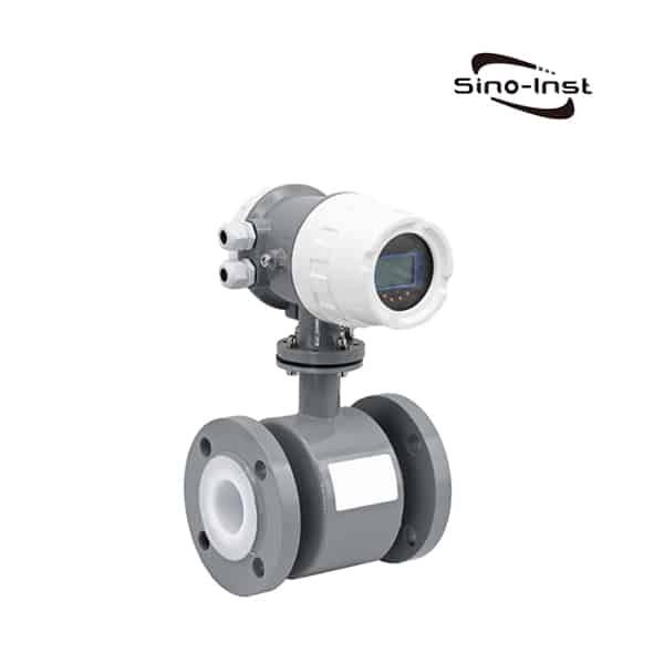
If it is not conductive, it cannot be measured with an electromagnetic flowmeter. Select the appropriate flowmeter according to the size of the flow and the size of the pipeline. From the perspective of medium, it can be measured by liquid turbine flowmeter, vortex flowmeter, oval gear flowmeter, mass flowmeter, orifice flowmeter, and rotameter. Which one is better in practice needs to be selected according to the actual parameters of the site.

Kerosene Gasoline/ Kerosene Flow Meter

Kerosene Gasoline

Pure kerosene is colorless and transparent liquid, pale yellow when it contains impurities. Slightly smelly. The boiling range is 180-310°C (not absolute, it needs to be changed according to the specific situation during production). The average molecular weight is between 200-250.

The melting point is above -40℃. The kinematic viscosity at 40℃ is 1.0~2.0mm2/s. Insoluble in water, soluble in alcohol and other organic solvents. volatile. Flammable. After volatilization, it mixes with air to form an explosive gas mixture. Complete combustion, sufficient brightness, stable flame, no black smoke, no lights, no obvious odor, and little environmental pollution.

Kerosene is miscible with petroleum-based solvents. The solubility of water is very small, and the solubility of kerosene containing aromatic hydrocarbons in water is greater than that of aliphatic hydrocarbon kerosene. Kerosene can dissolve anhydrous ethanol. Mixtures with alcohols separate at low temperatures in the presence of water.

Different uses of kerosene have different chemical compositions. The same kerosene has different physical and chemical properties due to different preparation methods and origins.

The quality of various kinds of kerosene decreases in turn: power kerosene, solvent kerosene, lamp kerosene, fuel kerosene, and washing kerosene.

Kerosene is a high-boiling hydrocarbon mixture with C11-C17 carbon atoms. The main components are saturated hydrocarbons, and also contain unsaturated hydrocarbons and aromatic hydrocarbons. Due to different varieties, it contains 28-48% alkanes, 20-50% or 8%-15% aromatic hydrocarbons, 1-6% unsaturated hydrocarbons, and 17-44% cyclic hydrocarbons. The number of carbon atoms is 11-16. In addition, there are a small amount of impurities, such as sulfides (thiols), colloids, etc. The sulfur content is 0.04% to 0.10%. Free of benzene, diolefins and cracked fractions.

Mainly used for lighting and fuel for various blowtorches, gas lamps, vaporization furnaces and kerosene furnaces; it can also be used as detergent for mechanical parts, solvent for rubber and pharmaceutical industries, ink thinner, cracking raw material for organic chemicals; glass ceramics Industrial, aluminum plate rolling, chemical heat treatment of metal workpiece surfaces and other process oils; some kerosene is also used to make thermometers. According to the use, it can be divided into power kerosene, lighting kerosene, etc.

Extended reading: Quantitative control with turbine flowmeter

Types of Kerosene Flow Meters

Which flowmeter should I choose to measure kerosene flow? We need to understand the corresponding situation of the measurement conditions first. The type of flowmeter that can be selected for different flow ranges can also be different.

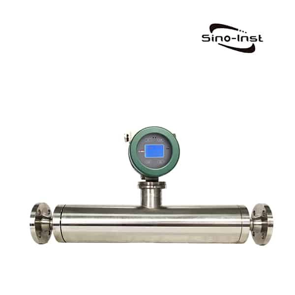
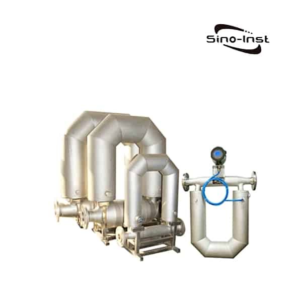
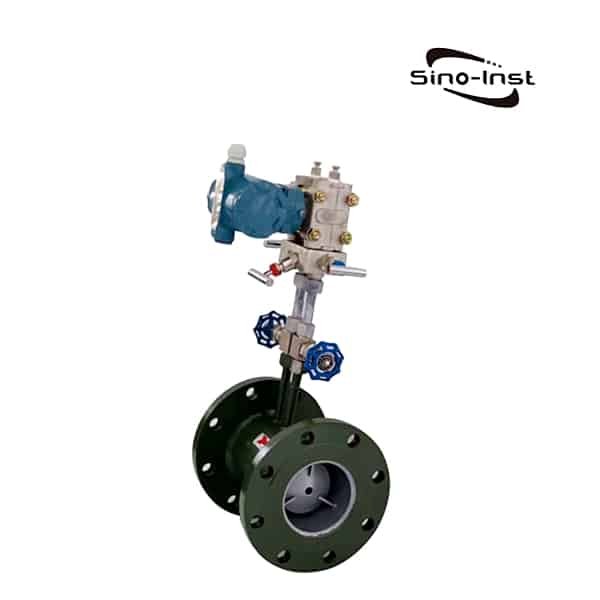
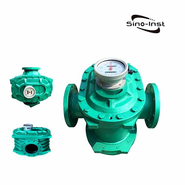
For common measurement sites, trade measurement is generally involved. Our recommendation is to use a liquid waist wheel flowmeter or an oval gear flowmeter. Because volumetric measurement is used, this method measures accuracy. Especially suitable for trade settlement scenarios.

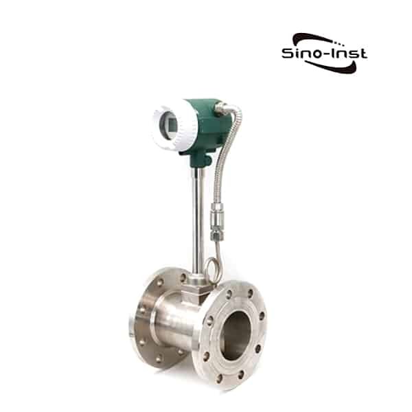
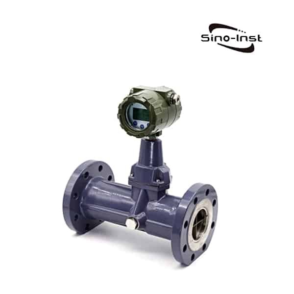
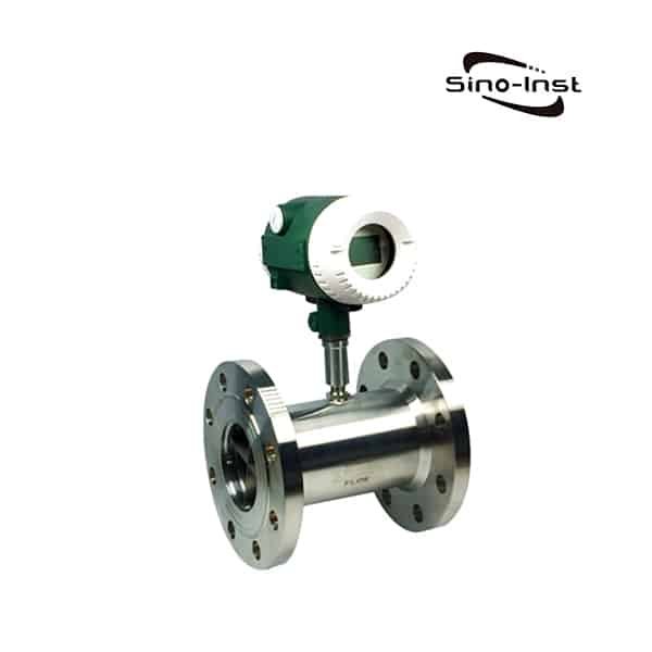
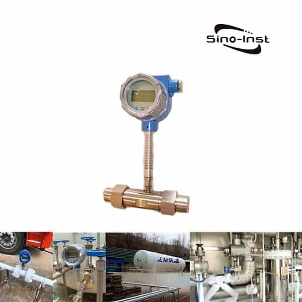
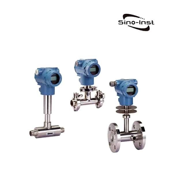
The second is the choice of liquid turbine flowmeter. Turbine flow meters are measured by the rotation of vanes inside the flow. Compared with the volumetric measurement method, the accuracy will be slightly less. But still maintain a stable 0.5 level of accuracy.

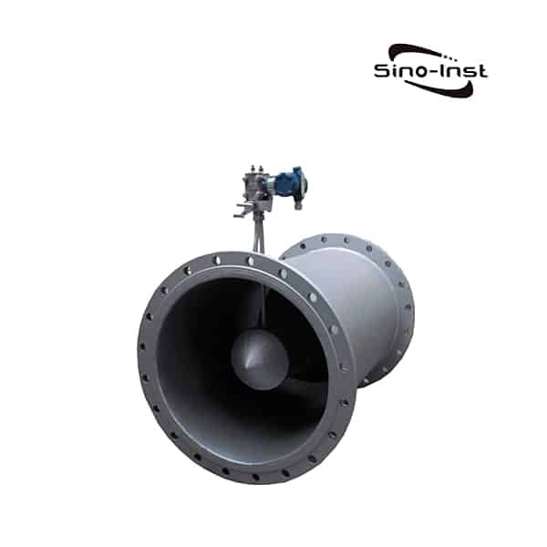
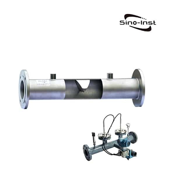
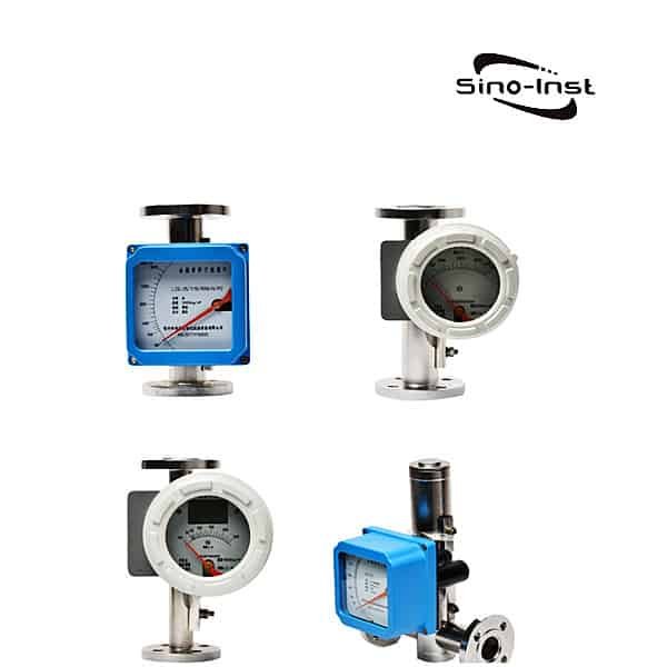
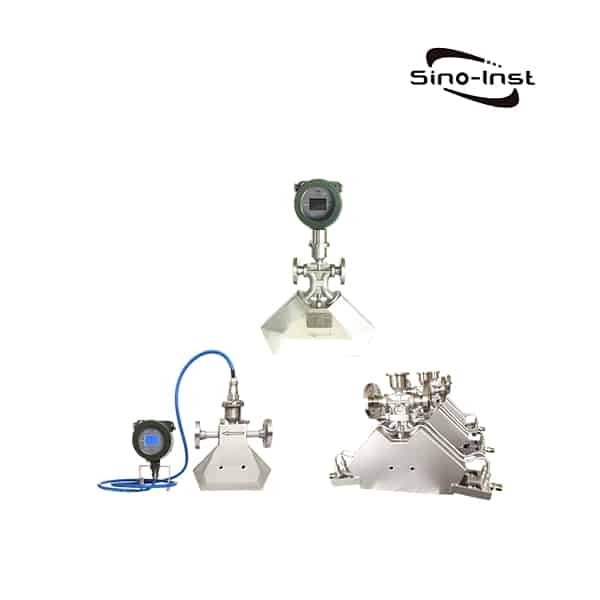
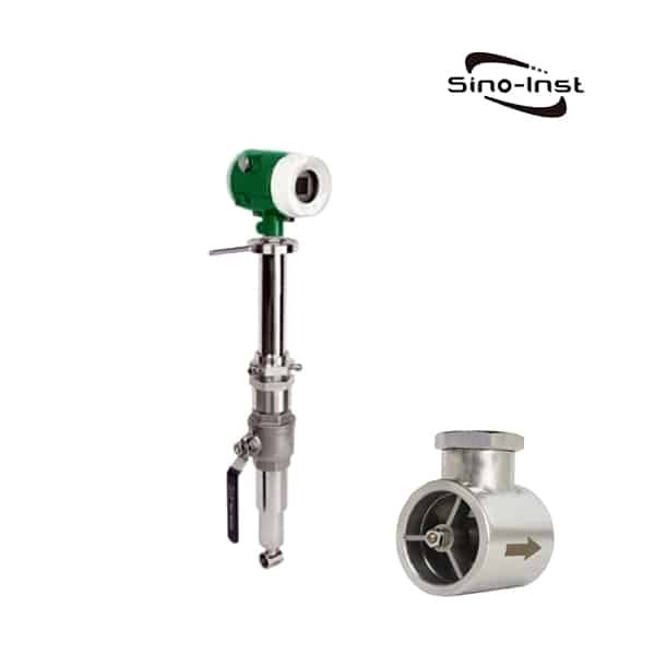
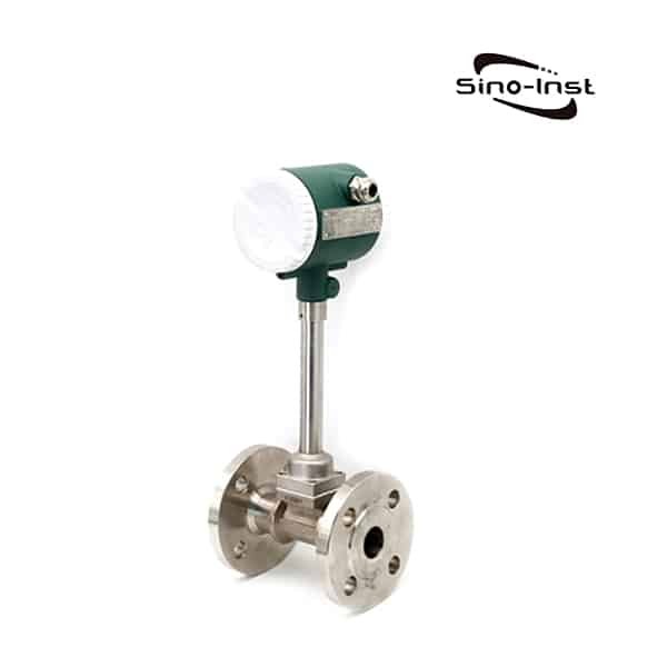
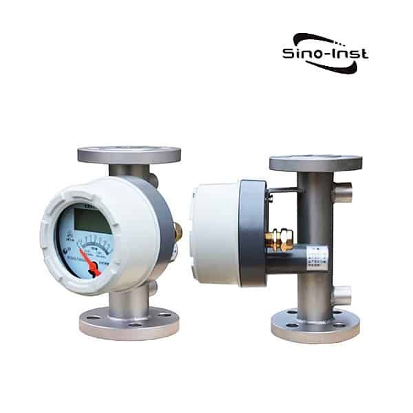
The measurement accuracy of other types of flowmeters, such as metal tube rotameter, orifice flowmeter, and vortex flowmeter, is significantly lower than that of the above two types of flowmeters. It is also optional if it is used for process control or internal monitoring.

Extended Reading: Summary Of Crude Oil Flow Measurement Options

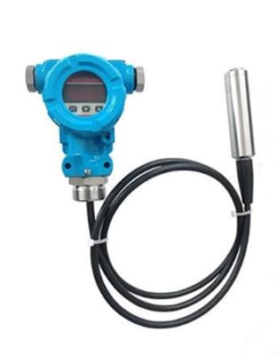
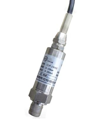
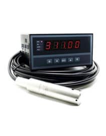
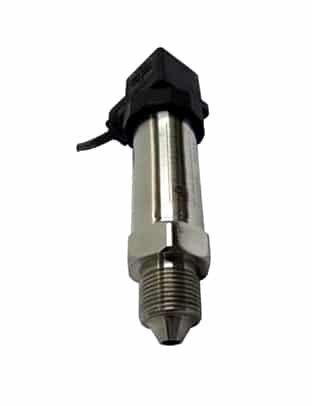
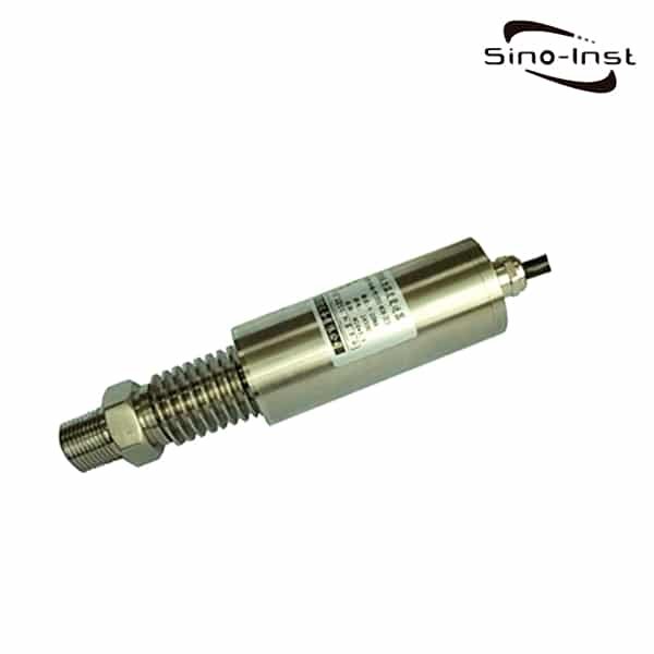
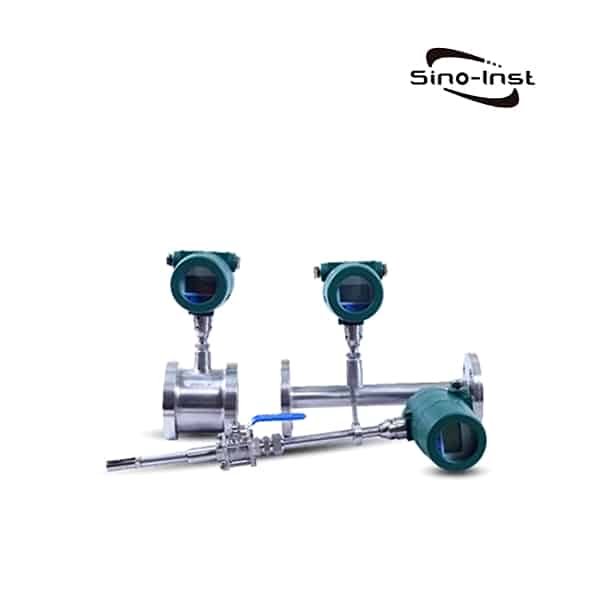
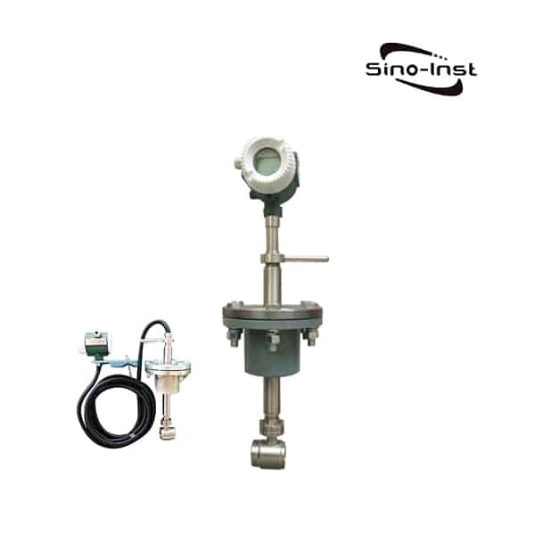
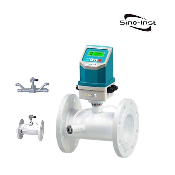
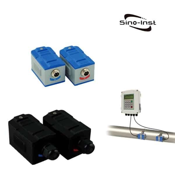
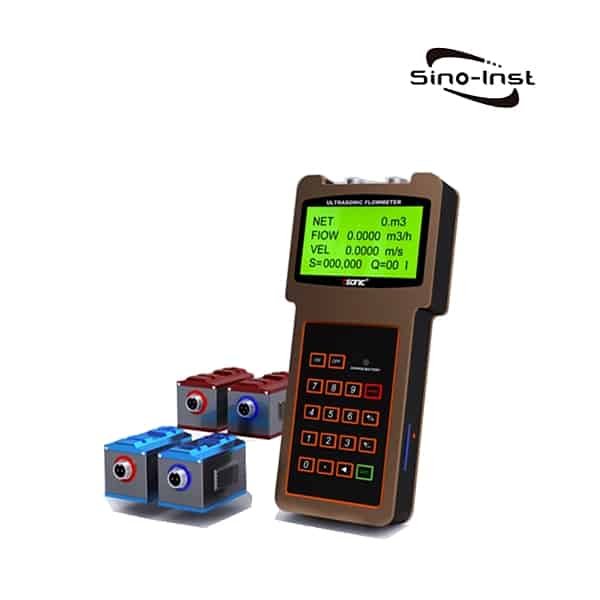
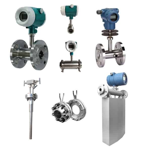
Featured Kerosene Gasoline/ Kerosene Flow Meters

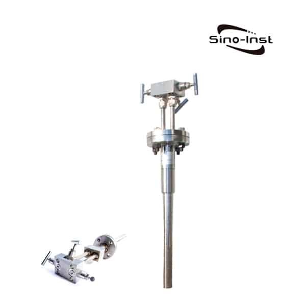
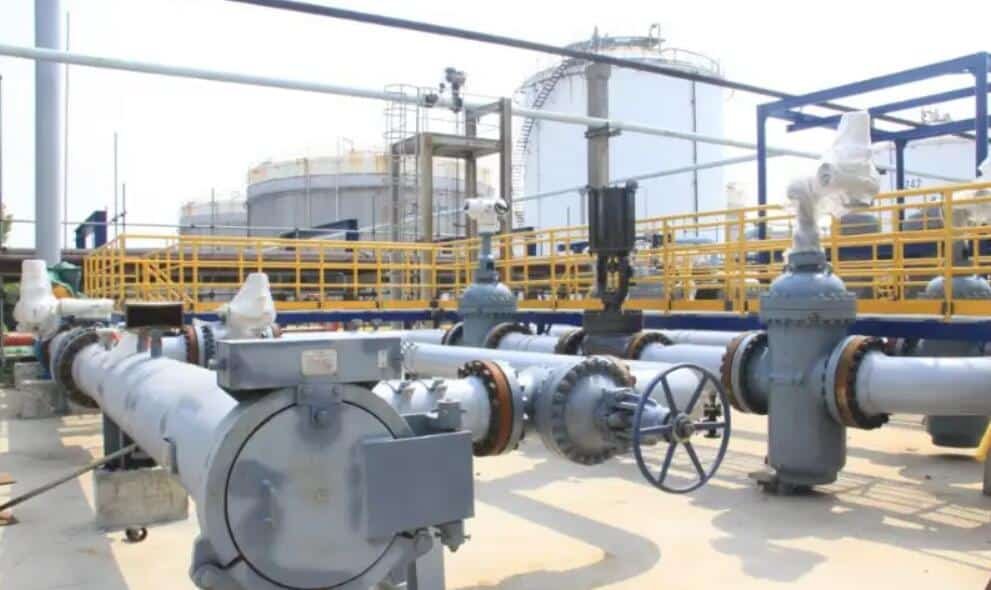
oil and gas flow meter

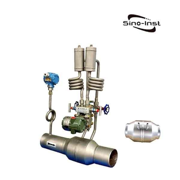
Every day, a large amount of oil and gas are transported back and forth, refined, and then transported, as well as custody transfer. Difficult oil and gas flow measurement challenges such as corrosive media and harsh environments are our daily work. This requires mature and safe technology. Through instrument measurement and display monitoring, safe and reliable operation can be achieved.

Many types of flow meters are used to measure oil and gas flow. Each type has its advantages and disadvantages. The following content discusses these advantages and disadvantages.

Read more about: Flow Meters for Measuring Oil and Gas

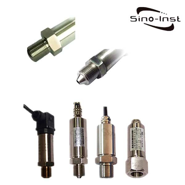
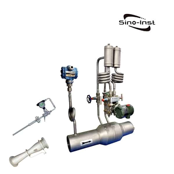
Diesel Fuel Flow Meters

Diesel Fuel flow meters are digital flow meters for liquid fuel consumption measurement.

Most widely used types are mechanical and digital inline fuel meters. Differential flow sensors are avilable. Like: the turbine, positive displacement (oval gear), Coriolis, and differential pressure flow meters.

Sino-Inst offers a variety of fuel flow meters for most fuels. Including diesel, bio-diesel, kerosene, gasonline, oil, heating oil, grease and certain chemicals. Sino-Instrument offers diesel fuel flow measurement solutions and free technical support. If you have any question for diesel fuel flow measurement, please contact us.

Read more about:

Frequently
Asked
Questions

The oil flow meter measures the volume or mass of oil, which can realize the mutual conversion of volume and mass.
There are many types of oil flow meters. Commonly used are turbine flowmeters and dimensional flowmeters.

Extended Reading: Rotameter vs Flow meter

Oil flow meter refers to a type of flow meter that can measure the volume or mass flow of oil. It can be widely used in flow measurement in petroleum, chemical, medical and health departments.

Extended Reading: Industrial petrol flow meters Types

Flowmeter is a professional automatic measuring instrument. Its main function is to measure the flow of fluid, and the measurement medium includes liquid, gas, steam, mixed slurry, solid dust, etc.

It is the special role of flowmeters, in the field of industrial automation, flowmeters and sensors are called the eyes of the automation system. The measurement results are transmitted to the upper computer system. The data is integrated and analyzed by the system. Then the preset scheme is applied to the upstream and downstream control systems to achieve the purpose of intelligent automatic control.

Extended Reading: Petroleum Flow Meter

Commonly used Fuel flowmeters are: turbine flowmeter, gear flowmeter, DP flowmeter and mass liuliangji

Related Blogs

Slurry Flow Meter

Flow Meter for Slurry Application Slurry is a product of domestic sewage and industrial wastewater treatment. Slurry consists of solid impurities, a slurry of suspended substances. The main…

Measuring Steam Flow and Steam Flow Meters

Measuring Steam Flow Measuring Steam Flow is a difficult task. But again, it’s a very important thing. Steam flow measurement is difficult, the main reason is determined by…

Digital Flow Meter for Argon Gas

What is Digital Flow Meter for Argon Gas? Digital flow meter for argon gas refers to a flow meter that can be used for detection, display, transmission, and…

BTU Meter for Chilled Water

What is BTU Meter for Chilled Water? The BTU Meter for Chilled Water accurately measures the thermal energy consumed by chilled water in British Thermal Units (BTU). This…

Guide for Digital Fuel Flow Meter

Digital Fuel Flow Meter is a flow meter dedicated to measuring fuel, diesel, gasoline, and petroleum. Digital Fuel Flow Meter generally has a digital display or signal output…

Mechanical Water Flow Meters

Mechanical water flow meters refer to a type of flow meter suitable for clean water processes or applications. The working principle of a mechanical water flow meter is…

Flow Totalizer Meter vs Flow Meter

A flow totalizer meter is sometimes referred to as a flow meter or flow totalizer. flow totalizer meter displays the flow rate from either an analog or pulse…

Sino-Inst’s Kerosene Gasoline/ Kerosene Flow Meter offer reliable and accurate flow measurement in a large range of sizes and pressure rating while being fully compliant with international standards.

Sino-Inst is the risk-free choice for your Kerosene Gasoline flow measurement applications.

Sino-Inst supplies Kerosene Gasoline/ Kerosene Flow Meters, like: turbine flow meter. vortex flowmeter, thermal mass flow meter, and more.

Sino-Inst’s Kerosene Gasoline/ Kerosene Flow Meters, made in China, Having good Quality, With better price. Our flow measurement instruments are widely used in China, India, Pakistan, US, and other countries.

Request a Quote

Please enable JavaScript in your browser to submit the form

Wireless Level Sensor – LoRa

The Wireless Level Sensor upgrades the LoRa wireless transmission function based on the Hydrostatic Level transmitter. Measure water or oil level. This product adopts the LORA debugging method, which can greatly increase the communication distance. It can be widely used in the field of short-distance Internet of Things wireless communication in various occasions.

Features of Wireless Level Sensor

  • Low power consumption, more than 3 years battery life;
  • -141dBm sensitivity;
  • Long launch distance, up to 10km;
  • Private protocol networking, high security.
  • RS485, Modbus output, compatible with traditional equipment

Specifications of Wireless Level Sensor

Mediumoil, water
TypeAbsolute or gauge pressure
Range0~300m
Precision0.5%FS, up to 0.2%
Output433MHZ
Power supply12~36VDC or battery
Temperature-30~60℃
Storage temperature-40~85℃
Zero drift≤±0.05%FS℃
Full voltage drift≤±0.05%FS℃
Temperature compensation0~70℃
Overvoltage200%FS
Destruction pressure500%FS
Response time≤2ms
Load(Current output)250~1425Ω(Voltage output)≥2KΩ
SealIP68
Long-term stability0.1%FS/Year
Vibrate0.1%FS

Specifications of Wireless parameters

Parameters

Performance

Remark

Operating Voltage

2.4~3.7V


Operating temperature

-40~85℃


working frequency

410–525MHz

434MHz is recommended, which can be configured in the program

Power consumption

launch status

≤100mA(17dBm)

Maximum transmit power

receive status

≤14mA

434MHz

sleep state

≤2uA

434MHz

19 ± 1dBm

User programmable


Modulation

LORA\2-FSK\GFSK\00K

Under LoRa modulation, performance advantages over traditional modulation can be obtained

Communication rate

FSK modulation mode: 1.2~300kbps
00K modulation mode: 1.2~32.768kbps
LoRa modulation mode: 0.2~37.5kbps

User programmable customization, it is recommended to use LoRa modulation method at low rate (<5kbps)

Connect and Install of Wireless Level Sensor – LoRa

LoRa Wireless

LORa is one of the LPWAN (Low Power Wide Area Nerwork) communication technologies. It is an ultra-long-distance wireless transmission scheme based on spread spectrum technology adopted and promoted by Semtech in the United States.

LORa combines digital spread spectrum, digital signal processing and forward error correction coding technology. It has unprecedented performance. Designers can achieve both long distance and low power consumption. Maximize longer distance and lower power consumption The data communication has completely changed the situation in the field of embedded wireless communication.

Wireless Tank Level Sensor

The liquid level transmitter is upgraded by wireless remote transmission. This is an inevitable trend.

The battery-powered Wireless Level Sensor integrates the functions of liquid level acquisition, wireless reporting, and local digital display.

The wireless liquid level transmitter is easy to construct and ready to use. It is mainly suitable for places where power cannot be supplied on site and remote data transmission is required. It can be widely used in liquid level monitoring in urban water supply and drainage, sewage treatment, hydrology and water resources, fire protection, industry and other fields.

From a technical point of view, the Wireless Level Sensors we can currently provide mainly include:

Extended reading: Ultrasonic Oil Level Sensor-External Paste-Truck Fuel Tank

The wireless remote ultrasonic level gauge can adopt two-wire, three-wire or four-wire technology. The power supply circuit and the signal output circuit are independent.

When using DC 24v power supply, a 3-core cable can be used, and the negative end of the power supply and the negative end of the signal output share a core wire.

When using AC 220v power supply, or when using DC 24v power supply. When the power supply circuit and the signal output circuit are required to be completely isolated, a 4-core cable should be used. DC or AC power supply, with 4~20mADC, high and low switch output.

Read more about: How to Choose Explosion Proof Ultrasonic Level Sensor?

The wireless radar level gauge has the advantages of no blind area, non-contact measurement, and is not affected by the physical characteristics of the measured medium. In recent years, it has been widely used in the field of petroleum and petrochemical.

Smart wireless technology eliminates the need for long-distance wiring in trenches and bridges. Save material, reduce labor costs, and reduce engineering and project execution time.

Smart wireless technology also makes automated user management easier, faster, and less expensive.

Integrating tank level gauges with smart wireless technology can reduce system installation costs by up to 50% by wirelessly connecting storage tank farms and control rooms. And can also reduce implementation time by up to 60%. The budget required to retrofit the automation of the storage tank farm is greatly reduced.

Wireless radar level gauge through Wireless Hart signal to wireless 1420 gateway;
1420 wireless gateway and the seamless integration of the host system;
The host system can be DCS, PLC, HMI.
The communication method between them can be Ethernet, Modbus, OPC.

Extended reading: Corrosive Liquid Chemical Level Sensor in Chemical Processing

chemical tank level sensor

Liquid chemical level sensor is suitable for chemical storage tanks or chemical processing. Especially for highly corrosive liquids.

In chemical storage tanks or chemical processes, there is a risk of corrosive liquids and explosions. Therefore, the requirements for the liquid level indicator are extremely high. SIRD-702 liquid chemical level sensor is a corrosion-resistant guided wave radar level sensor. The maximum range of anti-corrosion guided wave radar level meter can reach 20 meters. It is used to measure the liquid of strong acid and strong alkali. Such as hydrochloric acid, sulfuric acid, hydrofluoric acid, strong alkali and sodium hydroxide. SIRD-702 liquid chemical level sensor adopts all PTFE sealed cable or rod antenna.

Extended reading: Applicaitons Of Magnetostrictive Level Transmitters

Water Level Monitoring System

The Water Level Monitoring System is mainly composed of a telemetry station (Wireless Level Sensor, or wired level transmitter, etc.) and a platform management center.

The telemetry station mainly monitors real-time water level, rainfall, on-site images and other data information in various regions, and uploads it to the platform management center.

The platform management center receives and processes the data sent by the telemetry station through the monitoring and early warning platform, and warns decision makers of decision-making information according to their needs.

At the same time, the system can quickly release relevant early warning information through WEB, mobile terminal, SMS and other means. The Wireless Level Sensor system is a typical IoT system.

Frequently
Asked
Questions

The wireless remote control water level controller is mainly an intelligent instrument designed for long-distance water tower and mountain top pool water level monitoring. It can not only monitor the change of water level, but also automatically control the start and stop of the water pump.

There are generally three parts, namely the water depth sensor, the transmitter and the receiver.

The transmitter is installed in the water tower. The receiver is installed in the control center. When the sensor is put into water, its output voltage is proportional to the water depth. The higher the water level, the higher the output voltage.

under the control of sequential circuits. Its water depth signal is transmitted to the receiver of the control center through the transmitting antenna. The receiver displays the water level data under the control of the program. And according to the set water level upper and lower limit value and water level alarm value, control the opening of the water pump, and send out the over-limit alarm signal in time.

Extended reading: water meter installation details

The water tank level monitoring system is widely used in various landmark buildings to complete the automatic water level display and alarm system of the fire water tank. All that is put into the liquid is a liquid level pressure sensor probe. The circuit part is in the junction box on the other end. It is convenient for users to adjust.

There are two types of installation methods: M20 x 1.5 thread installation and DN50PN0.6MPa (GB9119-88) standard flange installation. The display instrument is placed in the control room to display the water level of the pool in real time.

Extended reading: Float Switch Water Level Controller

Related Products

Related Blogs

High Temperature Pressure Transducer with Best Price

High Temperature Pressure Transducer is also called High Temperature Pressure Sensor, or High Temperature Pressure Transmitter. The High Temperature Pressure Transducer is used for applications where the medium temperature exceeds…

Water Level Transducers – Detailed Guide

What Is a Water Level Transducer? Water level transducers are also called Water Level Sensors, or water level transmitters. Water level transducers are used to monitor water usage and quality…

New Trend of Transformer Oil Level Indicator

What is Transformer Oil Level Indicator? The Transformer oil level indicator is specially designed to measure and indicate the oil level in transformer tanks, oil conservators and on-load tap-changers. Transformer…

External Tank Level Indicator

External Mounted Tank Level Sensors External Tank Level Indicator refers to an externally mounted level sensor. It is used to install on the outside of the liquid storage tank to…

80GHZ Radar Level Transmitter

80 GHz Radar Level Measurement 80GHZ Radar Level Transmitter refers to a frequency modulated continuous wave (FMCW) radar product operating at 76-81GHz. It can be used for level measurement of…

Material Level Indicators

The material level indicator refers to an instrument for real-time detection of changes in the height of solid materials in a container. Material level indicator is also known as material…

What is Static Water Pressure?

What Is Static Water Pressure? Definition of Static Water Pressure: Static Water Pressure refers to the pressure on water when it is stationary or moving in a straight line at…

The Secret of Water Level Control

Water level control refers to the control of high and low water levels by mechanical or electronic methods. It can control solenoid valves, water pumps, etc. to become an automatic…

Sino-Inst offers over 20 Wireless Level Sensors. A wide variety of  Wireless Level Sensors options are available to you. Such as free samples, paid samples. 

Sino-Inst is a globally recognized manufacturer of Wireless Level Sensors, located in China.

Sino-Inst sells through a mature distribution network that reaches all 30 countries worldwide. 

Wireless Level Sensors products are most popular in Europe, Southeast Asia, and Mid East. You can ensure product safety by selecting from certified suppliers. With ISO9001, ISO14001 certification.

Request a Quote

Please enable JavaScript in your browser to submit the form

High Temperature Pressure Transducer with Best Price

High Temperature Pressure Transducer is also called High Temperature Pressure Sensor, or High Temperature Pressure Transmitter.

The High Temperature Pressure Transducer is used for applications where the medium temperature exceeds the temperature limits of standard pressure transmitters.

By assembling Cooling Elements of different lengths, the temperature of the measured medium can be further improved. Reasonable and scientific configuration, advanced circuit design and temperature compensation processing fully ensure that the transmitter can work stably for a long time in a high temperature environment.

Examples include high temperature pressure monitoring for steam, food processing and engine monitoring.

Featured High Temperature Pressure Transducers for Sale

High Temperature Pressure Transducer Specifications

Range:0~1KPa~10KPa~400KPa, -0.1 ~ 0 ~ 1 ~ 60 (MPa), 0 ~ 10KPa ~ 100MPa
Comprehensive accuracy:0.25% FS, 0.5% FS
Output signal:4-20mA (2-wire system), 0-5 / 1-5 / 0-10V (3-wire system) Other customized output signals
Power supply voltage:24DCV (9 ~ 36DCV)
Medium temperature:-30 ℃ ~ 160-350 ℃, customized up to – 300~850 ℃.
Ambient temperature:Normal temperature (-20 ~ 85 ℃)
Load resistance:Current output type: maximum 800Ω; voltage output type: greater than 50KΩ
Insulation resistance:Greater than 2000MΩ (100VDC)
Long-term stability:0.2% FS / year
Vibration effect:In the mechanical vibration frequency 20Hz ~ 1000Hz, the output change is less than 0.1% FS
Electrical interface:bare wire; Hessman connector (customizable) Or customized size
Thread connection:M20 × 1.5, etc. Other threads can be designed according to customer requirements
Dimensions:M20 × Φ26.5 × 156 Or customized size
Shell protection:Plug type (IP65); cable type (IP67)
Safety explosion-proof:Ex iaⅡ CT5
Zero Temperature Drift0.05% per 10 degrees
Range Temperature Drift0.05% per 10 degrees
Safety Overload3 times overload
Ultimate Overload3 times overload
Response Time0.1s

Extended reading: High Pressure Flow Meters for Liquids-Steam-Gas

Ultra High Temperature Pressure Sensor

The ultra-high temperature pressure transmitter adopts special imported materials, isolated diaphragm design, and water circulation cooling method. The temperature of the measuring medium can reach 1300 ℃.

It is suitable for pressure measurement and control of high temperature media such as engine gas and kiln.

Such sensors are also commonly referred to as:
Ultra-high temperature pressure transmitter, ultra-high temperature pressure sensor, fuel pressure sensor, furnace pressure sensor, water-cooled pressure sensor, water-cooled pressure transmitter.

Extended reading: Heating Oil Flowmeters

Technical Difficulties in Pressure Measurement at High Temperature

High temperature conditions have certain requirements on the material, process and performance of the pressure transmitter. In order to ensure the measurement of High Temperature Pressure Transducer, we need to pay attention to the following points.

  1. Fully welded pressure transmitter.
    All connections between capillaries, transmitters and process connections are of fully welded hermetic construction. to eliminate possible leak points.
  2. According to different applications, the amount of filling oil can be precisely controlled.
    According to the user’s application and the characteristics of different filling oils. After careful calculation. Appropriately reduce the amount of filling oil. To compensate for the expansion effect of the filling oil.
    For low temperature applications, the amount of filler oil can be appropriately increased according to the specific application. to compensate for the effect of volume shrinkage of the filler oil.
  3. Special oil replenishment and oil discharge treatment.
    The main purpose of oil pretreatment for filler oil is to reduce dissolved gas content.
    And in the process of oil filling, vacuum oil filling is used. And strictly control the oil filling amount when the oil reaches the vacuum degree requirement. Guarantee the measurement accuracy of the final product.
  4. In modern technological processes, high temperature pressure transmitters often adopt symmetrical designs. Same diaphragm, same capillary length and same oil-filled fluid on both high and low pressure ends.
    It is generally believed that when the effect of temperature change acts on the high and low pressure sides of the transmitter. This effect will be eliminated. The effect of temperature on the diaphragm is generally considered to be the most important cause of temperature drift. In fact, the opposite is true.
    • Using the same length of capillaries on the high and low pressure sides did not improve performance. Instead, it increases the impact of temperature changes on the overall performance of the transmitter.
    • Pressure transmitters are temperature dependent not only by the amount of temperature change of the diaphragm of the base product. The length of the capillary is also an important factor affecting the temperature change of the transmitter. And the hardness is proportional to the length of the capillary.
    • The high and low pressure sides use the same capillary length, which is twice the length of the capillary. This increases the effect of temperature on the overall performance of the transmitter.
    • That is, if the process temperature is 150°C or less and the process conditions allow it. Then remove the high side port capillary and connect directly to the transmitter. The length of the capillary can be shortened. Reduce the impact of temperature changes on transmitter accuracy and response time.
  1. Choose according to the chemical properties of the measuring medium.
    • The corrosiveness of the same medium with different concentrations at different temperatures is also different.
    • Diaphragm sealed pressure transmitter, generally the inner diaphragm box is made of stainless steel. Wetted outer capsules are selected according to the characteristics of the medium.
    • At present, the commonly used materials are 316L, Monel, hafnium alloy and Tan diaphragm.
      Consider the housing material of the pressure transmitter according to environmental conditions and economy. Shell materials generally include aluminum alloy and stainless steel. If not in highly corrosive environmental conditions. It is more economical to choose aluminum alloy material.

Extended reading: How do you calibrate a smart pressure transmitter?

High Temperature Differential Pressure Transmitter

The high temperature differential pressure transmitter is only an instrument that can be used to measure the differential pressure of the medium under high temperature conditions.

It can work stably at 600℃ ultra-high temperature for a long time. Maintain the same high precision, high reliability and high stability as conventional single crystal silicon transmitters. Cost-effective. These three factors are the difficult points of Sino-inst technology research.

The brief principle of remote differential pressure transmitter for measuring 600℃-800℃ ultra-high temperature medium pressure is as follows:

The outer end faces of the connecting flange and the isolation flange are welded with the measuring diaphragm (meeting the requirements of the diaphragm’s resistance to medium corrosion) and the isolation diaphragm (conventional 316L diaphragm).

The heat sink is welded between the connection flange and the isolation flange, and then the ultra-high temperature resistant high-viscosity high-temperature filling liquid is injected to form an ultra-high temperature filling liquid cavity.

Weld the mating flange on the other end of the spacer flange. Connect capillary and pressure transmitter, differential pressure transmitter. Inject low-viscosity high-temperature filling fluid to form an ordinary high-temperature filling fluid cavity.

When working, the pressure of the ultra-high temperature medium is transmitted to the isolation diaphragm through the ultra-high temperature-resistant high-viscosity high-temperature filling liquid.

Then, the pressure of the ultra-high temperature medium is transmitted to the pressure transmitter and the differential pressure transmitter body through the low-viscosity high-temperature filling liquid in the capillary. Realized pressure transmission and measurement.

With high-temperature isolation and heat dissipation, ultra-high temperatures are not directly transferred to low-viscosity, high-temperature fill fluids. Thereby protecting the high temperature remote pressure transmitter and differential pressure transmitter. The pressure measurement of ultra-high temperature medium is realized.

Especially in the power generation system with molten salt as the heat transfer medium. The molten salt temperature as high as 560°C and the corrosiveness of molten salt have put forward higher requirements for pressure transmitters.

Utilizes a combination of ultra-high temperature silicone oil and an internal isolating diaphragm. The application temperature of the site is greatly increased to about 600 ℃. Greatly expands the application range of ultra-high temperature pressure/differential pressure measurement. It can be widely used in coal chemical industry and solar thermal power generation industry.

The selection ideas and methods of 600°C ultra-high temperature remote pressure transmitter/remote differential pressure transmitter are the same as those of conventional single crystal silicon remote pressure transmitter and remote differential pressure transmitter, and will not be repeated here. .

If you encounter high temperature measurement problems, welcome to communicate with Sino-Inst.

Extended reading: Industrial Pressure Transmitters|Buy from the manufacturer

Cooling Element

Cooling Element is mostly used in pressure gauges and High Temperature Pressure Transducers.

Cooling elements should be constructed of stainless steel to provide maximum corrosion resistance to most process media.
Female thread 20×1.5 and male thread 20×1.5 are standard.
Also supports customized according to customer requirements.

Extended reading:  Tri Clamp Sanitary Thermometers


Combined pressure and temperature sensor for Simultaneous measurement of pressure and temperature.

The Combined pressure-temperature sensor uses a special core. Thermocouple types are: J, K, E type or PT100 platinum resistance. Integrated structure of temperature and pressure. Measure the medium pressure and temperature at the same point at the same time. The combined pressure and temperature sensor has a built-in temperature / pressure sensor. The two outputs do not affect each other. Consuming the power of one sensor can complete the pressure and temperature measurement. Widely used in scientific research, military industry, petrochemical, electric power, metallurgical machinery and environmental protection fields. Such as oil well temperature and pressure measurement, diesel engine common rail temperature and pressure measurement, injection machinery temperature and pressure measurement.

Extended reading: Flat Pressure Sensor for High Viscosity Fluids

Frequently
Asked
Questions

Yes. Temperature affects pressure transducers.
Temperature has a major impact on the functionality and operating life of most electronic devices. This is especially true for electronic pressure sensors.

This is why pressure sensor specifications generally include small and large values for operation, storage, and compensation of medium temperature. Exceeding these ranges can introduce unexpected errors in pressure readings. Or in extreme cases, leading to the failure of the complete instrument.

Another temperature specification – calibration temperature – can also be included in the data sheet.

Extended Reading: Selection of pressure transmitter

High pressure transducer is used to measure high pressure up to 1500Mpa. Also called ultra high pressure transducer.

High pressure transducer adopts ultra high pressure design. Suitable for high pressure applications up to 15000bar. SI-702S series ultra high pressure pressure transducer can provide reliable ultra-high pressure measurement. Ultra high pressure transmitter adopts rare metal alloy material. After special process treatment, integrated design. All stainless steel welding package. Laser resistance temperature compensation. With high performance digital processing circuit. The factory has undergone high and low temperature aging and long-term fatigue tests. Good long-term stability. Ultra-long working life. Maintain safe and stable operation in the ultra-high pressure range.

This depends on the user’s highest pressure requirements. Our common pressure transmitters also have a certain pressure range. If the customer is ultra-high pressure, such as 700MPa or even higher pressure. Sino-Inst supports customization.

Related Products

Related Blogs

Water Level Transducers – Detailed Guide

What Is a Water Level Transducer? Water level transducers are also called Water Level Sensors, or water level transmitters. Water level transducers are used to monitor water usage…

The Myth of Ceramic Pressure Sensor

What is a ceramic pressure sensor? Ceramic pressure sensors are sensor diaphragms made of ceramic alumina (Al2O3). Ceramic is a material with high elasticity, corrosion resistance, wear resistance,…

How to convert a 4-20mA to 0-10V /1-5V signal?

4-20mA to 0-10v voltage, this is I/V conversion. That is current-voltage conversion, usually used for long-distance signal transmission in the industry. How to convert a 4-20mA to 0-10V…

What does intrinsically safe mean?

Intrinsically safe type is an explosion-proof type of electrical equipment. When purchasing electrical equipment, do you often hear about intrinsic safety? For example, when ordering pressure transmitters or…

Static Pressure/Hydrostatic Pressure Transmitter

The Hydrostatic Pressure Transmitter measures the hydrostatic pressure exerted by a hydrostatic head. Use these hydrostatic pressure transmitters to measure the liquid level in storage tanks, processing vessels,…

What is Static Water Pressure?

What Is Static Water Pressure? Definition of Static Water Pressure: Static Water Pressure refers to the pressure on water when it is stationary or moving in a straight…

What is a pressure sensor?

What is a pressure sensor? A pressure sensor is a device that senses a pressure signal and converts the pressure signal into a usable output electrical signal according…

What does SCADA stands for?

What does SCADA stand for? SCADA is the abbreviation of Supervisory Control And Data Acquisition. Namely data acquisition and monitoring control system. SCADA system is also called monitoring…

High Temperature Pressure Transducers are used in applications, where the media temperature exceeds the temperature limits of standard pressure transmitters.
Or where it is not possible to fit a standoff pipe,
pigtail or other cooling devices to reduce media temperature.

As high temperature pressure transducer manufacturer, Sino-Instrument supplies High Temperature Pressure Transducer with Best Price.

For example:
High Temperature Pressure Transducer, measure high temperature liquid, high temperature 300 degrees. The reference price is USD 200.00/pc.
High Temperature Pressure Transducer, measuring compressed air, high temperature 800 degrees. The reference price is USD 790.00/pc.

Tolerant to high-temperature applications such as steam, food processing & engine monitoring.

If you have a special request, you can just contact us for Technical Support.

Request a Quote

Please enable JavaScript in your browser to submit the form

Water Level Transducers – Detailed Guide

What Is a Water Level Transducer?

Water level transducers are also called Water Level Sensors, or water level transmitters. Water level transducers are used to monitor water usage and quality. The water level signal is output through 4-20mA and other signals, which is convenient for people to monitor the water level.

There are many types of water level transducers. Common ones are input type, ultrasonic, radar and so on.

Sino-Inst offer a wide range of solutions with various pressure ranges, cable lengths and output options.

For remote monitoring and recording of water level data in groundwater pumping and sludge testing, stormwater flood analysis and runoff, and surface water irrigation canals, streams and river measurements.

Featured water level transmitters for Sale

level transducer types

In various industrial production processes, many auxiliary safety products are used. Among them, level transducer, as one of the most common auxiliary products, has many names. The following are 20 common level transducers:

  • Magnetic flap liquid level transducer
  • Float level transducer
  • Steel belt level transducer
  • Radar level transmitter
  • Magnetostrictive liquid level transducer
  • RF Admittance Level Transducer
  • Tuning Fork Level Meter
  • Glass plate/glass tube level transducer
  • Hydrostatic level transmitter
  • pressure level transmitter
  • Capacitive Level Transducer
  • Intelligent electric displacer liquid level transducer
  • Buoy Level Transducer
  • Displacer Level Transmitter
  • Electric contact level transducer
  • Magnetic two-color electronic liquid level transducer
  • External level transmitter
  • Hydrostatic Level Transducer
  • Ultrasonic Level Transducer
  • Differential pressure level transmitter (double flange level transmitter)

Extended Reading: What is level transmitter working principle?


types of water level sensors

We can divide Water Level Sensors into two categories by measuring whether they are in contact with the water level.

One type is contact type. Including single flange static pressure/double flange differential pressure level transmitter, float type level transmitter, magnetic level transmitter, input type level transmitter, electric internal float level transmitter Sensors, electric float level transmitters, capacitive level transmitters, magnetostrictive level transmitters, service level transmitters, etc.

The second category is non-contact. Divided into the ultrasonic level transmitter, radar level transmitter, and so on.

Extended Reading: Chilled Water Flow Meter

Submersible level transmitter is a kind of Hydrostatic water pressure level transmitter. It is widely used for its simple installation and reasonable price. Providing quick, accurate and reliable level measurement.

Cable 0m ~ 300m, minimum range 0.5m.

Submersible Water Level Sensor Specifications

Measurement form and range0~1~200mH2O
Overload allowed3 times full scale pressure
Operating temperature-20~80℃
Temperature compensation-10~70℃
Storage temperature-40~80℃
Accuracy (including nonlinearity, repeatability, hysteresis)0.2%FS(Typical) 0.5%FS(Maximum)
Stability error0.2%FS(Typical), 0.5%FS(Maximum)
Temperature drift coefficient0.01%FS (typical, range not less than 5mH2O)
0.03%FS (typical, less than 5mH2O)
Output signal(4~20)mA, (0~10/20)mA
(0~5)V, (1~5)V, )0~10)V
Power supply15~36 VDC (calibration voltage 24VDC)
Load (Ω)Current output type<(U-15V)/0.02A, current output type>5K
Shell materialStainless steel
O-ringFluorine rubber
Diaphragm316L stainless steel
CableSpecial waterproof and breathable cable
Protection classIP68 (pressure sensor part), IP65 (junction box transmitter part)

Learn More About Submersible Level Transducer

Radar sensor for water level is a level detection instrument using microwave technology. It is mainly suitable for detecting the water level of natural waters such as rivers and lakes. It can also be used for water level detection of large reservoirs, reservoirs, sewage canals and other open-air channels.

As a detection terminal, this product can effectively assist in monitoring the state of water level changes and provide accurate water level information for monitoring units.

Extended Reading: LORA water meter

The product adopts the pulse radar detection method, which can work stably around the clock. The measurement results are accurate and reliable.

The non-contact detection method makes its application range more extensive. It can even be used in complex water environments with organic pollutants or sediments.

Application: Rivers, Lakes, Shoal
Measuring Range: 70 meters
Process Connection: Thread G1½ A″ /Frame /Flange
Temperature: -40℃ ~ 100℃
Process Pressure: Normal pressure
Precision: ± 3mm; ± 10mm
Frequency Range: 26GHz
Protection Grade: IP67 / IP65
Power Supply: (6 – 24V) DC  / Four-wire
24V DC / Two wire
The Signal output: RS485 / Modbus ( 6~24V DC)
4~20mA / Hart Two wire ( 24V DC)
The Scene Display: Optional
Outer Covering: Aluminum / Plastic / Single chamber

Extended reading: Amazing Solutions for Continuous Liquid Level Measurement

The principle of liquid level measurement of pressure sensor

In physics, the pressure P of a liquid is determined by the relationship: p=ρgh.

For the same liquid, the liquid density ρ is constant. Therefore, the pressure P of the liquid is linearly proportional to the height h of the liquid surface (the height from the liquid surface). It is not difficult to find that the pressure of the liquid at different heights of the liquid level is also different.

When the pressure sensor is used to measure the liquid level, the pressure sensor is installed at the bottom of the tank. When the liquid level in the tank changes, the height h from the tank bottom to the liquid level is also changing at the same time. The pressure will naturally change accordingly. Thus, the purpose of continuous measurement is achieved.​​

One of the advantages of using pressure sensors for liquid level measurement is non-contact. Compared with mechanical and static methods, when measuring, it does not require many parts to be in contact with the liquid, and the installation is relatively convenient.

In addition, in terms of measurement principle, compared with similar non-contact measurement methods such as laser and ultrasonic, the relationship between pressure sensor measurement principle is simpler and linear, and it is more intuitive in data processing, analysis and processing.

Extended reading: Float Switch Water Level Controller

How does a water level transducer work?

Water level transducer is an instrument that can convert the water level parameter of the measured point into the corresponding electric quantity signal in real time.

The working principle of the Water level transducer is that when it is put into a certain depth in the liquid to be measured. The pressure on the sensor’s front surface is converted into the liquid level height.

The calculation formula is Ρ=ρ.g.H+Po.

In the formula P is the pressure on the liquid surface of the sensor;
ρ is the density of the liquid to be measured;
g is the local acceleration of gravity;
Po is the atmospheric pressure on the liquid surface;
And H is the depth at which the sensor drops into the liquid.

Extended reading: How to convert a 4-20mA to 0-10V /1-5V signal?

industrial water level sensor advantages and disadvantages

At present, the Submersible Water Level Sensor is the most used one.

Submersible Water level transducers generally use the piezoresistive effect of diffused silicon or ceramic sensing elements. Convert static pressure into electrical signal. Temperature compensated and linearity corrected. Converted to 4-20mADC standard current signal output.

The Submersible Water level transducer is directly put into the liquid, and the transmitter part can be fixed by flange or bracket, which is extremely convenient to install and use.
​​
The benefits of water level sensors

  • Good stability and high precision;
  • The Submersible Water Level Sensor is put directly into the measured medium. It is very convenient to install and use;
  • Input type, straight rod type, flange type, threaded type, inductive type, screw-in type, floating ball structure design. Anti-blocking design is available.
  • Simple installation, convenient use and strong interchangeability. High-quality level gauges have high sensitivity.
  • The response speed is fast, and it accurately reflects the subtle changes of flowing or static liquid level.
  • High measurement accuracy.
  • Solid-state structure, no moving parts, high reliability.
  • Long service life High-precision measurements are possible from water and oil to more viscous pastes.
  • A wide range of temperature compensation is not affected by the foaming, deposition, and electrical properties of the measured medium.
  • The Submersible Water Level Sensor has power reverse polarity protection and overload current limiting protection.

The disadvantages of Submersible Water Level Sensor are:

  • The measurement signal needs to be converted;
  • Cannot measure the temperature of high temperature medium over 125℃;
  • The density of the measuring medium must be uniform.

These points also limit its scope of use. But for water level measurement, Submersible Water Level Sensor is the perfect choice.

Extended Reading: 3 inch (3″) Water Meter

water level sensor applications

Uses of water level sensors include the following applications:

  • Water level measurement in pools and tanks
  • River and lake water level measurement
  • Marine level measurement
  • Level measurement of acid and alkali liquids
  • Oil level measurement of oil trucks and mailboxes
  • Swimming pool water level control
  • Tsunami Warning and Sea Level Monitoring
  • Cooling tower water level control
  • Sewage pump level control
  • Liquid level remote monitoring

Extended reading: Sludge Blanket Level Detector Appliactions

The river water level monitoring system is an important means to grasp the changes of river water conditions in real time, scientifically warn flood disasters, improve flood control command ability, and reduce the losses of rain and flood disasters.

System functions:

  • Real-time monitoring of river water level, expandable monitoring of rainfall, water quality and flow velocity.
  • Support remote photography or video real-time monitoring (video communication).
  • When the water level exceeds the limit, the sensor fails, and the battery voltage of the monitoring terminal is low, it will alarm immediately.
  • Automatically generate water level process curves and data statistical reports.
  • It can be linked with the drainage pump station. Automatically control the start and stop of the drainage pump group according to the water level of the river.
  • Support through OPC, database and other forms. Docking with other comprehensive monitoring application platforms.

The river water level monitoring system is compatible with various water level gauges such as ultrasonic, radar, float, laser, bubble, and input type.

Extended Reading: Low Cost Float Level Sensor for Tank Liquid Volume Monitoring

The reservoir/lake water and rain monitoring system is suitable for the water management department to remotely monitor the real-time data and on-site images such as the water level and rainfall of the reservoir/lake. In order to keep abreast of the changes in the water storage capacity of the reservoir/lake, to ensure moderate water storage and safe flood season.

  • Real-time monitoring of water level and rainfall of reservoirs/lakes, and timely grasp of water storage conditions
  • During optical fiber/5G/4G/3G communication, it supports real-time video surveillance. During 2G communication, it supports remote photography.
  • When the water level, rainfall exceeds the limit or the on-site equipment fails, it will automatically alarm and send an alarm text message to the mobile phone of the watchman. Automatically generate water level, rainfall time, day, month, year statistical reports and analysis curves.
  • Provide system interface. Support integration into the upper-level flood control and drought relief command system

Extended reading: Ultrasonic Water Meter Working Principle

digital water level recorder

Paperless Recorder is an intelligent Digital chart recorder. Data can be remotely recorded, analyzed, stored, and signal output. LCD color screen, maximum 16 channels.

R7100 series color paperless recorder supports 1-16 channels of universal input. R7100 has a powerful display function, real-time curve display, historical curve recall, bar graph display, alarm list display, power-down list display.

Configurable and optional inputs: standard voltage, standard current, thermocouple, thermal resistance, frequency, switch value, pulse, etc. It can be equipped with 6 relay alarm outputs, 6 feed outputs, 4 transmitter outputs, and RS232/485 communication interface is optional. Bluetooth function, GPRS function Ethernet interface, micro printer interface and USB interface.

Sino-Inst offers a variety of digital water level recorder instruments for industrial control. If you have any questions, please contact our sales engineers.

Frequently
Asked
Questions

Level transducers are generally used where liquid level measurements need to be measured, and are suitable for liquid level and interface measurement of liquid media in containers. Level transducer is suitable for liquid level measurement of various media in petroleum, chemical, metallurgy, pharmaceutical and other industries.

Most of the measurement objects of Level transducers are liquid media. Because the objects to be measured are different, the measurement methods are also different. Therefore, Level transducers can be divided into many types. For example, there are ultrasonic liquid level sensors, input liquid level sensors, Magnetic flap liquid level sensor, etc. They are all a type of Level transducer.

There are many types of Water Level Transducers. Each Water Level Transducer has its own advantages.
Which is the best sensor for water level? There is no fixed answer.
You need to choose the best Water Level Transducer based on your measurement parameters.

Extended reading: Non contact level measurement

Level transducers are also called level transmitters. The Level sensor senses the change in liquid level and transmits the liquid level signal to the circuit board. After the conversion of the circuit board, the output is 4-20mA or other signals. This is the level transducer.

Water level measurement must first confirm the purpose of the measurement. Whether to monitor the height of the water level in real time or to alarm at a certain position to determine whether to choose a switch or continuous sensor.

Then select the appropriate Water Level Transducers.

If you need non-contact measurements. Then you can choose to use ultrasonic level meter. Ultrasonic technology is not only used to measure level, but also can be used to measure depth.

In liquid, the pressure generated at a certain depth is generated by the weight of the medium itself above the measurement point. It is proportional to the density of the medium and the local acceleration of gravity.

The formula P = ρgh reflects the proportional relationship between them.

Where P = pressure, ρ = medium density, g = gravity acceleration, h = depth of measurement point.

Therefore, the physical quantity measured by the input liquid level gauge is actually pressure. It can be understood by the calibration unit mH2O of the input level gauge. The actual liquid level must be obtained by conversion after knowing the two parameters of density and gravity acceleration. In the industrial field, such conversion is usually performed by a secondary instrument or PLC.

IP rating is short for Ingress Protection. The IP rating is the degree of protection for the enclosure of electrical equipment against the intrusion of foreign objects. The source is the standard IEC 60529 of the International Electrotechnical Commission. This standard was also adopted as an American National Standard in 2004.

If a submersible sensor is required. Then it needs to reach IP68.
Our Submersible Water Level Sensor can meet IP68.

Related Blogs

New Trend of Transformer Oil Level Indicator

What is Transformer Oil Level Indicator? The Transformer oil level indicator is specially designed to measure and indicate the oil level in transformer tanks, oil conservators and on-load tap-changers. Transformer…

External Tank Level Indicator

External Mounted Tank Level Sensors External Tank Level Indicator refers to an externally mounted level sensor. It is used to install on the outside of the liquid storage tank to…

80GHZ Radar Level Transmitter

80 GHz Radar Level Measurement 80GHZ Radar Level Transmitter refers to a frequency modulated continuous wave (FMCW) radar product operating at 76-81GHz. It can be used for level measurement of…

Material Level Indicators

The material level indicator refers to an instrument for real-time detection of changes in the height of solid materials in a container. Material level indicator is also known as material…

The Secret of Water Level Control

Water level control refers to the control of high and low water levels by mechanical or electronic methods. It can control solenoid valves, water pumps, etc. to become an automatic…

Sino-Inst offers over 10 Water Level Transducers About 50% of these are submersible liquid level meters, 40% is the others types.

A wide variety of Water Level Transducers for Liquid Level Measurement options are available to you, such as free samples, paid samples.

Sino-Inst is a globally recognized supplier and manufacturer of Water Level Transducers for Liquid Level Measurement instrumentation, located in China.

Request a Quote

Please enable JavaScript in your browser to submit the form

Upstream and Downstream Flow Straight Pipe Requirements-for Flowmeter Installation

Upstream and Downstream Flow Straight Pipe Requirements refer to the length of straight pipe before and after the installation location of the flowmeter.

In order to ensure that the fluid flow state is uniform in the pipeline, the flow field of the fluid can generally be stabilized. It is required that the straight pipe section before and after the installation position of the flowmeter should be long enough. Otherwise, it will cause inaccurate measurement.

The general rule of thumb for straight piping is a five-diameter length of piping upstream and three diameters downstream from the meter (measured from the center of the tube).

Next, we will detail the various flow meters Upstream and Downstream Flow Straight Pipe Requirements.

what is upstream and downstream flow?

For pipelines where fluid flows, we must first understand the upstream and downstream fluids when installing the flowmeter.

The direction of fluid entry is upstream. The direction of fluid discharge is downstream.

The straight pipe section of the flowmeter is the straight pipe section that requires a certain length of the water inlet and outlet of the flowmeter. That is, the pipe in that section needs to be straight. There can be no elbows, valves and the like. Generally, the upstream length requirement will be longer than the downstream length requirement.

Extended reading: Fluid flow meter types

10D Upstream and 5D Downstream

When users use the orifice flowmeter, they generally require 10D Upstream and 5D Downstream for the straight pipe sections before and after the orifice flowmeter. So what does this D stand for? Today I will briefly talk about it.

The D represents the diameter of the pipe. For the orifice plate in the orifice plate flowmeter, the minimum requirements for the front and rear straight pipe sections are 10D Upstream and 5D Downstream. If there is a pump or regulating valve in front of the orifice plate, then the requirements for the straight pipe section are greater.

Read more about: How to Calculate Pressure Drop in a Pipe?

Different Flow Meters Installation Rule of Thumb

Due to the limitation of the structure of the orifice plate flowmeter itself, its measurement accuracy is not high. There are a number of system reasons that can cause errors during installation. And the magnitude of this error cannot be estimated.

But by analyzing the factors that cause the error, the error can be reduced.

When the orifice flow measurement system is installed and used, it must meet the following technical requirements:

  • When the orifice plate is installed, the center of its opening and the center axis of the pipe are concentric. And its end face is perpendicular to the axis of the pipe.
  • The axis of the pressure taking hole on the orifice plate and the downstream side meets the requirement that the distance from the orifice plate and the downstream end face is 25.4±0.8mm.
  • The axis of the pressure taking hole should be perpendicular to the axis of the inner cylinder of the 2D measuring tube length on the downstream side of the orifice plate. The included angle between the axis of the pressure taking hole and the outward inclination angle of the two ends of the orifice plate shall not be greater than 3 degrees. The diameter of the pressure hole should not be greater than 0.08D.
  • Orifice plate installation requires front and rear straight pipe sections. The length of the straight pipe section is related to the form and diameter ratio β of the local resistance member on the upstream side of the orifice plate. Its determination method is as follows:

Table. Required Straight Run Lengths Between Orifice Plate and Choke (No Flow Conditioner)
(The value is expressed in multiples of the pipe diameter D)

Diameter ratio β Upstream side of orifice plate (inlet)
Single 90° Elbow
Two 90° elbows
In any plane
(S30D)
Two 90° elbows in the same plane, S shape
(30D≥S10D)
Two 90° elbows in the vertical plane,
(30D≥S≥5D)
Two 90° elbows on the same plane,
(30D≥S≥5D)
Two 9° elbows in the vertical plane, (5D>S) Single 90° Tee Two 45° elbows on the same plane with a single 45° elbow, S shape (S>22D)
A B A B A B A B A B A B A B
0.2 6 3 10 10 10 10 19 18 34 17 9 3 5 5
0.4 16 3 10 10 10 10 44 18 50 25 9 3 30 9
0.5 22 9 18 10 22 10 44 18 75 34 19 9 30 9
0.6 42 13 30 18 42 18 44 18 65 25 29 18 30 18
0.67 44 20 44 18 44 20 44 20 60 10 36 18 44 18
0.75 44 20 44 18 44 22 44 20 75 18 44 18 44 18

Diameter ratio β Upstream side of orifice plate (inlet) Downstream side of orifice (outlet)
Reducers change from 2D to D over a length of 1.5D to 3D The expanding tube changes from 0.5D to D within the length of D to 2D Full bore ball valve or gate valve fully open Symmetric shrink tube Thermometer sleeve or socket diameter less than 0.03D All Front Choke Types and Density Meter Sleeves
A B A B A B A B A B A B
0.2 5 5 16 8 12 6 30 15 5 3 4 2
0.4 5 5 16 8 12 6 30 15 5 3 6 3
0.5 6 5 18 9 12 6 30 15 5 3 6 3
0.6 9 5 22 11 14 7 30 15 5 3 7 3.5
0.67 12 6 27 14 18 9 30 15 5 3 7 3.5
0.75 22 11 38 19 24 12 30 15 5 3 8 4

Orifice flowmeters use flow regulators if possible in harsh installation conditions. The installation of the thermowell does not change the length of the small straight section on its upstream side.

The length of the small straight pipe section refers to the length between the upstream and downstream baffles of the orifice plate and the orifice plate. The length is measured from the downstream end of the curved portion of the adjacent elbow or tee or the downstream end of the tapered portion of the reducer and expander.

Extended reading: Liquid Bitumen/Asphalt Flow Meter

The length of the straight pipe section required by the differential pressure type is 10-62D. So the difference is big. This is because the required length of the straight pipe section depends on the opening ratio of the orifice plate (ratio d/D of the inner diameter D of the pipe to the inner diameter d of the orifice plate).

The opening ratio (ratio d/D of the inner diameter D of the pipe to the inner diameter d of the orifice plate) is larger. The longer the straight pipe section is required.
Conversely, the smaller the opening ratio, the shorter the straight pipe section required.

  • Difficult to give a general range
  • Helpful to use impulse lines on either side
  • Actual value depends on the type of upstream elements and the beta ratio
  • Beta ratio is defined as the diameter of the pipe orifice divided by the pipe diameter

Discover more about: Differential Pressure Flow Meters

The correct selection of the installation point of the electromagnetic flowmeter and the correct installation of the sensor are both very important links.

If there are minor mistakes in the installation process, the measurement accuracy will be affected. Heavy ones will affect the service life of the sensor. Even damage the sensor.

To improve the effects of eddy currents and current field deformities. There are certain requirements for the length of the straight pipes before and after the flowmeter. Otherwise, the measurement accuracy will be affected. A power converter can be installed. But installation must be avoided. Near or after regulating valves and half-open valves.

Extended Reading: Special Magnetic Flowmeter Installation situation

Pipe Installation Types Installation Instruction Diagram Standard-pipe Type
Front straight pipe L Back straight pipe S
Bent pipe Picture a 10D 5D
Horizontal pipe Picture b 5D 3D
Backward position of valve Picture C 10D 5D
Flaring pipe Picture d 10D 5D
Backward position of mercury Picture e 15D 2D
Shrinkage pipe Picture f 5D 2D
Mixed liquid Picture g 30D 3D

Extended reading: What Is Difference Between Rotameter And Flow Meter?

Vortex flow meter has certain requirements on the upstream and downstream straight pipe section of the installation point. otherwise it will affect the flow field of medium in the pipeline and affect the measuring accuracy of the meter. The length of the upstream and downstream straight pipe section of the instrument is required as shown in FIG. DN is the nominal diameter unit of the instrument:mm.

Read more about: Vortex flow meter installation

Since the ultrasonic flowmeter is a velocity flowmeter, it has strict requirements on the flow characteristics of the medium. It must be ensured that the medium is in a laminar flow state during the detection of the transducer.

Therefore, whether it is a split ultrasonic flowmeter with a large pipe diameter or an integrated ultrasonic flowmeter with a small pipe diameter, it is necessary to ensure that there are enough straight pipe sections before and after the instrument before installation.

Although most of the velocity-type instruments have such regulations for the requirements of the straight pipe section, in order to ensure the good use of the ultrasonic flowmeter, the straight pipe section is most likely to be larger than the first 10D and the latter 5D standard, the bigger the better.

Extended Reading: Mechanical flow meter for diesel

Steady flow is helpful for ensuring measurement accuracy.

Standard requests for steady flow are:

1. The pipe should be far away from pump outlet and half-open valve. 10D to upstream and 5D to downstream. (D means outer diameter)

2. 30D to pump outlet and half-open valve.

The requirement of straight pipe section for turbine flowmeter installation is very important. Its detailed requirements are as follows:

  • The flowmeter has certain requirements on the upstream and downstream straight pipe sections at the installation point. Otherwise, the measurement accuracy will be affected.
  • If there is a reducer upstream of the installation point of the flowmeter, the upstream of the flowmeter should have an equal-diameter straight pipe section of not less than 15D (D is the diameter of the pipe). The downstream should have an equal-diameter straight pipe section of not less than 5D.
  • If there is a gradually expanding pipe upstream of the installation point of the flowmeter, there should be a straight pipe section of equal diameter not less than 18D (D is the diameter of the pipe) upstream of the flowmeter. There should be a straight pipe section of equal diameter no less than 5D downstream
  • If there is a 90° elbow or downlink joint upstream of the installation point of the flowmeter, there should be an equal diameter straight pipe section not less than 20D upstream of the flowmeter, and an equal diameter straight pipe section not less than 5D downstream.
  • If there is a 90° elbow on the same plane upstream of the installation point of the flowmeter, there should be an equal-diameter straight pipe section of not less than 25D upstream of the flowmeter, and an equal-diameter straight pipe section of not less than 5D downstream.

The oval gear flowmeter is a kind of instrument specially for measuring the flow of high-viscosity medium. The instrument plays a very important role in the industry, and the measurement accuracy is relatively high.

Oval gear flowmeter, this kind of flowmeter does not need to use straight pipe sections in the process of use.

This kind of measuring instrument can be easily installed at the valve outlet or turning point of the pipeline. Do not use the original straight pipe section at all. It is also a disguised way to save production costs during use.

The oval gear flowmeter should be cleaned before installation. If the liquid contains solid particles, a filter must be installed upstream of the pipeline; if it contains gas, an exhaust device should be installed.

The oval gear flowmeter does not have certain requirements for the front and rear straight pipe sections. It can be installed horizontally or vertically. During installation, the rotation axis of the oval gear of the flowmeter should be parallel to the ground.

Read more about: Various Types of Mass Flow and Volumetric Flow Meters

Coriolis flow meters directly measure mass flow and density. Their measurements are insensitive to fluid profiles and have virtually no installation restrictions. Therefore, no upstream and downstream straight runs are required.

The main guideline for a Coriolis sensor is to ensure that the sensor tube remains full. If installing in a vertical pipe. Make sure that fluids (liquids and slurries) flow up and gas flows down. And do not use the meter to align misaligned pipes.

Read more about: Mass Flow Meter Types

Read more about: Different Types of Flowmeters – Technical and Application Analysis


There are many professional organizations that provide guidance and standards for most flow techniques used. Some of them are ISA, ISO, API, AGA, ASME and ANSI.

When in doubt, it is recommended that you refer to these guides. As they have been tested and provide a good starting point for ensuring that the flowmeter is performing properly.

Some very common guidelines/standards are listed below:

Coriolis – ISO10790
Critical Nozzle – ISO9300
Differential Pressure – ISO5167
Electromagnetic – ISO6817
Positive Displacement – ISO2714
Thermal Mass – ISO14511
Turbine – ISO2715
Ultrasonic – ISO17089
Variable Area – ISO11605
Vortex – ISO/TR12764
ASME MFC-3M-2004
ASME MFC-6-2013
ASME MFC-11-2006
ASME MFC-5.1-2011
ASME MFC-16-2014

These are some general guidelines to consider when determining the right flowmeter placement for your application. By asking the right questions and having a good understanding of existing guidelines and standards, you should be able to take advantage of a very large investment in flow meters.

Frequently
Asked
Questions

For orifice plates, the linear travel required depends on the beta ratio of the entire installation and the type of upstream components in the pipe.

If you use a “standard monolithic” orifice plate with a beta of .4 on the upstream inlet side. The very large straight pipe diameter range required for the straight run is 20 and the downstream range for the straight is 10.

However, if you are using a .4beta conditioning orifice plate, the required range for straight pipe is 2-6 straight pipe diameters.

Ultrasonic flowmeter, the upstream is not less than 10 to 50 times the pipe diameter, and the downstream is not less than 5 times the pipe diameter

Extended reading: Flow meter totalizer calculation

The D represents the diameter of the pipe. For the orifice plate in the orifice plate flowmeter, the minimum requirements for the front and rear straight pipe sections are 10D Upstream and 5D Downstream. If there is a pump or regulating valve in front of the orifice plate, then the requirements for the straight pipe section are greater.

Read more about: Shop 101: Key Factors In Selecting A Pipe Flow Meter

Related Flowmeters


Related Blogs

Measuring Steam Flow and Steam Flow Meters

Measuring Steam Flow Measuring Steam Flow is a difficult task. But again, it’s a very important thing. Steam flow measurement is difficult, the main reason is determined by…

Slurry Flow Meter

Flow Meter for Slurry Application Slurry is a product of domestic sewage and industrial wastewater treatment. Slurry consists of solid impurities, a slurry of suspended substances. The main…

Digital Flow Meter for Argon Gas

What is Digital Flow Meter for Argon Gas? Digital flow meter for argon gas refers to a flow meter that can be used for detection, display, transmission, and…

What Is a BTU Meter?

What is a BTU Meter? A BTU meter is a special instrument that measures the thermal energy transferred in a heating or cooling system. BTU meters are also…

Guide for Digital Fuel Flow Meter

Digital Fuel Flow Meter is a flow meter dedicated to measuring fuel, diesel, gasoline, and petroleum. Digital Fuel Flow Meter generally has a digital display or signal output…

Mechanical Water Flow Meters

Mechanical water flow meters refer to a type of flow meter suitable for clean water processes or applications. The working principle of a mechanical water flow meter is…

Flow Totalizer Meter vs Flow Meter

A flow totalizer meter is sometimes referred to as a flow meter or flow totalizer. flow totalizer meter displays the flow rate from either an analog or pulse…

Strap on Ultrasonic Flow Meters

What is Strap on Ultrasonic Flow Meters? Strap on Ultrasonic Flow Meter is also often called Clamp On Type Flow Meter. The unique feature of Strap on Ultrasonic…

What is a Venturi Tube?

what is a venturi tube? The Venturi Tube is a tubular device commonly used to measure fluid flow rates. It is based on a physical principle, the Venturi…

Flow Transmitter vs Flow Meter

You may have heard of flow transmitters and flow meters. Are flow transmitter and flow meter the same? What is the difference and relationship between them before? Should…

Sino-Inst offers over 50 flow meter for flow measurement. About 50% of these are differential pressure flow meters, 40% is the liquid flow sensor, and 20% are Ultrasonic Level Transmitter and mass flow meter.

A wide variety of flow meters options are available to you, such as free samples, paid samples.

If you have any questiones about Upstream and Downstream Flow Straight Pipe Requirements-for Flowmeter Installation, please contact us!

Sino-Instrument is a globally recognized supplier and manufacturer of flow measurement instrumentation, located in China.

Request a Quote

Please enable JavaScript in your browser to submit the form