What Is a Fluid Pressure Sensor?

What Is a Fluid Pressure Sensor?

Fluid Pressure Sensors refers to sensors that can be used to measure the pressure of liquid media. Such as measuring pressure of Oil, Fuel and other fluid systems (select a sensor with the appropriate range for your system). Fluid Pressure Sensors are also called liquid pressure sensor or liquid pressure transducer. Fluid Pressure Sensors have important uses. For example, the direct measurement of pressure in a fluid line. For example, put Fluid Pressure Sensors into the liquid, measure the liquid pressure, and estimate the liquid level. For example, by measuring the differential pressure of Fluid, the flow rate of the pipeline can be calculated.
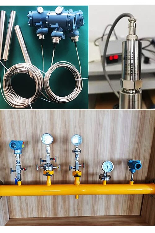
Fluid Pressure Sensor

What is a pressure sensor?

Typically, a pressure sensor (sometimes called a pressure transducer or pressure transmitter) is used to measure the pressure of a fluid (gas or liquid).
Pressure is an expression of the force required to stop a fluid from expanding, and is usually expressed in force per unit area.
Pressure sensors generate electrical signals related to the applied pressure. Such signals are usually digital or analog, but optical, visual and auditory signals are also common.
Industrial pressure sensors, also known as pressure transducers, pressure transmitters, pressure indicators and pressure switches.

Extended Reading: Smart pressure transmitter working principle

How do fluid pressure sensors work?

An instrument for measuring fluid pressure. Usually the measured pressure is compared to a reference pressure (such as atmospheric pressure or other given pressure), thus measuring the relative pressure or pressure difference.

According to the working principle, it can be divided into three types: liquid column, elastic and sensor.

The principle of the pressure sensor is to convert the pressure signal into an electrical signal. Such as strain type, elastic element deformation caused by resistance change. Piezoelectric, the use of piezoelectric effect.

Various pressure sensors can be miniaturized, more accurate and fast to measure, especially to measure dynamic pressure, realize multi-point inspection, signal conversion, long-distance transmission, computer connection, timely processing, etc., so as to develop rapidly and widely used.

Extended reading : Types of pressure sensors

Applications of fluid pressure sensors

Fluid pressure sensors are mainly used in: construction machinery, hydraulic and pneumatic systems, petrochemicals, energy and water treatment, water conservancy and hydropower, compressors and other fields:

In the hydraulic system, the pressure sensor is mainly used to complete the closed-loop control of the force. Extended reading: Hydraulic oil flow measurement solutions.

When the control spool moves suddenly, a peak pressure several times the working pressure of the system will be formed in a very short period of time.

In typical mobile and industrial hydraulics, any pressure sensor can quickly be destroyed if not designed with such extreme conditions in mind.

Shock-resistant pressure sensors are required. There are two main ways for pressure sensors to achieve shock resistance, one is a strain gauge chip, and the other is an external coil. Generally, the first method is used in hydraulic systems, mainly because Easy to install.

Another reason is that the pressure sensor is subject to constant pressure pulsations from the hydraulic pump.

Extended reading: extrusion melt pressure transducer

Fluid pressure sensors are often used in safety control systems, such as the safety management system of the air compressor itself.

In the field of security control, the application is generally considered from the performance aspect, as well as the safety and convenience of the actual operation.

The fluid pressure sensor can install some components and signal conditioners and other devices on a very small chip through materials and advanced processing technology. Therefore, its small size is also its advantage. Of course, it can also improve the accuracy of system testing to a certain extent. .

In the safety control system, the pressure brought by the compressor is controlled to a certain extent by installing a pressure sensor in the piping equipment of the air outlet. This is a certain protection measure and a very effective control system.

When the compressor starts normally, if the pressure value does not reach the upper limit, then the controller will open the air inlet and adjust the equipment to reach the maximum power.

Extended Reading: Resistive Pressure Transducer

Fluid pressure sensors play an important role in injection molds.

It is installed in the nozzle of the injection molding machine, the hot runner system, the cold runner system and the cavity of the mold to measure the distance between the nozzle of the injection molding machine and the cavity during the injection molding, filling, pressure holding and cooling of the plastic. plastic pressure.

Extended reading: High Pressure Hydraulic Flow Meter

There are many kinds of pressure sensors, for the special environment of mine pressure monitoring.

Mine pressure sensors mainly include: semiconductor piezoresistive pressure sensors, metal strain gauge pressure sensors, differential transformer pressure sensors, etc.

The above sensors are widely used in the mining industry, and the specific sensor to be used needs to be selected according to the specific mining environment.

Extended reading: High Pressure Flow Meters for Liquids-Steam-Gas

Pressure sensors are commonly used in air compressors, as well as air conditioning and refrigeration equipment. These sensor products are small in size and easy to install. In addition, the pressure guide port generally adopts a special valve needle design.

Extended reading: Pressure Sensor Applications In Various Industries

Read more about: Calculation Of Pressure Drop

Pressure Sensor For Liquid Level Measurement

In physics, the pressure P of a liquid is determined by the relationship: p=pgh.

For the same kind of liquid, the liquid density p is constant. Therefore, the pressure P of the liquid is linearly proportional to the height h of the liquid surface (the height from the liquid surface).

It is not difficult to find that the pressure of the liquid at different heights of the liquid level is also different.

As shown in the figure above, when the pressure sensor is used to measure the liquid level, the pressure sensor is installed at the bottom of the tank. When the liquid level in the tank changes, the height h from the tank bottom to the liquid level also changes at the same time, and the pressure naturally changes accordingly, thus achieving the purpose of continuous measurement.

One of the advantages of using pressure sensors for liquid level measurement is non-contact. Compared with mechanical and static methods, when measuring, it does not require too many parts to contact the liquid, and the installation is relatively convenient.

In addition, in terms of measurement principle, compared with similar non-contact measurement methods such as laser and ultrasonic, the relationship of pressure sensor measurement principle is simpler and linear, and it is more intuitive in data processing, analysis and processing.

Extended reading: Differential pressure level transmitter working principle

Pressure Sensors For Flow Measurement

The pressure of the fluid is an extremely important parameter in flow measurement. Differential pressure flowmeter uses the pressure difference at both ends of the throttling element to realize flow measurement.

In addition, the working pressure of the flowmeter can be known through pressure measurement, and necessary correction calculations are performed to ensure the accuracy of flow measurement.

Extended reading: flow rate and pressure relationship

Differential pressure flow meter advantages and disadvantages

Upstream and Downstream Flow Straight Pipe Requirements-for Flowmeter Installation

fluid depth pressure sensor

If we make the pressure sensor into a submersible sensor, it can be used to measure the depth of the liquid.

The most common fluid depth pressure sensor is what we often call the submersible hydrostatic pressure sensor. Used to measure the depth or level of liquids such as water, fuel.

Hydrostatic level measurement is often used for tank level measurement. Hydrostatic level measurement is one type of continuous level measurement.

Hydrostatic pressure sensors are used to measure the level or fill height of liquids. Hydrostatic pressure measurement is suitable for liquid level measurement due to the static pressure effect of non-flowing fluids. This physical principle describes the effect of the gravity of a stationary (i.e. non-flowing) liquid on the measurement point. This gravity is often described as “hydrostatic pressure”.

Related pressure transmitter

Related Pressure Measurement Solutions

What Is a Smart Pressure Transmitter?

What Is a Smart Pressure Transmitter? Smart pressure transmitter is also called Smart pressure sensor or Smart pressure transducer. Smart pressure transmitter is the best pressure measuring instrument. It is…

High Temperature Pressure Transducer with Best Price

High Temperature Pressure Transducer is also called High Temperature Pressure Sensor, or High Temperature Pressure Transmitter. The High Temperature Pressure Transducer is used for applications where the medium temperature exceeds…

Static Pressure/Hydrostatic Pressure Transmitter

The Hydrostatic Pressure Transmitter measures the hydrostatic pressure exerted by a hydrostatic head. Use these hydrostatic pressure transmitters to measure the liquid level in storage tanks, processing vessels, collection tanks,…

How to convert a 4-20mA to 0-10V /1-5V signal?

4-20mA to 0-10v voltage, this is I/V conversion. That is current-voltage conversion, usually used for long-distance signal transmission in the industry. How to convert a 4-20mA to 0-10V /1-5V signal?…

What is a pressure sensor?

What is a pressure sensor? A pressure sensor is a device that senses a pressure signal and converts the pressure signal into a usable output electrical signal according to certain…

What is a PID controller?

What is a PID controller? A PID controller is an instrument used in industrial control applications to regulate temperature, flow, pressure, speed, and other process variables. PID is the abbreviation…

What Is an Air Pressure Transducer?

An Air pressure transducer is a sensor that converts the mechanical signal of air pressure into a current signal. Pressure has a linear relationship with voltage or current, and it…

Introduction to Piezoelectric Pressure Sensors

What is a piezoelectric pressure sensor? The piezoelectric pressure sensor is a sensor that uses the piezoelectric effect of piezoelectric materials to convert the measured pressure into an electrical signal…

Cryogenic Pressure Transducers

Cryogenic pressure transducer for low temperature pressure measurement.  -196℃~+125℃、-260℃/-350c(especial). Sino-Inst offers a variety of Pressure Sensors for pressure measure and control. If you have any questions, please contact our sales…

High Frequency Dynamic Pressure Sensor

Dynamic pressure sensor, the transmitter is a high frequency sensor. Sino-Inst offers a variety of  Dynamic Pressure Sensors for pressure measurement. If you have any questions, please contact our sales…

Differential Pressure Transmitter Installation Guide

Differential pressure transmitter installation guide helps you solve the installation problem of DP Transmitters. Sino-Inst offers a variety of  differential pressure transmitters for pressure/level/flow measurement. If you have any questions,…

Differential Pressure Flow Meters

Differential Pressure Flow meters, also known as DP flow meters. Differential Pressure (DP) flow meters introduce a constriction in the pipe, that creates a pressure drop across the flow meter…

Water Pressure Transducers

Water pressure transducers also called a water pressure sensor, are pressure transmitters that can measure water pipe pressure. For the water level/water depth measurement, in the tank, or in the…

Pressure indicator transmitters

What is a pressure indicator transmitter? Pressure indicator transmitters are industrial instruments, which has a digital display for providing a local indication of pressure indicating,and a 4-20 mA output pressure transmitter…

Pressure Transmitter Calibration

Pressure transmitter calibration is what you need to do before you install the pressure transmitters. Also called pressure transducer calibration, or pressure sensor calibration. In this article, we will share…

How Does a Pressure Transmitter Work?

A pressure transmitter also often called a pressure transducer. A pressure transmitter is a device used to measure the pressure of liquids or gases in pipes or containers. It works…

Frequently
Asked
Questions

  1. Nonlinear error: This is a factor that has little effect on the initial error of the pressure sensor. The reason for the error is the physical nonlinearity of the silicon chip, but for sensors with amplifiers, the nonlinearity of the amplifier should also be included, the linearity error curve can be a concave or convex dynamometer.
  2. Offset error: Since the vertical offset of the pressure sensor remains constant over the entire pressure range, the diffusion variation of the converter and laser trim correction will generate offset errors.
  3. Sensitivity error: The magnitude of the error is proportional to the pressure, if the sensitivity of the device is higher than the typical value, the sensitivity error will be an increasing function of the pressure. If the sensitivity is lower than typical, then the sensitivity error will be a decreasing function of pressure. The cause of this error is a change in the diffusion process.
  4. Hysteresis error: In most cases, the hysteresis error of the pressure sensor can be completely ignored. Because the silicon chip has high mechanical stiffness. Typically, only hysteresis errors need to be considered when pressure changes are large.

Four errors of pressure sensors are inevitable. We can only choose high-precision production equipment. Using high technology to reduce these errors, it is also possible to perform error calibration at the factory and try to reduce errors as much as possible. Therefore, you don’t need to pay too much attention when using it, but try to reduce these errors as much as possible.

Extended Reading: MEMS Pressure Sensors

Please note that Pressure Transmitter Calibration is required after the pressure transmitter has been used for a period of time. In order to ensure the accuracy of the quantity.

pressure transducer often called a pressure transmitter, is a transducer that converts pressure into an analog electrical signal.

Although there are various types of pressure transducers, one of the most common is the strain-gage base transducer.

The conversion of pressure into an electrical signal, is achieved by the physical deformation of strain gauges, which are bonded into the diaphragm of the pressure transducer, and wired into a Wheatstone bridge configuration.

Pressure applied to the pressure transducer produces a deflection of the diaphragm, which introduces strain to the gages.

The strain will produce an electrical resistance change proportional to the pressure.

Extended reading: Pressure transmitter working principle

Of course, you can install a pressure gauge.

Pressure transmitters can be categorized into four main types:

  • Gauge Pressure Transmitter.
  • Absolute Transmitters.
  • Differential-Pressure Transmitter.
  • Multivariable Pressure Transmitters.

Extended reading: High accuracy pressure transducers

Flow is an important parameter in industrial production and life. The amount of fluid flowing through a section of a pipe per unit time is called instantaneous flow. Instantaneous flow is divided into volume flow and mass flow. A flow sensor is a sensor that measures the flow of a fluid. Flow sensor is an important instrument in measurement technology, it is widely used in industrial process control, life science and technology, commercial application, military and other fields. In recent years, with the development of science and technology and the development of human needs, flow sensors are also constantly developing.

Extended reading: Digital Flow Meters

In the hydraulic system, the closed-loop control of the force is mainly caused by the pressure sensor.
The working principle of the pressure sensor in the hydraulic system is that the pressure acts directly on the diaphragm of the sensor. Make the diaphragm produce micro-displacement proportional to the medium pressure. Causes the resistance of the sensor to change. And by using an electronic circuit to detect the change, a standard signal corresponding to the pressure is converted and output.

Sino-Inst offers over 50 pressure sensors for fluid measurement. About 50% of these are differential pressure flow meters, 40% is the liquid pressure sensor, and 20% are pressure Level Transmitter.

A wide variety of Fluid Pressure Sensors options are available to you, such as free samples, paid samples.

Sino-Instrument is a globally recognized supplier and manufacturer of pressure measurement instrumentation, located in China.

Request a Quote

Please enable JavaScript in your browser to submit the form

Influence of Dielectric Constant on Liquid Level Measurement | Radar-Guided Wave Radar Level Meter

“Low dielectric constant liquid measurement, not suitable for radar level gauge”. Inadvertently, we hear this all the time. In fact, when I first entered the industry, I thought so too. After a long time and understanding more, I realized that this statement is a bit one-sided. Let’s discuss it in detail.

what is dielectric constant?

The dielectric constant is the main parameter reflecting the dielectric properties or polarization properties of the piezoelectric smart material dielectric under the action of an electrostatic field. Usually denoted by ε.
Different applications of piezoelectric elements have different requirements for the dielectric constant of piezoelectric smart materials.
When the shape and size of the piezoelectric smart material are certain. The dielectric constant ε is determined by measuring the intrinsic capacitance CP of the piezoelectric smart material.

Commonly used dielectric constant table

gastemperature(℃)Relative dielectric constantliquidtemperature(℃)Relative dielectric constant
water vapor140~1501.00785solid ammonia-904.01
gaseous bromine1801.0128solid acetic acid24.1
helium01paraffin-52.0~2.1
hydrogen01.00026polystyrene2024~2.6
oxygen01.00051wireless porcelain166~6.5
nitrogen01.00058UHF porcelain7~8.5
Argon01.00056barium dioxide106
gaseous mercury4001.00074rubber2~3
Air01hard rubber4.3
hydrogen sulfide01.004Paper2.5
vacuum201dry sand2.5
ether04.33515% water wet sand约9
liquid carbon dioxide201.585wood2~8
methanol2033.7amber2.8
Ethanol16.325.7ice2.8
water vapor1481.5shellac3~4
liquid ammonia-270.816.2Celluloid3.3
liquid helium-2531.058Glass4~11
liquid hydrogen-1821.22Yellow phosphorus4.1
liquid oxygen-1851.465sulfur4.2
liquid nitrogen02.28carbon (diamond)5.5`16.5
liquid chlorine201.9Mica6~8
kerosene202~4granite7~9
turpentine2.2marble8.3
benzene2.283salt6.2
paint3.5Beryllium oxide7.5
glycerin45.8

Dielectric constants of common liquids

The relative permittivity of common solvents is at room temperature and the test frequency is 1KHz.

  • H2O (water) 78.5
  • HCOOH (formic acid) 58.5
  • HCON (CH3) 2 (N,N-dimethylformamide) 36.7
  • CH3OH (methanol) 32.7
  • C2H5OH (ethanol) 24.5
  • CH3COCH3 (acetone) 20.7
  • n-C6H13OH (n-hexanol) 13.3
  • CH3COOH (acetic acid or acetic acid) 6.15
  • C6H6 (benzene) 2.28
  • CCl4 (carbon tetrachloride) 2.24
  • n-C6H14 (n-hexane) 1.88
  • n-C4H10 (No. 4 solvent) 1.78

Extended reading: Non contact level measurement

Influence of Dielectric Constant on Guided Wave Radar Level Meter

From the point of view of process conditions, the dielectric constant of the medium to be measured plays a very important role in the measurement of guided wave radar as a known condition.

According to the electrical properties of the dielectric constant, it is roughly divided into three categories: non-polar substances (εr<2.8), weakly polar substances (2.8≤εr≤3.6), polar substances (εr>3.6) .

For liquefied petroleum gas, petroleum, gasoline or other hydrocarbons in petrochemical plants, and petrochemical products, 1.4≤εr≤4.0.
Alcohol, organic solvent, oil-water mixture, etc., 4.0≤εr≤10.0.
Conductive liquids, such as water-based solutions, dilute acids and bases, εr>10.0.

The Guided Wave Radar Level Meter can measure gas/liquid, gas/solid, and liquid/liquid two-phase interfaces.

Ideal for measuring liquid/liquid interfaces, such as oil-water interfaces.

Extended reading: Oil-water interface measurement-Magtech magnetic level indicator

The Guided Wave Radar Level Meter emits low-energy pulsed microwaves that are sent down the probe at the speed of light. At the interface between the probe and the medium, a considerable proportion of microwave energy is reflected back to the transmitter through the probe to receive the first echo signal.

A certain percentage of the pulses will continue down the probe, traversing the upper low dielectric constant medium until it is reflected on the lower medium surface and the transmitter receives the second echo.

To measure the boundary, the minimum thickness of the upper medium is 10-20 cm, so that the echoes of the two liquids can be distinguished. The maximum thickness of the upper dielectric depends on its dielectric constant.

The dielectric constant of the liquid in the upper layer is relatively low, and the difference between the dielectric constants of the upper layer and the lower layer liquid is required to be greater than 10, and the upper layer medium εr<3, the lower layer medium εr>20. Only in this way can the obvious reflection effect be obtained. Both level and interface can be measured simultaneously.

The smaller the dielectric constant of the medium, the greater the amplitude of the reflected signal. For the medium with low dielectric constant (1.2≤εr≤2.5), the guided wave radar level gauge can be selected for powdery or volatile medium.

Some substances hinder or absorb electromagnetic waves in the gas phase, and there are substances in the gas phase that weaken electromagnetic waves. For example, dust, powder (graphite, iron alloy, etc.) with high conductivity, or volatile media. For example, the dielectric constant of liquid ammonia is at room temperature 25 ℃. It is 14.9, which is a conductive medium and can be measured effectively.

The advanced Guided Wave Radar Level Meter is especially suitable for measuring a variety of powders. And liquids with inclined liquid levels caused by vortices.

Because the reflected wave does not depend on a “flat” surface to reflect the echo, microwave safe transmission makes the medium surface condition less affected. Disturbed liquid surface or foam formation, as well as different curved surfaces or furnace outlet will not affect the measurement. Therefore the Guided Wave Radar Level Meter also has a good measurement effect in turbulent situations.

From the perspective of measurement range, the medium with higher dielectric constant has better reflection performance and is suitable for longer measurement range. Guided Wave Radar Level Meter adopts two-wire loop power supply, 24V (DC) or 220V (AC) liquid level transmitter, low energy consumption, and meets the control level process requirements.

Extended Reading: Low Cost Float Level Sensor for Tank Liquid Volume Monitoring

Influence of Dielectric Constant on Radar Level Meter

The Radar Level Meter adopts the principle of transmit-reflection-receive. The antenna of the Radar Level Meter emits electromagnetic waves. These electromagnetic waves are reflected by the surface of the measured object and then received by the antenna. The time from emission to reception of electromagnetic waves is proportional to the distance to the liquid surface.

In the measurement of Radar Level Meter, the measured medium needs to provide sufficient radar reflection signal. In general, the higher the dielectric constant, the stronger the reflected signal. The farther away the target is, the greater the intensity of the reflection is required. In order to have sufficient signal back to the radar transmitter.

When the radar wave reaches the liquid level surface and is reflected. The radar wave will be absorbed and attenuated. When the attenuation is too much, the radar level gauge will not receive enough signal, resulting in inaccurate measurement. This is the dielectric constant of the measured medium. Effects of radar level gauge measurements.

From this point of view, the dielectric constant has an effect on the Radar Level Meter measurement. However, this problem has been well resolved.

The Radar Level Meter can also perform interface measurements, especially on oil-water interfaces.

Principle: When measuring the interface, the part of the pulse that is not reflected on the surface of the upper product will continue down to the surface of the lower product, and then be reflected back.

The requirements for the dielectric constant when the Radar Level Meter measures the interface are as follows:

(1) The dielectric constant of the upper product must be known and must not be changed;
(2) The difference between the dielectric constants of the two products must be greater than 6;
(3) Mainly used in the interface between oil-water liquid and water/water-like liquid with lower dielectric constant of the upper layer (<3) and higher dielectric constant of the lower product (>20).

Extended Reading: What is level transmitter working principle?

Frequently
Asked
Questions

Water is extremely unique in that it has a high dielectric constant (=80). A high dielectric constant suggests that the solvent (in this case, water) has the ability to screen charges. This means that water molecules will surround both anions and cations in a solution, and ultimately, diminish the attraction of the two charges. 

Perhaps a Coaxial Probe Guided Wave Radar Level Transmitter can work for your low dielectric constant.

For example, if you place a cation (such as sodium) in water, the positive charge (+) of sodium is able to interact with anions and other molecules. However, because water has such a high dielectric constant, there is a decreasing effect on the interaction between sodium and its counter-ion. This is primarily because the charges interact with the electric dipole of water more than with each other, decreasing the overall interaction. In comparison to water, the interaction between anions and cations is much greater when placed in solvents with lower dielectric constants

Quote from: Wikibooks Structural Biochemistry/Unique Properties/High Dielectric Constant

The dielectric constant of polar liquid dielectrics decreases with increasing voltage frequency. This is because the carrier mobility is enhanced, making it easier to conduct electricity. such as electrolytic capacitors.

Although radar level meters are affected by the dielectric constant of the medium. Ultrasonic level meters are not affected. More about Ultrasonic Level Sensor Applications.

So far there is no sensor that can measure the volume of liquid. Because there are various shapes of liquid containers, such as cylinders, spheres, rectangles, cylinders and squares with hemispherical ends.

The height of the liquid in these containers can be detected by a variety of sensors. According to the shape of the container, the volume and weight of the liquid in the container can be calculated.

For rectangles, cylinders or squares, the volume and weight of the liquid can be calculated directly by multiplying the floor area of the container by the height of the liquid. And the corresponding relationship is linear. The hemispherical cylinder and sphere at both ends can be calculated by definite integral. The law of curvature change is the volume formula of the function. Calculate the volume and weight of the liquid according to the height of the liquid.

Read more about: Monitoring liquid volume solutions

Radar level instruments measure the distance from the transmitter (located at some high point) to the surface of a process material located farther below in much the same way as ultrasonic transmitters – by measuring the time-of-flight of a traveling wave.

Read more about: Ultrasonic VS Radar level transmitter-different applications

A guided wave radar level transmitter is also called a wave-guided radar level sensor. They can measure both levels and the interface between two media. Through probe rod or cable, complete level contact types continuous level measurement. Such as Coaxial Probe Guided Wave Radar Level Transmitter. This is different from ultrasonic level measurement, which is a non-contact measurement. A guided wave radar level transmitter is often used for tank level measurement. Including liquid and solid. Output 4~20mA/HART, so as to measure and control the level during production.

Extended Reading: Guided-wave radar (GWR) level transmitter working principle

Related Level Sensors

Related Level Measurement Solutions

Water Level Transducers – Detailed Guide

Posted on
What Is a Water Level Transducer? Water level transducers are also called Water Level Sensors, or water level transmitters. Water level transducers are used to monitor water usage and quality…

External Tank Level Indicator

Posted on
External Mounted Tank Level Sensors External Tank Level Indicator refers to an externally mounted level sensor. It is used to install on the outside of the liquid storage tank to…

Material Level Indicators

Posted on
The material level indicator refers to an instrument for real-time detection of changes in the height of solid materials in a container. Material level indicator is also known as material…

80GHZ Radar Level Transmitter

Posted on
80 GHz Radar Level Measurement 80GHZ Radar Level Transmitter refers to a frequency modulated continuous wave (FMCW) radar product operating at 76-81GHz. It can be used for level measurement of…

Choose the Right Float Switch for Water Tank

Posted on
Float Switch for Water Tank is a switch that can adjust the liquid level status of water tanks, buckets, pools and other fields. It can also be used to control…

Tank Level Gauges & Indicators

Posted on
Tank level gauges are instruments used to indicate and control the height of the liquid level in the tank. Commonly used in water storage tanks, oil storage tanks, and underground…

Ultrasonic level transmitter VS Radar level transmitter

Posted on
Radar level transmitter and Ultrasonic level transmitter are both liquid level measuring instruments. The most obvious difference is that one uses electromagnetic waves and the other uses ultrasonic waves. So,…

Point Level Measurement Sensors

Posted on
What is Point Level Measurement? Point Level Measurement refers to the use of a point level sensor to detect the material level in a storage tank or silo. Also called…

Powder Silo/Bin Level Measurement and Control System

Posted on
The Silo/Bin level measurement and control system solves the problem of frequent dumping accidents in the powder silo of the mixing station during the feeding process. It avoids the problems…

Sino-Inst offers over 50 level sensors for level measurement. About 30% of these are Radar level meters, 30% of these are guided wave radar level sensor, 40% is other tank level sensors.

A wide variety of liquid level meters options are available to you, such as free samples, paid samples.

Sino-Inst is a globally recognized supplier and manufacturer of liquid level measurement instrumentation, located in China.

Request a Quote

Please enable JavaScript in your browser to submit the form

Liquid Volume Sensor? Monitors Liquid Volume Solutions

Ideally, we should be able to use a liquid volume sensor to directly measure the volume of the liquid in the container. Well, but in fact, there is no mature liquid volume sensor product on the market.

Because there are various shapes of liquid containers. Such as cylinders, spheres, rectangles, cylinders and squares with hemispherical ends.

So why are we talking about liquid volume sensor here? Don’t worry, we don’t have a mature liquid volume sensor. However, we have A dozen ways for liquid level measurement, with different level sensors. Combined with Sino-Inst’s volume recorder. It can collect, display and convert the liquid level of various regular and irregular tanks in the industrial field into the corresponding tank volume. It is suitable for monitoring, controlling and collecting various process parameters.

Featured Level Sensors

Level Measurement Technologies

Principle: The principle of the connector. Developed according to the principle of buoyancy and magnetic coupling.

When the liquid level in the container under test rises and falls. The permanent magnet steel in the float is transmitted to the magnetic flip column indicating panel through magnetic coupling. Flip the red and white columns over 180°.

The column turns from white to red when the liquid level rises.
The column turns from red to white when the liquid level drops.

The junction of red and white on the panel is the actual height of the liquid level in the container, so as to realize the liquid level display.

The structure of the float level meter is mainly designed and produced based on the principles of buoyancy and static magnetic field.

The position of the float with a magnet (abbreviated as float) in the measured medium is affected by buoyancy: changes in the liquid level lead to changes in the position of the magnetic float.

The magnet and sensor (reed switch) in the floating ball act to change the number of components (such as fixed-value resistors) connected in series to the circuit, thereby changing the electrical quantity of the instrument circuit system.

That is, the change of the position of the magnetic float causes the change of the electrical quantity.

The liquid level in the container is reflected by detecting the change of the electrical quantity.

It is designed and manufactured using the principle of mechanical balance.

When the liquid level changes, the original mechanical balance will reach a new balance through the movement of the steel belt under the disturbance of the buoyancy of the float.

The liquid level detection device (float) drives the steel belt to move according to the liquid level. The displacement transmission system drives the transmission pin to rotate through the movement of the steel belt. It then acts on the counter to display the liquid level.

The radar level meter is a measuring instrument based on the principle of time travel. The radar wave runs at the speed of light, and the running time can be converted into a level signal by electronic components.

The probe emits high-frequency pulses and propagates along the cable probe. When the pulses meet the surface of the material, they are reflected back and received by the receiver in the instrument. The distance signal is converted into a level signal.

When the sensor of the magnetostrictive level transmitter works, the circuit part of the sensor will excite a pulse current on the waveguide wire. When the current propagates along the waveguide wire, a pulse current magnetic field will be generated around the waveguide wire.

There is a float outside the sensor rod of the magnetostrictive liquid level gauge. This float can move up and down along the rod with the change of the liquid level.

Inside the float there is a set of permanent magnetic rings.

When the magnetic field of the pulse current meets the magnetic field of the magnetic ring generated by the float, the magnetic field around the float changes so that the waveguide wire made of magnetostrictive material generates a torsional wave pulse at the position of the float. The waveguide wire is returned and detected by the detection mechanism.

By measuring the time difference between the pulse current and the torsional wave, the position of the float, that is, the position of the liquid surface, can be accurately determined.

The radio frequency admittance level meter is composed of a sensor and a control instrument. The sensor can be installed on the roof of the warehouse using rod-type, coaxial or cable-type probes.

The pulse card in the sensor can convert the material level change into a pulse signal and send it to the control instrument. After the control instrument is processed and converted into engineering quantity and displayed, it realizes the continuous measurement of the material level.

The working principle of the tuning fork level controller is to make the tuning fork vibrate at a certain resonance frequency through a pair of piezoelectric crystals installed on the tuning fork base.

When the tuning fork is in contact with the measured medium, the frequency and amplitude of the tuning fork will change. These changes are detected, processed and converted into a switching signal by an intelligent circuit.

The glass plate type liquid level meter is connected to the container through the flange to form a communication device, and the height of the liquid level in the container can be directly read through the glass plate.

The pressure level transmitter adopts the principle of static pressure measurement.

When the liquid level transmitter is put into a certain depth in the measured liquid.

At the same time as the pressure on the liquid surface of the sensor, the pressure of the liquid is introduced into the positive pressure chamber of the sensor through the air-conducting stainless steel. Then the atmospheric pressure Po on the liquid surface is connected to the negative pressure chamber of the sensor to offset the Po on the back of the sensor.

The pressure measured by the sensor is: ρ .g.H , and the liquid level depth can be obtained by measuring the pressure P .

Capacitive level meters measure the level of liquid level by measuring changes in capacitance.

It is a metal rod inserted into the liquid container. The metal rod is used as one pole of the capacitor. The wall of the container is used as the other pole of the capacitor.

The medium between the two electrodes is the liquid and the gas above it.

Because the dielectric constant ε1 of the liquid and the dielectric constant ε2 on the liquid surface are different. For example: ε1>ε2.

Then when the liquid level rises, the total dielectric constant value between the two electrodes of the capacitive liquid level gauge increases accordingly and the capacitance increases.

Conversely, when the liquid level drops, the value of ε decreases, and the capacitance also decreases.

Therefore, the capacitive liquid level meter can measure the level of the liquid level through the change of the capacitance between the two electrodes.

The intelligent electric displacer liquid level meter is a liquid level measuring instrument designed according to Archimedes’ law and the principle of magnetic coupling. The instrument can be used to measure the liquid level, boundary level and density, and is responsible for the output of upper and lower limit alarm signals.

It is designed and manufactured using the principle of mechanical balance.

When the liquid level changes, the original mechanical balance will be disturbed by the buoyancy of the float. The new balance will be achieved by the movement of the steel belt (rope).

The liquid level detection device (float) drives the steel belt (rope) to move according to the liquid level. The displacement transmission system drives the on-site indicating device through the movement of the steel belt (rope), and then displays the liquid level on the display device.

The pontoon is submerged in the liquid in the pontoon chamber and is rigidly connected to the torsion tube system. The force on the torsion tube system is the net weight of the pontoon minus the buoyancy on the pontoon. Under the action of this combined force, the torsion tube is twisted by a certain angle.

Changes in the position, density or boundary level of the liquid in the buoyancy chamber cause the buoyancy force of the buoyancy immersed in the liquid to change, so that the twisting angle of the tube also changes.

This change is transmitted to a sensor rigidly connected to the torsion tube. Change the sensor output voltage. Then it is amplified by electronic components and converted into 4-20mA current output.

Displacer level transmitters use microcontrollers and associated electronics to measure process variables. Provides current output. Drive LCD display and provide HART communication capability.

The magnetic-sensitive electronic two-color liquid level meter is made of high-quality stainless steel and imported electronic components.

The display part adopts high-brightness LED two-color light-emitting tube to form a columnar display screen.

Through the red and green changes of the LED light column, the upper and lower limit alarm and control of the liquid level can be realized.

The external liquid level meter is an instrument that measures the liquid level from the outside of the container using the principle of sonar ranging and “micro-vibration analysis” technology.

Two small external level gauge ultrasonic sensors are installed on the bottom of the tank and the other on the side wall of the tank to compensate for density changes.

The signal of the external level meter sensor is converted by the microprocessor and output to the local display or user control system. Can calculate the height of the liquid in the tank and the volume of the liquid in the tank

The hydrostatic level transmitter encapsulates the diffused silicon oil-filled core in a stainless steel shell.

The front protective cap protects the sensor diaphragm. It can also make the liquid contact the diaphragm smoothly. The water wire is sealed with the housing. The ventilation tube is connected to the outside world in the cable. The internal structure is designed to prevent condensation.

Ultrasonic level Sensor is composed of a complete ultrasonic sensor and control circuit.

The ultrasonic wave emitted by the ultrasonic sensor is reflected by the liquid surface. The time required to return is used for calculation.

The temperature influence in the ultrasonic transmission process is corrected by the temperature sensor, which is converted into the distance between the liquid surface and the ultrasonic sensor.

Output 4mA-20mADC analog signal through LCD screen. Realize remote reading of field instruments.

The differential pressure liquid level transmitter is an electrical component that measures the high and low pressure difference, and then converts it into a current signal by the conversion component and transmits it to the control room.

Differential pressure liquid level transmitter is mainly used for liquid level measurement of closed pressure vessels.

The size of the differential pressure also represents the size of the liquid level height.

Use a differential pressure gauge to measure the differential pressure between the gas and liquid phases to know the liquid level.

Liquid Volume Sensor

So far there is no sensor that can measure the volume of liquid. Because there are various shapes of liquid containers, such as cylinders, spheres, rectangles, cylinders and squares with hemispherical ends.

The height of the liquid in these containers can be detected by a variety of sensors. According to the shape of the container, the volume and weight of the liquid in the container can be calculated.

For rectangles, cylinders or squares, the volume and weight of the liquid can be calculated directly by multiplying the floor area of the container by the height of the liquid. And the corresponding relationship is linear. The hemispherical cylinder and sphere at both ends can be calculated by definite integral. The law of curvature change is the volume formula of the function. Calculate the volume and weight of the liquid according to the height of the liquid.

Monitoring liquid volume solutions

Most of our liquid level sensors can output liquid level signals, such as 4-20mA signal, 0-10V signal, RS485 and so on.

However, the liquid level transmitter alone cannot calculate the liquid volume of tanks of different sizes. It’s too complicated. A separate recorder is required to calculate it.

Therefore, the digital display volume meter can collect, display and convert the liquid level of various regular and irregular tanks in the industrial field into the corresponding tank volume. It is suitable for monitoring, controlling and collecting various process parameters.

So, How to measure volume of liquid?

After the liquid level gauge is installed in your tank, Sino-Inst’s volume display controller/recorder can collect, display and convert the liquid level of various regular and irregular tanks on the industrial site into the volume of the corresponding tank . It is suitable for monitoring, controlling and collecting various process parameters.

The volume meter is equipped with volume download software as standard. Form a liquid level volume comparison table. Import volume meter, suitable for volume conversion of various regular or irregular tanks.

The meter is equipped with RS232 communication interface as standard. Connect with the host computer. Through the volume download software, data writing for regular and irregular tanks can be realized. 1000 sets of data can be downloaded.

Volume Recorder

LCD Volume Display Regulator/ Recorder is specifically designed for industrial on-site regular and irregular canned liquid, volume and mass conversion.

It is based on a 32-bit ARM micro-processor and equipped with the secondary meter with high-speed AD and high-capacity storage unit.

The device has empowered by the surface mounting technology, featuring the design of multiple-layered protection and isolation, with a strong anti-interference capability and high reliability.

It has used the embedded operating system with USB data dump function.

The data storage time could reach up to 720 days.

By using U disk and host computer analysis software, one could call and view the historic curve of process variants and relevant historic data from time to time.

It also could match with various liquid sensors, such as ultrasonic liquid level meter. The device has sound anti-theft and anti-damage and other features.

Measurement Input
Input Signal Current: 0~20mA, 0~10mA, 4~20mA, 0~10mA rooting, 4~20mA rooting
Input impedance: ≤ 100Ω
Maximum input current limit: ≤ 30mA
Voltage: 0~5V, 1~5V, 0~10V (customized), 0~5V rooting, 1~5V rooting,
Input impedance: ≥ 500KΩ
Output
Output Signal Analog output: 4~20mA (load resistance ≤ 480Ω), 0~20mA (load resistance ≤ 480Ω), 0~10mA (load resistance ≤ 960Ω), 1~5V (load resistance ≥ 250KΩ), 0~5V (load resistance ≥250KΩ), 0~10 V (load resistance ≥4KΩ) (customized)
Alarm output: relay control output – AC220V/2A, DC24V/2A (resistive load)
Feed output: DC24V±1, load current ≤ 50mA
Communication output: RS485/RS232 communication interface, configurable baud rate of 1200~9600bps, standard MODBUS RTU communication protocol, RS-485 communication distance of up to 1km, and RS-232 communication distance of up to 15m.
General Parameters
Measuring Accuracy 0.2%FS±1d
Setting Mode Touch-panel-based key setting; password locking of parameter settings; permanent preservation of settings upon power failure.
Display Backlit 3.5-inch 128*64 high-resolution dot-matrix FSTN LCD
Support the display of Chinese characters, figures, curves and bar graphs, as well as screen page turning, historical data search and timescale changes of curves etc. through the panel keys
Recording Interval 1, 2, 4, 6, 15, 30, 60, 120, or 240 seconds, nine options available
Storage Length 3 days (with 1-sec interval) – 720 days (with 240-sec interval)
Printing Control RS-232C printer interface, supporting SP-A40SH series serial printers
Operating Environment Ambient temperature: 0~50; relative humidity: ≤ 85%RH; avoid strongly corrosive gas
Working Power Supply AC 100~240V (switching power supply), 50/60HZ; DC 20~29V (switching power supply)
Power ≤5W
Structure -Standard snap-in type

Frequently
Asked
Questions

Different types of liquid level sensors work based on different principles.

For example, a commonly used water level sensor:
Liquid level sensor (hydrostatic level gauge/liquid level transmitter/liquid level sensor/water level sensor) is a pressure sensor that measures liquid level. The hydrostatic submersion type liquid level transmitter (liquid level gauge) is based on the principle that the static pressure of the measured liquid is proportional to the height of the liquid. The isolated diffused silicon sensitive element or ceramic capacitive pressure sensitive sensor is used. Convert static pressure to electrical signal. After temperature compensation and linear correction, it is converted into a standard electrical signal (usually 4~20mA/1~5VDC).

Liquid level sensor (hydrostatic level gauge/liquid level transmitter/liquid level sensor/water level sensor) is a pressure sensor that measures liquid level.

The static pressure input liquid level transmitter (liquid level gauge) is based on the principle that the static pressure of the measured liquid is proportional to the height of the liquid. It adopts an isolated diffusion silicon sensitive element or a ceramic capacitive pressure sensitive sensor. The static pressure is converted into Electrical signal. After temperature compensation and linear correction, it is converted into a standard electrical signal (usually 4~20mA/1~5VDC).

It is suitable for liquid level measurement of various media in petrochemical, metallurgy, electric power, pharmaceutical, water supply and drainage, environmental protection and other systems and industries.

There are two ways to measure the volume of a liquid:

  1. The measuring cylinder can directly measure the liquid volume;
  2. Using the density formula, the volume of a liquid can be obtained as the quotient of the mass and density of the liquid.

Yes.
Ultrasonic sensors are widely used in liquid level detection. That’s the ultrasonic level sensor.

Liquid volume calculation formula: v=m/ρ, where m is mass, v is volume, and ρ is density.

Liquid volume formula: vml×cmol/l=n1.

Liquid is one of the three major forms of matter. It has no definite shape and is often influenced by the container. But its volume is fixed under the environment of constant pressure and temperature.

The distance between the molecules of the liquid is farther, the molecular motion is also more intense, and the attraction between the molecules is small. Increasing the temperature or reducing the pressure can generally vaporize the liquid and turn it into a gas.

Related liquid level monitoring solutions

Water Level Transducers – Detailed Guide

What Is a Water Level Transducer? Water level transducers are also called Water Level Sensors, or water level transmitters. Water level transducers are used to monitor water usage and quality…

External Tank Level Indicator

External Mounted Tank Level Sensors External Tank Level Indicator refers to an externally mounted level sensor. It is used to install on the outside of the liquid storage tank to…

80GHZ Radar Level Transmitter

80 GHz Radar Level Measurement 80GHZ Radar Level Transmitter refers to a frequency modulated continuous wave (FMCW) radar product operating at 76-81GHz. It can be used for level measurement of…

The Secret of Water Level Control

Water level control refers to the control of high and low water levels by mechanical or electronic methods. It can control solenoid valves, water pumps, etc. to become an automatic…

Tank Level Gauges & Indicators

Tank level gauges are instruments used to indicate and control the height of the liquid level in the tank. Commonly used in water storage tanks, oil storage tanks, and underground…

Oil-water Interface Level Measurement Guide

Interface level measurement is very important for oil and gas, chemical tanks. At the same time, Interface level measurement is also a measurement and control challenge. In today’s increasingly modernized…

CO2 Cylinder | Portable Liquid Level Gauge

Liquid Level Gauge also called Liquid level indicator. Liquid Level Gauge has contact and non-contact type. Here mainly discusses the non-contact Liquid Level Gauge, which is used for CO2 cylinder…

Procurement Guide: Ultrasonic liquid level sensors

Ultrasonic liquid level sensors realize the non-contact continuous detection of liquid level. Hope you can purchase Ultrasonic liquid level sensors at the best price after reading this Procurement Guide. Featured…

External Ultrasonic Tank Level Sensor

The external ultrasonic tank level sensors is the first choice for measuring liquid level and material level on various industrial tanks. Sino-Inst offers a variety of  ultrasonic level meters for…

7 Type Tank Level Senors For Liquid and Solid

Featured Tanks Level Sensors Tank Level Sensors Types: Extended reading: Diesel fuel tank level gauges & indicators After understanding these 7 types of Tank Level Senors, if you are experienced,…

Sino-Inst offers over 10 level transmitters for Liquid level measurement.

About 50% of these are liquid level meters, 40% is the tank level sensor.

A wide variety of level meters options are available to you, such as free samples, paid samples.

Sino-Instrument is a globally recognized supplier and manufacturer of level measurement instrumentation, located in China.

Request a Quote

Please enable JavaScript in your browser to submit the form

LORA Water Meter

LORA Water Meter is a commonly used wireless water meter/wireless flowmeter.

The wireless remote water meter measures the water flow in the pipeline. The microcomputer in the water meter automatically stores the amount of water used. When the time to send data regularly or when a meter reading signal is detected, the data is sent out through the wireless frequency band. Such as narrowband Internet of Things NB-IOT technology, LORA technology, GRS technology, etc.

There will be no signal interference, instead of manual meter reading. It is more convenient and faster, and the success rate of meter reading is high.

Featured Water Meters for Sale

What is LORA Smart Water Meter?

With the development of the Internet of Things technology, the “members” of the water meter family have undergone various changes. The new LORA smart water meter is favored by large water companies with spread spectrum modulation technology.

Presumably everyone is very unfamiliar with the word “LORA” in the Lora smart water meter. “LORA” stands for long-distance low-power data transmission, and it is a patented technology of a company in the United States. It uses chirp spread spectrum modulation technology and requires no wiring. A SIM card is added inside the concentrator host to realize wireless remote data transmission. Its receiving sensitivity has reached an astonishing -148dbm.

Compared with other advanced level chips in the industry. The higher receiving sensitivity improves more than 20db, which ensures the reliability of network connection.

Compared with other ordinary smart water meters, LORA smart water meters have the advantages of strong anti-interference, strong signal reception, low power consumption, and no wiring. Completely beats other ordinary smart water meters. It must be the trend of water meter products in the future.

Extended reading: Ultrasonic Water Meter Working Principle

Wireless Remote LORA Water Meter vs Mechanical Water Meter

With the continuous update of intelligent remote transmission technology, traditional mechanical water meters have been hit unprecedentedly in the industry. Will mechanical water meters be replaced by new smart water meters? Then we have to see which of their respective performance can better meet the market demand.

Let’s take the current popular LORA wireless remote water meter as an example to compare it with ordinary mechanical water meters.

The most prominent drawback of ordinary mechanical water meters is its meter reading method, and the impact of this drawback is becoming increasingly prominent.

In our inherent thinking, it is a very common and normal thing for meter readers to go door-to-door to read meters. However, under the impact of technologies such as the Internet of Things, the efficiency of door-to-door meter reading has been questioned.

The LORA wireless remote water meter developed using new technology is a meter reading command issued by the meter reader through the remote meter reading system. After the LORA module on the wireless remote water meter receives the meter reading command, it will The data is uploaded to the server. The meter reader can read the water meter data. This avoids the high cost and low efficiency of manual meter reading and the nuisance problems caused by household meter reading.

No matter what kind of water meter and what kind of function it has, they are all born to serve people’s lives. Whoever can provide more convenience and higher efficiency will be pushed to the stage of history.

Read more about: Choose the most suitable Inline flow meter

LoRa technology realizes the application of water meter-flow meter wireless transmission

LoRa is one of the LPWAN communication technologies, and it is an ultra-long-distance wireless transmission scheme based on spread spectrum technology adopted and promoted by Semtech in the United States. This solution changes the way of considering the compromise between transmission distance and power consumption in the past. Provide users with a simple system that can achieve long distance, long battery life, and large capacity, thereby expanding sensor networks.

At present, LoRa mainly operates in free frequency bands around the world, including 433, 470, 868, 915MHz, etc.

Extended reading: How to Select the Right Agriculture Flow Meter

LORA wireless RF module

Narrowband spread spectrum wireless communication module based on LORA technology.

Sino-Inst’s modular design idea, the battery and circuit are installed independently. It can be added or repaired later. It does not destroy the reliability of measurement.

One master and one slave connect two modules. There is no wiring trouble on site!

More Water Flow Solutions

Clamp on Water Flow Meter

What is Clamp on Water Flow Meter? Clamp on Water Flow Meter is also known as the clamp-on ultrasonic flowmeter. Using an ultrasonic flowmeter to measure water flow rate is…

Irrigation Flow Meters for Agriculture Water System

What is an irrigation flow meter? The irrigation flow meter is a flow meter designed for agricultural irrigation water counting. Agriculture, horticulture, etc. require water for irrigation. And water is…

Chilled Water Flow Meter

Application What is a Chilled Water Flow Meter? A chilled water flow meter refers to a flow meter that can be used to measure low-temperature water. Common chilled water flow…

Mechanical Water Flow Meters

Mechanical water flow meters refer to a type of flow meter suitable for clean water processes or applications. The working principle of a mechanical water flow meter is to measure…

BTU Meter for Chilled Water

What is BTU Meter for Chilled Water? The BTU Meter for Chilled Water accurately measures the thermal energy consumed by chilled water in British Thermal Units (BTU). This is a…

Inline water flow meters

Featured inline water flow meters Strap on flow meter X3  External clamp-on flow sensor. Easy to install. Suitable for measuring pipe diameter Φ9.53~Φ90. Ultrasonic Water Meter for Residential Water DN15-DN40,…

2 inch Water Flow Meter

2 inch water flow meter is also written as 2″ flow meter. If you are planning to buy a 2 inch water flow meter, please be sure to read this…

Mechanical Oil Flow Meters

What is mechanical oil flow meter? Mechanical oil flow meter refers to a flowmeter that can detect the volume flow of oil inline. Most importantly, this type of flowmeter is…

Kerosene Gasoline/ Kerosene Flow Meter

A kerosene flow meter is a flow meter that can be used to measure the flow of kerosene. Kerosene is a common oil in industrial production. It is an organic…

Slurry Flow Meter

Flow Meter for Slurry Application Slurry is a product of domestic sewage and industrial wastewater treatment. Slurry consists of solid impurities, a slurry of suspended substances. The main characteristic of…

Measuring Steam Flow and Steam Flow Meters

Measuring Steam Flow Measuring Steam Flow is a difficult task. But again, it’s a very important thing. Steam flow measurement is difficult, the main reason is determined by the characteristics…

Extended reading: Mechanical flow meter types

Sino-Inst offers over 30 water flow meter products for Water Flow Measurement. About 50% of these are able to add Lora wirelesss model.

A wide variety of LORA Water Meters for Water Flow Measurement options are available to you, such as free samples, paid samples.

Sino-Inst is a globally recognized supplier and manufacturer of LORA Water Meters, located in China.

The top supplying country is China (Mainland), which supply 100% of the LORA Water Meter respectively.

Sino-Inst sells through a mature distribution network that reaches all 50 states and 30 countries worldwide. LORA Water Meter products for Water Flow Measurement are most popular in Domestic Market, Southeast Asia, and Mid East.

You can ensure product safety by selecting from certified suppliers, with ISO9001, ISO14001 certification.

Request a Quote

Please enable JavaScript in your browser to submit the form

What Is Difference Between Rotameter and Flow Meter?

What is a rotameter flow meter?

Rotometer, also known as Float Type Flowmeter, is widely used in industry. It can measure the flow of liquid, gas and steam, and it is suitable to measure the flow of small and medium pipe diameters (DN4 ~ 250).

The rotor flowmeter measures the fluid flow according to the throttling principle. But it changes the flow area of ​​the fluid to keep the differential pressure above and below the rotor constant. Therefore, it is also called a variable flow area constant differential pressure flowmeter, also known as a float flowmeter.

Featured Flow Meters

working principle of rotameter

Rotameter flow meter structure

A Rotameter flow meter is a variable area flow meter. It consists of measuring tube, float, indicator, process connection, and so on.

Rotameter flow meter working principle

When the measured fluid passes through the annulus formed by the cone and floats from the bottom to top.

The differential pressure produced at the upper and lower ends of the float forms the force for the float to rise.

When the rise of the float is greater than the weight of the float immersed in the fluid. The float rises.

The annulus area increases accordingly. The fluid velocity in the annulus drops immediately.

The differential pressure at the upper and lower ends of the float is reduced. The lifting force acting on the float also decreases.

Until the rising force equals the weight of the float immersed in the fluid, the float will stabilize at a certain height.

The height of the float in the tapered tube and the flow rate through it correspond to each other.

Extended reading: Beginner’s Guide: Variable area flow meter

Rotameter Types

Transparent conical tube rotameter The most widely used material for transparent conical tube is glass. When the instrument without guide structure measures gas, the glass tube is easily broken. Transparent engineering plastics such as polystyrene and polycarbonate are also used. , plexiglass, etc., with the advantage of not easily broken.

Compared with the transparent conical tube rotameter, the metal tube conical tube rotameter can be used for higher medium temperature and pressure. And there is no potential danger of the glass tube rotameter cone being broken.

(1) Local indication type rotameter Some transparent tube rotameters are mainly based on local indication, and are equipped with proximity switches to output the upper and lower limit alarm signals of the flow. Some local indicating metal tube rotameters have the same shape as the remote signal output. Only the rotor displacement is transmitted through magnetic coupling. After being processed by a linearization mechanism such as a connecting rod cam, it is indicated on the spot.

(2) Remote signal output type rotameter The conversion part of the remote signal output type instrument converts the rotor displacement into current or air pressure analog signal output. They become electric remote rotameter and gas remote rotameter respectively.
Read More about: Digital Rotameter

Rotameter output signal, such as 4-20mA, pulse signal, etc. Both can connect the Rotameter flow signal to the paperless recorder. Carry out multi-channel flow signal monitoring. The Use Of Recorder For Process Measurement And Control Instrument:

It is divided into three types: liquid, gas and steam.

In fact, the same instrument of most rotameters can be used for liquid or gas, and the structure is universal.

It is just that the industry standard of my country’s rotor flowmeter (such as JB/T6844-93) stipulates that the upper limit of flow Qmax must meet the requirements of (1, 1.6, 2.5, 4 or 6) × 10nL/h (n is a positive or negative integer or zero). When the instrument designed for liquid (represented by water) is used for gas (represented by air), it does not meet the above requirements. Only a float and a conical tube can be designed for gas. It is divided into two series of liquid and gas.

In some manufacturers, the flow ranges of liquid and gas are paralleled in the same instrument. Of course, the flow values ​​cannot be all rounded values. However, there are still differences in the design of liquid and gas. For example, the gas instrument rotor is designed to be lighter and prevent The structure of the damping member for the oscillation and beating of the float varies.

Only specially designed metal tube rotameters can be used to measure steam or additional components can be added to standard instruments. For example, liquid damping parts with heat sinks are added to reduce float jumps. Heat sinks are separated from the connection with the indication conversion part.

Extended reading: Flow totalizer working principle

1) Full flow type
That is, all the fluid to be measured flows through the meter of the rotameter.

2) Shunt type
Compared with the full flow type, only part of the measured fluid flows through the flow detection part such as the rotor. The split-flow type rotameter is composed of a standard orifice plate (or an equal-velocity tube) on the main pipeline and a small-diameter rotameter. It is suitable for large flow with a pipe diameter greater than 50mm and places where local indication is required, and the price is low. The split flow rotor flowmeter is divided into two types: separate type and integrated type.

What Is Difference Between Rotameter and Flow Meter?

Q: What is the difference between an orifice flowmeter and a rotameter that measure the flow of media?

A: Simply put, the rotor flowmeter uses the gravity of the rotor to measure the flow, and the orifice plate uses the pressure difference before and after the fluid to measure the flow.

  1. Different functions

Rotameters measure fluid flow according to the throttling principle. But it changes the flow area of ​​the fluid to keep the differential pressure above and below the rotor constant. Therefore, it is also called a variable flow area constant differential pressure flowmeter, also known as a float flowmeter.

Orifice flowmeter is a high range ratio differential pressure flow device composed of standard orifice plate and multi-parameter differential pressure transmitter (or differential pressure transmitter, temperature transmitter and pressure transmitter). It can measure the flow of gas, steam, liquid and natural gas.

  1. Different functions

Rotameter is a kind of flowmeter commonly used in industry and laboratories. It has the characteristics of simple structure, intuitive, small pressure loss, convenient maintenance and so on. The rotor flowmeter is suitable for measuring small flow through the pipe diameter D<150mm, and it can also measure the flow of corrosive medium.

The throttling device of the orifice flowmeter has a simple structure, is firm, and has stable and reliable performance. It has a long service life and a low price, and is a commonly used flow measuring instrument in the industry. The entire processing process adopts international standards and undergoes strict calibration and testing.

Extended reading: Liquid mass flow controller for process liquid -Sino-Inst

The working principle of the rotameter is to calculate the flow rate of the medium through the annular gap area between the float and the conical pipe. The turbine flowmeter calculates the flow rate of the fluid by proportional to the rotational angular velocity of the turbine and the fluid velocity. They are in There are also big differences in other respects.

Rotameter and turbine flowmeter are modern and new precision industrial measuring instruments. Although they are both used to measure the flow of media, they are different in working principle, manufacturing process, appearance structure, and performance. However, they all have Small size, simple structure, wide measurement range, long service life and other advantages. The only disadvantage of them is that they are only suitable for the measurement of fluid medium flow in small diameter pipes.

Extended reading: Quantitative control with turbine flowmeter

The difference between mass flowmeter and rotameter:

  1. In terms of accuracy, the mass flowmeter can be controlled to 0.1ml/min,
  2. The mass flow meter controls the pressure, and different pressure-resistant mass flow meters are selected according to different pressures.
  3. Generally, the pressure resistance of the rotor flowmeter should be less than 10atm, while the mass flowmeter can reach 10MPa, and most of them are resistant to 10MPa.

The difference between a mass flowmeter and a rotameter is obvious. The mass flowmeter has high accuracy and may have a large pressure loss. Therefore, as long as the furnace ventilation is controlled, the rotameter is sufficient.

More about: Volumetric Flow Rate To Mass Flow Rate

Frequently
Asked
Questions

Yes, Rotameter is a commonly used flowmeter. It is suitable for liquid and gas volumetric flow measurement and control.

In a vertical conical tube that expands from bottom to top, the gravity of the circular cross-section float is supported by hydrodynamic forces. The float can rise and fall freely within the conical tube. It moves up and down under the action of flow rate and buoyancy. After balancing with the weight of the float, it is transmitted to the dial to indicate the flow through magnetic coupling.

Generally divided into glass and metal rotameters. Metal rotameters are the most commonly used in the industry. Glass materials are usually used for corrosive media with small diameters. Due to the fragility of glass materials, rotameters made of precious metals such as titanium are also used for key control points. .

No. Rotameters are not mass flowmeters.

Mass flowmeter and rotor flowmeter are both types of flowmeters. Mass flowmeter generally refers to a flowmeter that can directly measure mass flow readings.

The rotameter uses a float in a vertical conical tube to rise and fall with the flow change. A volumetric flow meter that changes the area of the circulation annulus formed between them to measure.

These two flowmeters are completely different, and users should not confuse them when using them.

Rotameters are devices that can measure the flow of liquids and gases.

Typically, a rotameter is a tube made of plastic, glass or metal combined with a float. It responds linearly to the fluid flow in this tube.

Read more: Metal Tube Flow Meter Applications

Related Flow Measurement Solutions

Mechanical Oil Flow Meters

Posted on
What is mechanical oil flow meter? Mechanical oil flow meter refers to a flowmeter that can detect the volume flow of oil inline. Most importantly, this type of flowmeter is…

Clamp on Water Flow Meter

Posted on
What is Clamp on Water Flow Meter? Clamp on Water Flow Meter is also known as the clamp-on ultrasonic flowmeter. Using an ultrasonic flowmeter to measure water flow rate is…

Measuring Steam Flow and Steam Flow Meters

Posted on
Measuring Steam Flow Measuring Steam Flow is a difficult task. But again, it’s a very important thing. Steam flow measurement is difficult, the main reason is determined by the characteristics…

Digital Flow Meter for Argon Gas

Posted on
What is Digital Flow Meter for Argon Gas? Digital flow meter for argon gas refers to a flow meter that can be used for detection, display, transmission, and signal output…

Kerosene Gasoline/ Kerosene Flow Meter

Posted on
A kerosene flow meter is a flow meter that can be used to measure the flow of kerosene. Kerosene is a common oil in industrial production. It is an organic…

Water Flow Measurement for Pipes and Open Channels

Posted on
Water flow measurement is common in both industry and life. You may often hear about the use of electromagnetic flowmeters to measure wastewater. The clamp-on ultrasonic flowmeter measures large water…

Mechanical Water Flow Meters

Posted on
Mechanical water flow meters refer to a type of flow meter suitable for clean water processes or applications. The working principle of a mechanical water flow meter is to measure…

Flow Totalizer Meter vs Flow Meter

Posted on
A flow totalizer meter is sometimes referred to as a flow meter or flow totalizer. flow totalizer meter displays the flow rate from either an analog or pulse output flow…

Ultrasonic Flow Detectors

Posted on
Ultrasonic flow detectors are an important part of ultrasonic flow meters. Ultrasonic flow detectors are also called ultrasonic transducers. Ultrasonic flow detectors measure the volumetric flow of liquid within closed…

What is a Venturi Tube?

Posted on
what is a venturi tube? The Venturi Tube is a tubular device commonly used to measure fluid flow rates. It is based on a physical principle, the Venturi effect. This…

4-20ma Flow Meters

Posted on
What is 4-20ma Flow Meter? 4-20mA Flow Meters are those flow meters with 4-20mA current signal output function. The signal current of general instruments is 4-20mA. This means that the…

Low Flow Meters

Posted on
What is a low flow meter? Low Flow Meters refer to those flow meters that can be used to measure micro-flow-low-flow rate media. Including metal rotor type, gear type, electromagnetic…

Float Flow Meter Technology

Posted on
What is a float flow meter? The float flow meter is also called a rotameter. The float flow meter is a volumetric flow meter in which a float rises and…

Grease Flow Meters

Posted on
What is a Grease Flow Meter? Grease Flow meters are meters dedicated to measuring the volume or mass flow of industrial grease fluids. The most common Grease Flow meters are…

What is Modbus Protocol?

Posted on
What is meant by Modbus protocol? Modbus Protocol is a serial communication protocol, which was published by Modicon company (now Schneider Electric) in 1979 for the use of programmable logic…

Sino-Inst offers over 30 Rotameter flow meter products. About 50% of these are for liquids. 40% are for gas. At best price.

You can refer to the product price of the following Rotameter flow meter price:

Metal rotor flowmeter
Pipe size 1 inch
FOB Price: USD 381.50/pc~USD699.00/pc;

A wide variety of Rotameter flow meter options are available to you, such as free samples, paid samples.

Sino-Inst is a globally recognized supplier and manufacturer of Rotameter flow meters, located in China.

The top supplying country is China (Mainland), which supply 100% of the Rotameter flow meter respectively.

Sino-Inst sells through a mature distribution network that reaches all 50 states and 30 countries worldwide. Rotameter flow meter products are most popular in Domestic Market, Southeast Asia, and Mid East.

You can ensure product safety by selecting from certified suppliers, with ISO9001, ISO14001 certification.

Request a Quote

Please enable JavaScript in your browser to submit the form