How to Choose Explosion Proof Ultrasonic Level Sensor?

Are you looking for a way to measure the liquid level in a hazardous area without any risk of explosion? Then an explosion proof ultrasonic level sensor might be exactly what you need. This instrument can accurately measure the distance between the sensor and the liquid level without any contact, using ultrasonic waves. It is an intrinsically safe solution that is suitable for use in a variety of environments, from fuel tanks to water reservoirs.

In this article, we will guide you through the process of choosing the right explosion proof ultrasonic level sensor for your needs. We will discuss the key factors to consider,, and give you tips on how to make an informed decision.

Explosion Proof Ultrasonic Level Sensor

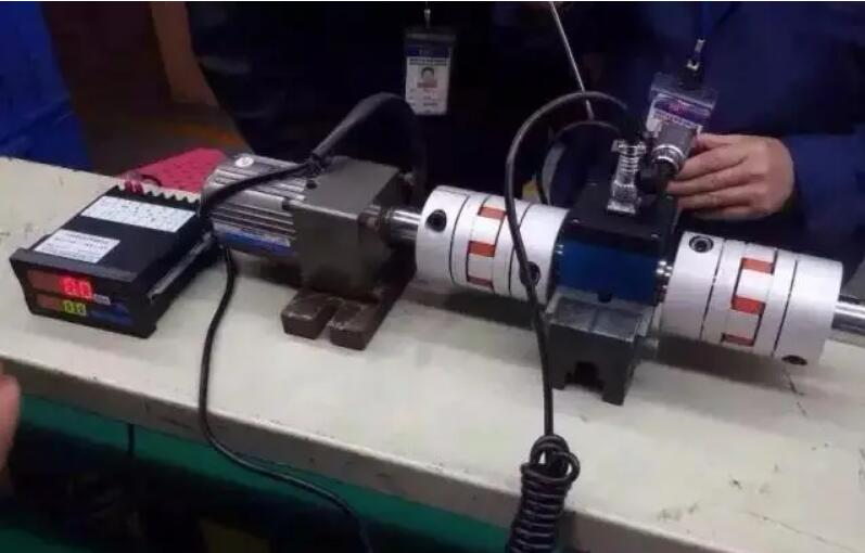
Explosion Proof Ultrasonic Level Sensors Operating Principle

Explosion-proof ultrasonic level sensors are devices designed to measure the level of liquids or solids in hazardous environments, where explosive gases or dusts are present. They are specifically constructed to prevent explosions by using materials and designs that can withstand sparks or high temperatures.

Explosion-proof ultrasonic level sensors use sound waves to measure liquid levels without touching the liquid. The sensor emits high-frequency sound waves that bounce off the surface of the liquid and calculate the distance between the sensor and the liquid level. This reading can be displayed on a screen or transmitted to a control system. These sensors are safe for hazardous environments because they don’t touch the liquid.

Read more about: Ultrasonic level measurement

Factors to Consider When Choosing Explosion Proof Ultrasonic Level Sensors

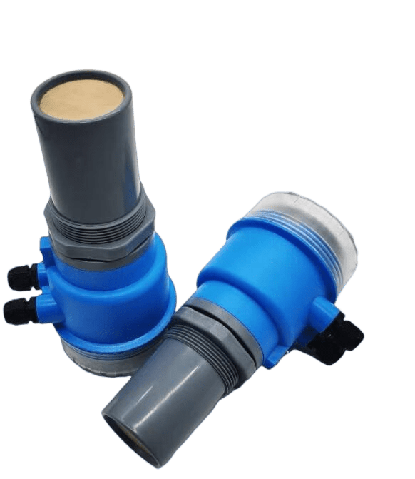
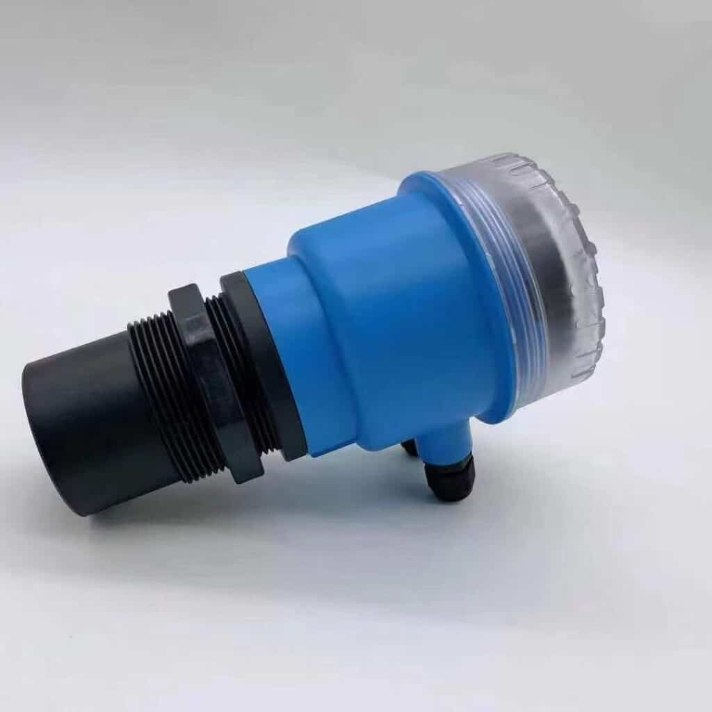
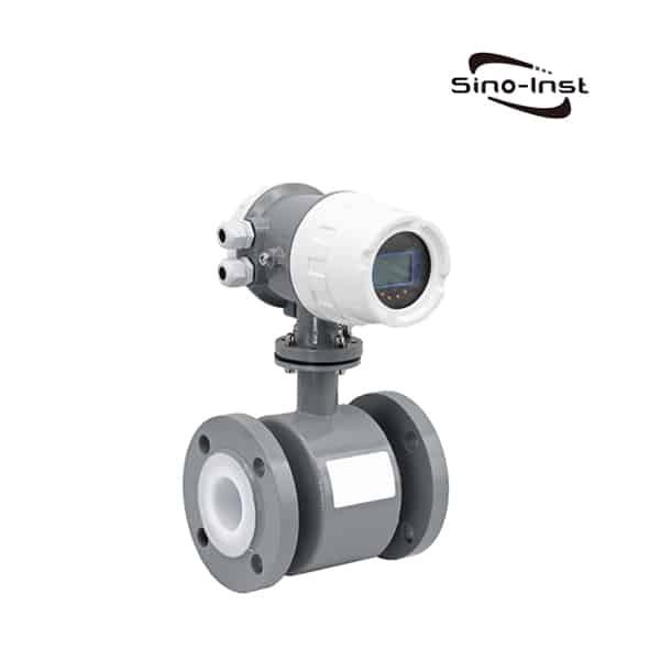
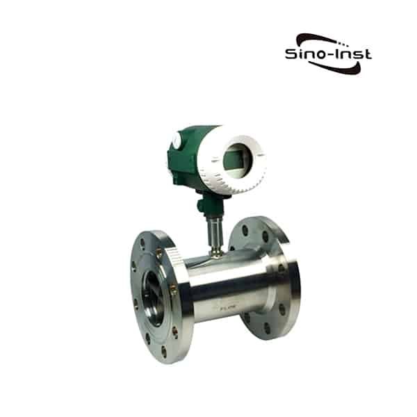
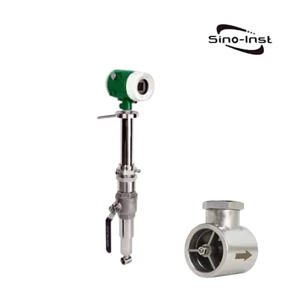
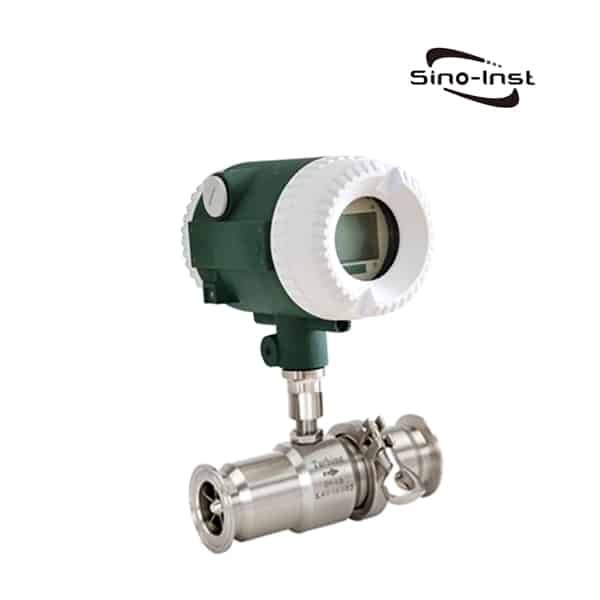
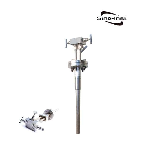
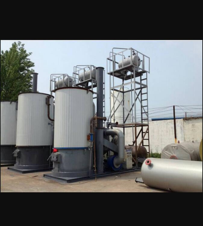
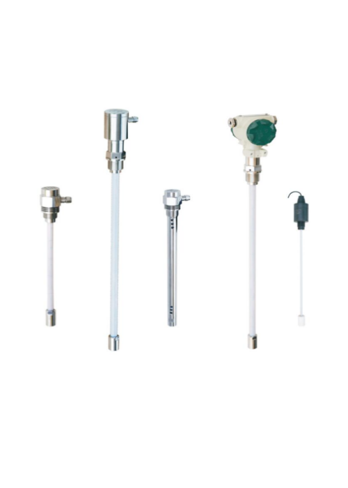
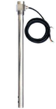
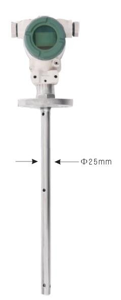
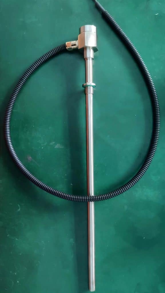
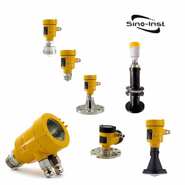
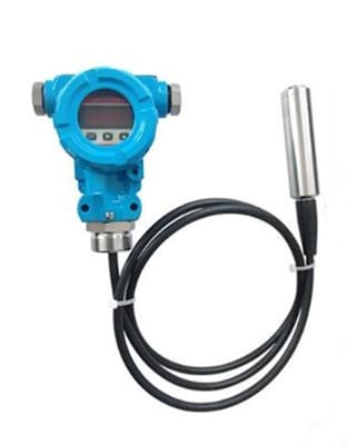
Explosion Proof Ultrasonic Level Sensor is a non-contact liquid level measuring instrument that is easy to install and maintain. It is widely used to measure flammable and explosive liquids such as diesel oil and crude oil, or to measure the height of liquids in explosion-proof environments.

When selecting an explosion-proof ultrasonic liquid level sensor, the following points need to be considered:

  1. The type of medium to be measured (liquid or solid, specific name: clean water, sewage, mud, gasoline, diesel, toluene, sulfur dioxide, etc.).
    • If liquid: Is there steam, fog, foam, waves, agitation, floating objects on the level?
    • If solid: is it solid? Is there dust?
  2. Minimum to maximum temperature and minimum to maximum pressure of the medium;
  3. Corrosive to the medium. If it is placed in a tank, it is necessary to know the material of the tank and whether there is an anti-corrosion lining;
  4. Whether explosion-proof and anti-corrosion are required;
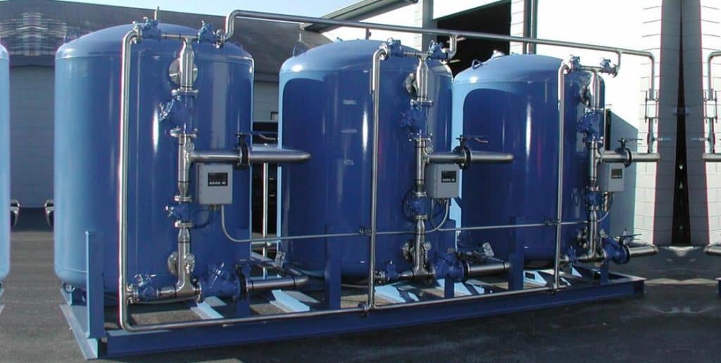
  5. Working environment: such as open ponds, covered ponds, horizontal tanks, vertical tanks, spherical tanks, storage tanks, etc.;
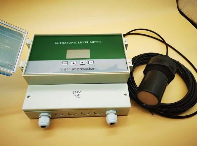
  6. Working voltage: 24VDC or 220VAC;
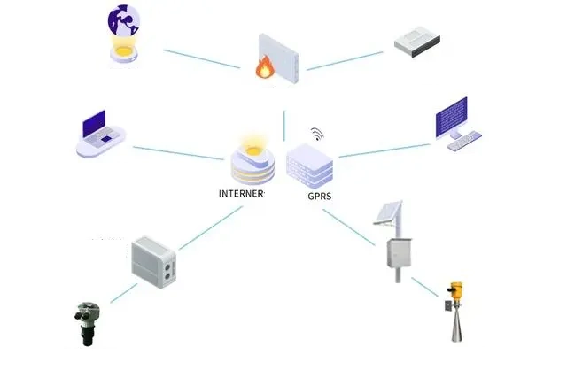
  7. Output signal: 4~20mA current, 485 communication output, relay output;
  8. Equipment type: split or integrated.

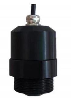
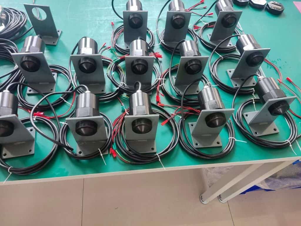
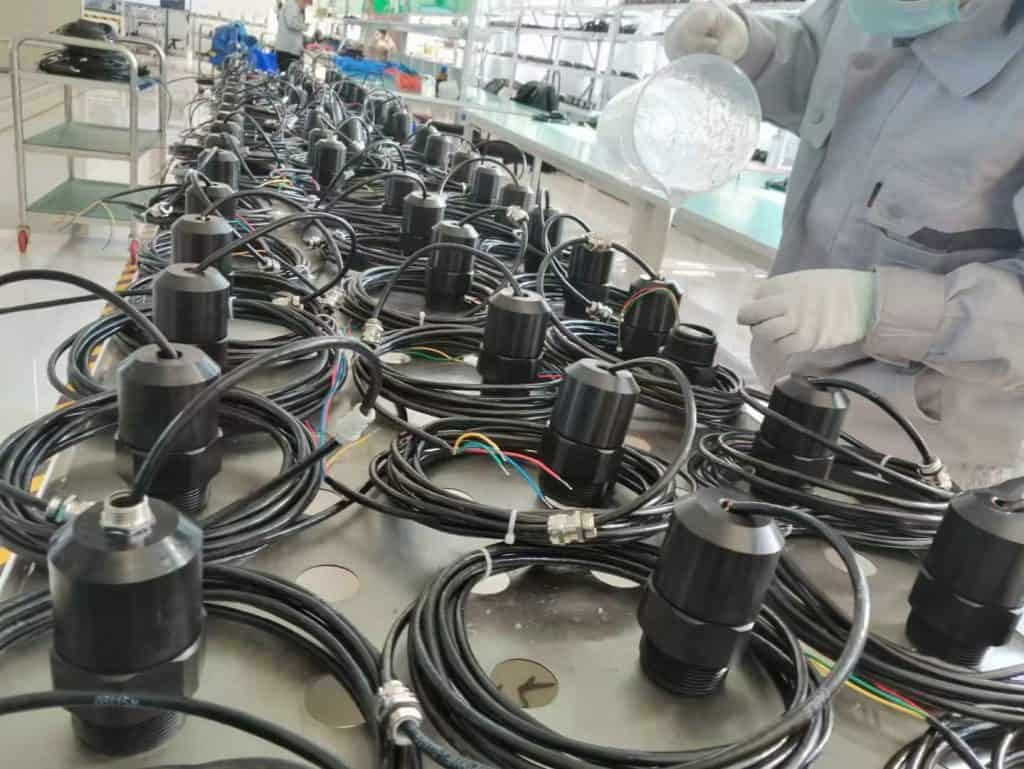
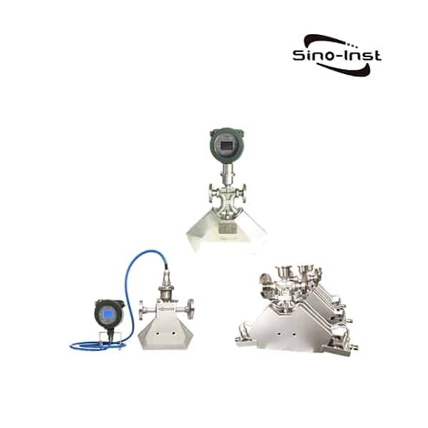
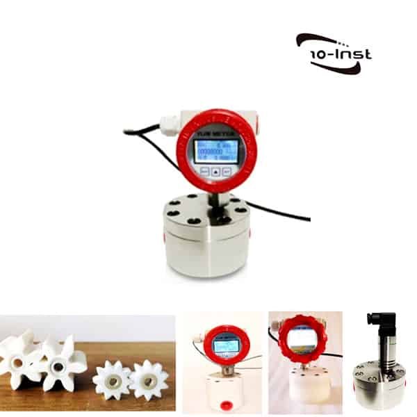
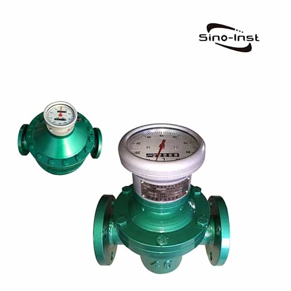
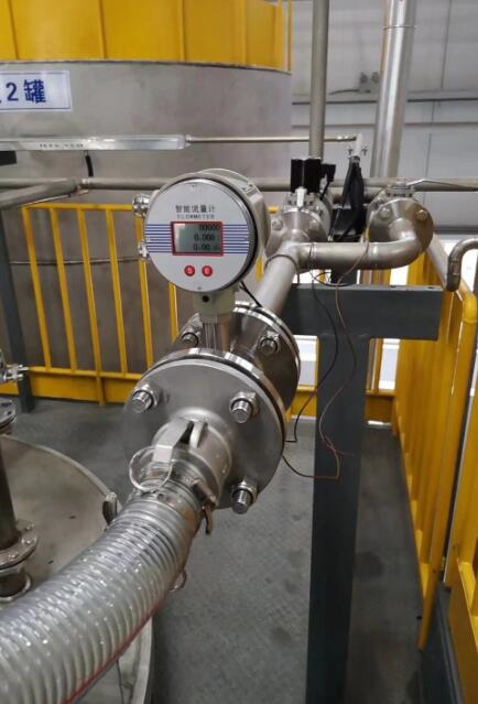
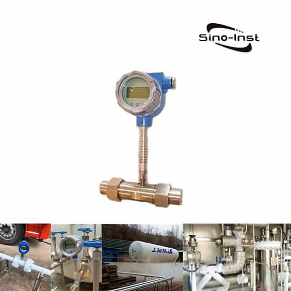
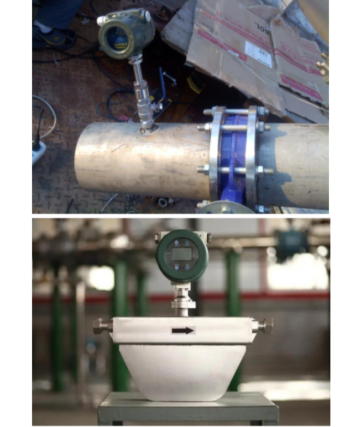
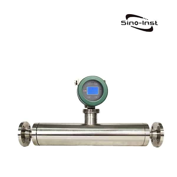
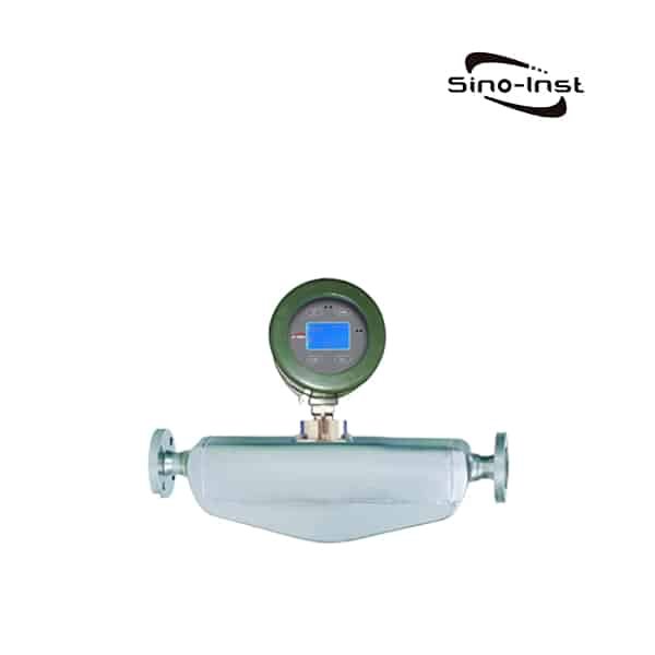
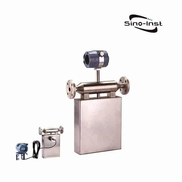
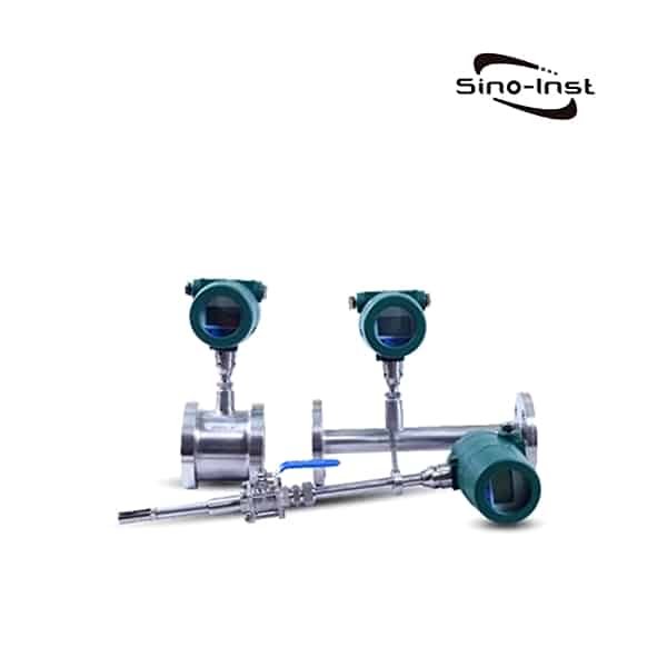
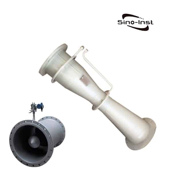
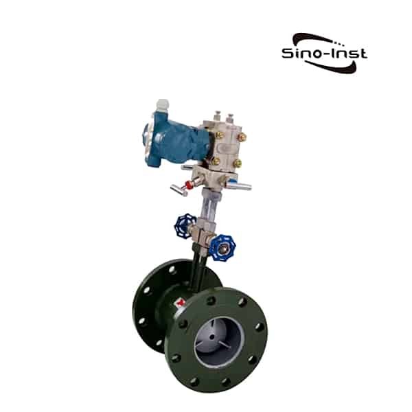
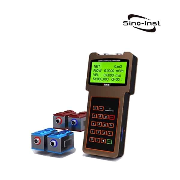
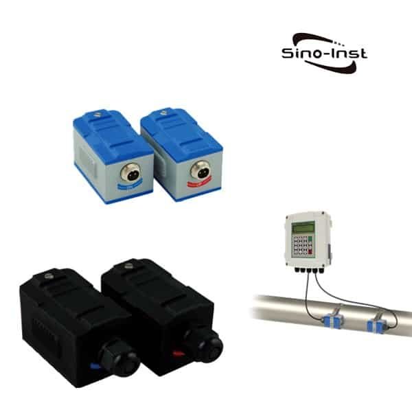
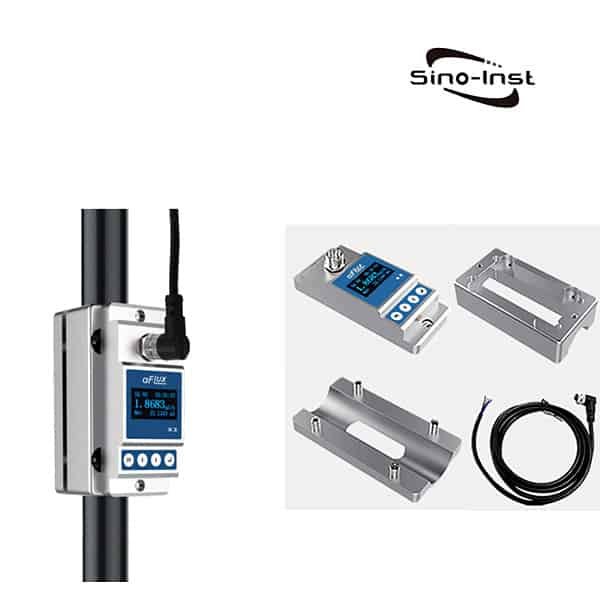
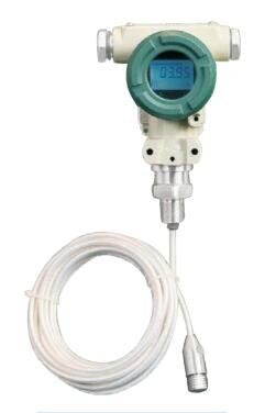
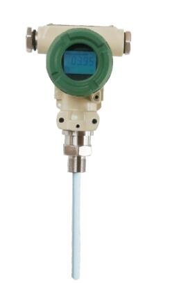
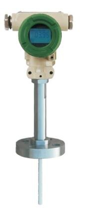
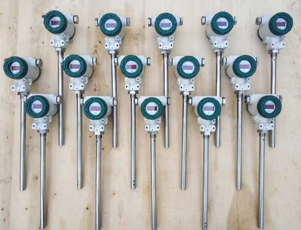
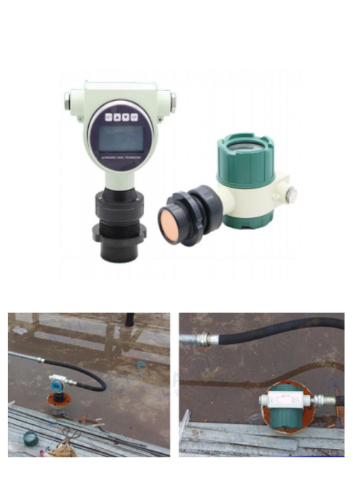
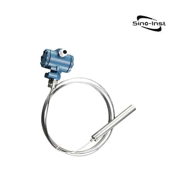
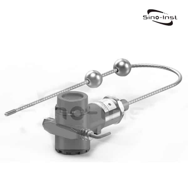
Featured Explosion Proof Ultrasonic Level Sensors we supply.

Explosion Proof Ultrasonic Level Sensor Price

Of course, in addition to the above parameters, the price is also one of the important parameters we need to consider. Sino-Inst manufactures and supplies Explosion Proof Ultrasonic Level Sensors. Has a price advantage. Refer to Explosion Proof Ultrasonic Level Sensor FOB price USD 470.00/pc.
You can contact our sales engineers to get detailed prices, or apply for sales discounts!

Read more about: What Is the Difference Between Class 1 Div 1 and Class 1 Div 2 ?

Notes on Explosion Proof Ultrasonic Level Sensor

  1. If the instrument is used outdoors, a sun visor or a protective box should be installed. To prevent the LCD screen from aging due to long-term sunlight exposure.
  2. If it is used in an environment with corrosive gas, an anti-corrosion sleeve must be installed, and the instrument shell and the inlet and outlet terminals must be tightened.
  3. If it is used in a place with corrosive gas or liquid, or at the seaside or at sea, the anti-corrosion type must be selected.
  4. The wire and cable protection tube should be sealed to prevent water accumulation and bites by rodents such as mice.
  5. Although the instrument has its own lightning protection device. However, when using the instrument in an area prone to lightning strikes, it is recommended to install a special lightning protection device at the entrance and exit of the instrument.
  6. When the instrument is used in a particularly hot and cold place, that is, when the ambient temperature may exceed the working requirements of the instrument, it is recommended to install a high and low temperature protection device around the liquid level instrument.
  7. The ultrasonic probe should be perpendicular to the measured liquid level, and there should be no other obstacles within the range of the ultrasonic emission cone.
  8. For use at <20°C or >60°C, please contact the technical service department in advance.
  9. There is dust, steam and mist in the environment. If there are foams, floats, liquid agitation, waves, etc., please contact the technical service department first.

Read more about Advantages Of Ultrasonic Level Sensors.

More Ultrasonic Level Sensor Applications and Markets

Ultrasonic Water Level Sensors

Ultrasonic sensor for water level measurement Ultrasonic Water Level Sensor refers to the ultrasonic level sensor used to measure the…

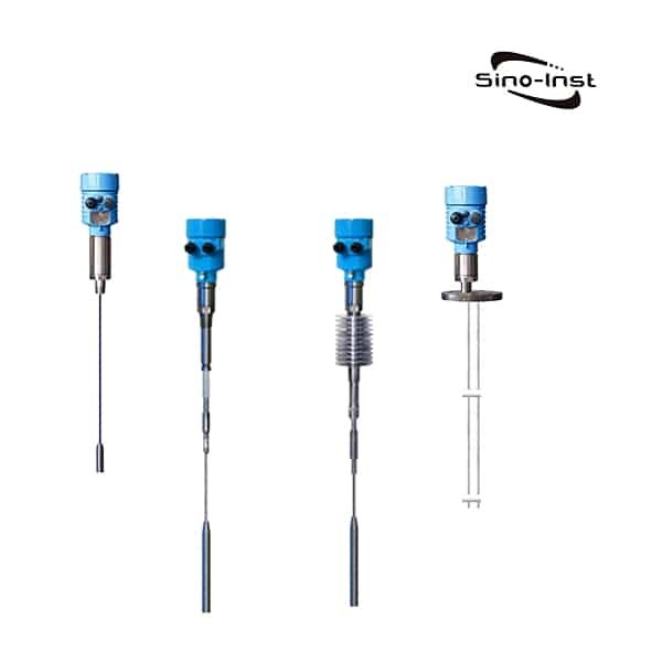
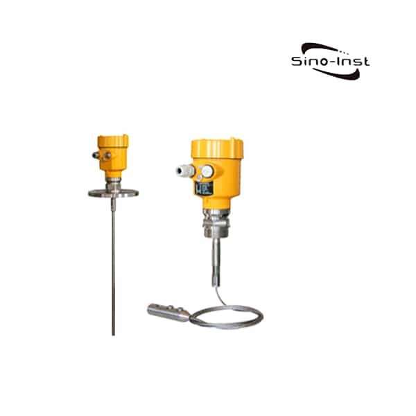
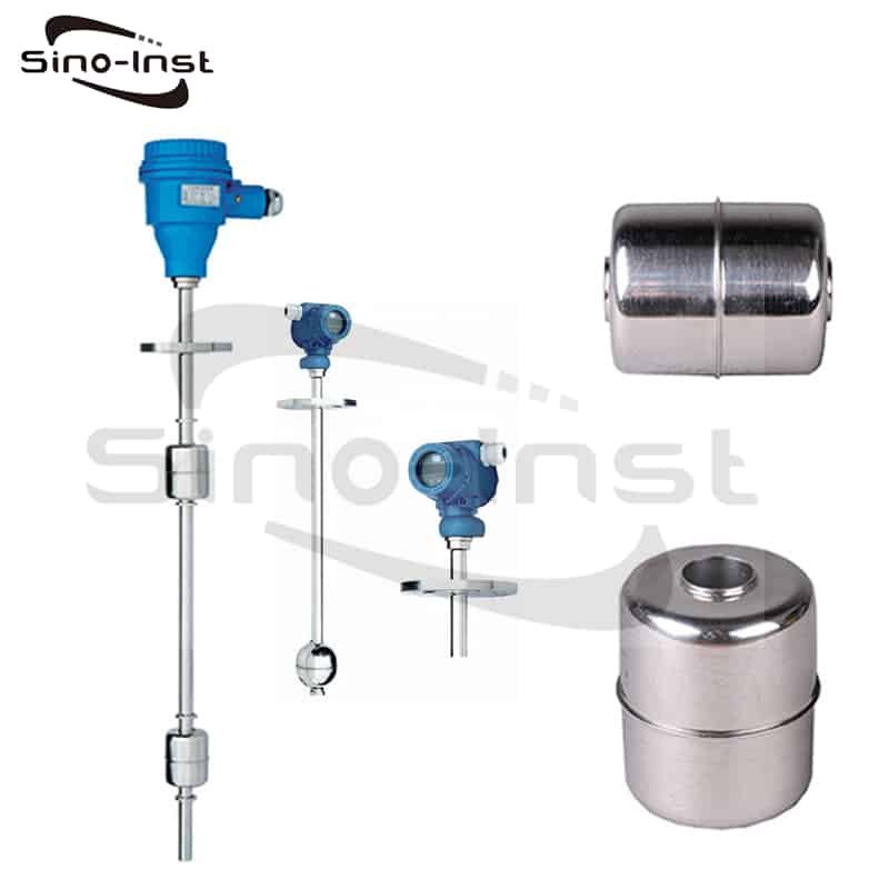
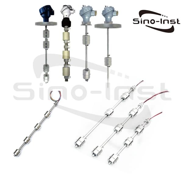
More Explosion Proof Level Sensors

An explosion proof level sensor is a type of sensor that is housed within a durable casing capable of containing an explosion or flame. This type of sensor is utilized in situations where it is not feasible to decrease the amount of electrical circuit energy being used.

Sino-Inst provides a variety of Explosion Proof Level Sensors, which have passed the CNEX explosion-proof certification.

Read more about: Ultrasonic Level Sensors for Liquids Applications

In conclusion, choosing the right explosion proof ultrasonic level sensor is crucial for ensuring safety and accuracy in hazardous environments.
When selecting a sensor, it is important to consider factors such as the application environment, accuracy requirements, and certifications compliance. By understanding these key factors and evaluating the top products available on the market, you can make an informed decision that meets your specific needs.

Remember to always prioritize safety and follow installation and maintenance procedures carefully. With the right explosion proof ultrasonic level sensor, you can accurately measure liquid levels without any risk of explosion.

Request a Quote

Please enable JavaScript in your browser to submit the form

Different Types of Flowmeters – Technical and Application Analysis

Different Types of Flowmeters Flowmeters are devices used to measure the flow rate of different liquids, steam or gases in a line. They come in different types, such as mechanical, ultrasonic, and magnetic flowmeters.
Mechanical flowmeters use a positive displacement flow measuring device to determine the volume of the fluid passing through. Ultrasonic flowmeters use an ultrasonic sensor to determine the velocity of the fluid, while thermal flowmeters use heat to measure the flow rate. Orifice plates and magnetic flowmeters are some of the most common types of flowmeters used in industry.
Understanding the different types of flowmeters and their principles of operation is essential to selecting the right measuring device for a particular application.

What is a Flow Meter?

A flow meter is a device that measures the amount of liquid, steam or gas that passes through a specific point in a pipe or conduit. It is used in various industries to monitor and control the flow of fluids in pipelines, such as water, oil , gas, or chemicals.

Flow meters can be mechanical, electronic, or ultrasonic, and they work by measuring the velocity, volume, or mass of the fluid.

Flow meters are essential for ensuring that fluid flow rates remain within acceptable limits. And they help prevent damage to equipment and systems due to overloading or underloading. They are also critical in maintaining product quality and process efficiency.

Types of Flowmeters

There are various types of flowmeters used to measure fluid flow, including mechanical, electronic, and ultrasonic. Each type measures the flow rate of a fluid in a different way. Each type of flowmeter has its advantages and disadvantages.

We’ll take a look at the 5 main types of flowmeters that can be found on the market today. Includes differential pressure flowmeters, velocity flowmeters, positive displacement flowmeters, mass flowmeters and open channel flowmeters. More types of flowmeters from Wikipedia.

Differential Pressure (DP) Flowmeters

Differential Pressure (DP) Flowmeters measure fluid flow by detecting the pressure drop across an throttle placed in the flow path, such as an orifice plate, venturi tube, or flow nozzle. The greater the flow rate, the higher the pressure drop, and the flow rate can be calculated based on the pressure difference. DP Flowmeters are widely used due to their simplicity and low cost, and they can be used to measure both liquids and gases.

There are several types of DP Flowmeters, each with its unique design and advantages. Here are some of the most common types:

  • Orifice Plate Flowmeters: They have a circular plate with a hole in the middle that creates a pressure drop as the fluid flows through it.
  • Venturi Flowmeters: They have a conical shape that narrows down the flow path, which causes an increase in fluid velocity and a decrease in pressure.
  • Flow Nozzle Flowmeters: They have a converging inlet section, a throat section, and a diverging outlet section that create a pressure drop across the nozzle.
  • Pitot Tubes: They measure the fluid velocity by detecting the pressure difference between the stagnation point and the point where the fluid flow is parallel to the tube’s axis.

Each type of DP Flowmeter has its advantages and disadvantages, and the best choice depends on the specific application requirements.

Read more about: Differential Pressure Flow Meter Calculation Formula and Calculation Examples; How to Calculate Pressure Drop in a Pipe?

Positive Displacement (PD) Flowmeters

Positive Displacement (PD) Flowmeters measure fluid flow by trapping and measuring the amount of fluid that moves through the meter. The principle of operation is based on the movement of the fluid through a chamber of fixed volume, causing a displacement of the fluid. The flow rate is calculated based on the number of times the chamber is filled and emptied. PD Flowmeters are highly accurate and suitable for measuring low flow rates of both viscous and non-viscous liquids.

There are several types of PD Flowmeters, each with its unique design and advantages. Here are some of the most common types, along with their advantages and disadvantages:

Type of PD FlowmeterPrinciple of OperationAdvantagesDisadvantages
Piston FlowmetersUse a piston moving inside a chamber to measure fluid flow.Highly accurate; Suitable for low to high viscosity fluidsNot suitable for measuring fluids with suspended solids
Oval Gear FlowmetersTwo oval gears rotating in opposite directionsHighly accurate; Suitable for low to medium viscosity fluidsAffected by fluid temperature and viscosity changes
Nutating Disc FlowmetersA disc that “nutates” or wobbles to trap and measure fluid flowHighly accurate; Suitable for low viscosity fluidsAffected by fluid temperature changes
Rotary Vane FlowmetersA rotor with vanes that rotate inside a chamberHighly accurate; Suitable for low to high viscosity fluidsNot suitable for measuring fluids with suspended solids

More details about: PD Flow Meters Selection and Application | Oil-Liquid

Velocity Flowmeters

Velocity Flowmeters measure fluid flow by determining the velocity of the fluid as it flows through the meter. The principle of operation is based on the relationship between the velocity of the fluid and the pressure difference created by the fluid’s motion. Velocity Flowmeters are commonly used for measuring high flow rates of fluids such as water, steam, and gases, and they are often less expensive than other types of flowmeters.

Here are some of the most common types of Velocity Flowmeters along with their advantages and disadvantages:

Type of Velocity FlowmeterPrinciple of OperationAdvantagesDisadvantages
Turbine FlowmetersTurbine rotor spins as fluid flows through itHighly accurate; Suitable for clean fluids with low to medium viscosityAffected by changes in fluid density, temperature, and viscosity
Electromagnetic FlowmetersFaraday’s Law to measure voltage generated by fluid flow through a magnetic fieldHighly accurate; Suitable for measuring conductive fluids such as water and acidsNot suitable for measuring non-conductive fluids
Vortex FlowmetersMeasure fluid flow using the principle of the Karman vortex streetHighly accurate; Suitable for clean fluids with low to medium viscosityCan be affected by changes in fluid density
Ultrasonic FlowmetersUse ultrasonic sensors to measure the time it takes for an ultrasonic signal to travel between two points in the fluid flowHighly accurate; Suitable for measuring fluids of different viscosities, densities, and conductivitiesOften more expensive than other types of flowmeters

Mass Flowmeters

Mass Flowmeters measure the mass flow rate of fluids passing through them, rather than measuring volume or velocity. They work on the principle of thermal dispersion or Coriolis effect, and they can measure the flow rate of both liquids and gases accurately. Mass Flowmeters are highly sensitive and provide accurate readings even with changes in fluid properties, making them ideal for a wide range of industrial applications.

Coriolis Meters:

Coriolis Meters measure fluid flow using the Coriolis effect. The meter consists of a vibrating tube, and as the fluid flows through the tube, it causes a change in the tube’s vibration frequency, which is measured by sensors.

The advantages of Coriolis meters include high accuracy and stability, excellent repeatability, and the ability to measure a wide range of fluids, including liquids and gases.

However, they can be costly, and their performance can be affected by the presence of solid particles or gas bubbles.

Thermal Mass Flow Meters:

Thermal Mass Flow Meters measure the mass flow rate of fluids by detecting the heat transfer from a heated element to the fluid. As the fluid flows over the heated element, it cools it down, and the change in temperature is measured by temperature sensors.

The advantages of Thermal Mass Flow Meters include high accuracy, the ability to measure both liquids and gases, and their simplicity of design.

However, they can be affected by changes in fluid temperature and viscosity, and they may require recalibration if the fluid properties change.

Open Channel Flowmeters

Open Channel Flowmeters are used to measure the flow rate of liquids in open channels, such as rivers, streams, and irrigation canals. They work by using a primary device, such as a flume or weir, to create a constriction in the channel, which causes the liquid to rise and flow through the device. The flow rate is then determined by measuring the height of the liquid above the device and using a formula to calculate the flow rate.

Type of FlowmeterPrinciple of OperationAdvantagesDisadvantages
FlumesSpecially designed constrictionHigh accuracy, low cost, ease of installationAffected by changes in channel shape, require certain amount of head loss
WeirsSharp-crested structureHigh accuracy, low cost, ease of installationAffected by changes in channel shape, require certain amount of head loss
Area-Velocity MetersMeasure velocity at multiple points and combine with cross-sectional areaHigh accuracy, measure flow rates in irregular channels, measure both forward and reverse flowMore complex and costly than other open channel flow meters
Ultrasonic Doppler MetersUse sound waves to measure velocityHigh accuracy, measure flow rates in irregular channels, measure both forward and reverse flowAffected by changes in liquid’s acoustic properties, may require calib

How to select a flow meter?

Here are some of the key parameters that can affect the selection of a flowmeter for a particular application:

  1. Fluid type and properties, such as viscosity, density, and corrosiveness
  2. Flow rate range and required accuracy
  3. Operating conditions, such as temperature, pressure, and fluid velocity
  4. Installation requirements, such as the orientation and size of the pipe
  5. Availability of power or signal inputs for the flowmeter
  6. Environmental conditions, such as the presence of hazardous or explosive materials
  7. Required maintenance and calibration intervals
  8. Compatibility with existing control systems or instrumentation
  9. Cost and budget considerations.

Here are some recommendations for selecting flowmeters for specific fluid applications:

  • For CORROSIVE LIQUIDS: Magnetic flowmeters or Ultrasonic flowmeters can be selected.
  • For HIGH VISCOSITY LIQUIDS: Positive Displacement (PD) flowmeters or Turbine flowmeters can be selected.
  • For STEAM: Vortex flowmeters or DP flowmeters with a flow computer can be selected.
  • For GAS: Thermal Mass flowmeters or vortex flowmeters can be selected.
  • For FOOD AND BEVERAGE: Electromagnetic flowmeter, turbine flow meters or Ultrasonic flowmeters can be selected.
  • For OIL AND GAS: Coriolis flowmeters, gear flow meters, turbine flow meters or Ultrasonic flowmeters can be selected.
  • For HVAC: Thermal flowmeters or Vortex flowmeters can be selected.
  • For WATER TREATMENT: Electromagnetic flowmeters or Ultrasonic flowmeters can be selected.

It’s important to note that the selection of a flowmeter should be based on the specific needs of the application, and factors such as accuracy, repeatability, cost, and installation requirements should be considered when making a selection.

More Flow Measurement Technologies and Applications

Slurry Flow Meter

Flow Meter for Slurry Application Slurry is a product of domestic sewage and industrial wastewater treatment. Slurry consists of solid…

BTU Meter for Chilled Water

What is BTU Meter for Chilled Water? The BTU Meter for Chilled Water accurately measures the thermal energy consumed by…

In conclusion, the proper selection and use of Types of Flowmeters are crucial for accurate and reliable measurement of fluid flow in various industrial processes. Each types of flowmeter has its own advantages and limitations, which should be carefully considered before making a decision. However, Sino-Inst, as a leading manufacturer of flowmeters, has various advantages that make it an ideal choice for customers in need of high-quality flow measurement solutions.

With years of experience and expertise, Sino-Inst offers a wide range of flowmeters, including differential pressure, positive displacement, velocity, mass, and open-channel flowmeters, to meet different application needs. Additionally, Sino-Inst provides customized solutions, comprehensive technical support, and excellent after-sales services to ensure customer satisfaction.

Whether you need a flowmeter for liquid, gas, or steam applications, Sino-Inst has the right solution for you. We are committed to providing the best products and services to help our customers improve their processes and achieve their goals. Contact us today to learn more about our flowmeters and how we can help you.

Request a Quote

Please enable JavaScript in your browser to submit the form

What Is a Torque Transducer? How to Choose?

Torque transducers are essential tools in many industries that rely on precise measurements of rotational forces. These devices play a crucial role in measuring the torque produced by engines, motors, and other rotating systems.
Whether you’re working in the automotive, aerospace, or manufacturing industry, understanding what a torque transducer is and how to choose the right one is crucial for optimizing performance and ensuring accuracy.
In this blog post, we’ll explore everything you need to know about torque transducers, including their types, applications, and factors to consider when selecting one for your specific needs.

What is torque?

Torque is a term used to describe the twisting or rotational force applied to an object. You can think of it as the force that causes an object to rotate around a fixed axis, like a wheel turning on an axle.

Torque is measured in units of force times distance, such as pound-feet or newton-meters.

In everyday life, you might experience torque when tightening a bolt with a wrench or using a crank to turn a wheel.

In the world of engineering and physics, torque plays a critical role in understanding how machines and engines work, and how to measure and optimize their performance.

More about torque definition and calculation.

What Is a Torque Transducer?

A torque transducer is a device that measures the amount of twisting or rotational force (torque) applied to a rotating system.

It’s like a scale for measuring the torque produced by machines and engines.

Torque transducers can be used in a wide range of industries, such as automotive, aerospace, and manufacturing, to optimize performance and ensure accuracy.

There are different types of torque transducers, including strain gauge, magnetoelastic, and optical, which work by different principles to measure torque.

By providing accurate measurements of torque, torque transducers help engineers and technicians understand how machines and engines are performing and make improvements where necessary.

Torque Transducer Measurement Principle

The measurement principle of a torque transducer is all about detecting and measuring the twisting or rotational force applied to a rotating system.

Torque transducers work by using different methods, such as strain gauges, magnetoelasticity, or optical technology, to sense the amount of torque being applied.

For example, strain gauges work by measuring the electrical resistance of a metal strip that changes as it stretches or compresses in response to the applied torque.

The magnetoelastic type, on the other hand, uses a magnet and a magnetic field to sense changes in the shape of a metal element.

In each case, the torque transducer converts the twisting force into a measurable electrical signal, which can be analyzed and used to optimize the performance of the machine or engine.

Types of torque transducers

Type of Torque TransducerMeasurement PrincipleAdvantagesDisadvantages
Strain GaugeUses metal strip to change resistance when twistedAccurate and cost-effective; Good for low-torque applicationsCan be sensitive to temperature changes
MagnetoelasticUses magnetic field to measure torqueHighly accurate and durable; Good for high-torque applicationsCan be expensive
OpticalUses light to detect changes in material’s propertiesHighly accurate and non-contact; Good for high-speed applicationsCan be expensive and sensitive to vibration
Rotary TransformerUses two coils and a magnetic field to measure torqueHighly accurate and durable; Good for high-torque applicationsCan be expensive and sensitive to temperature changes
HybridCombines two or more principles for more precise measurementCan offer advantages of multiple typesCan be more complex and expensive

Static / Reaction Torque vs. Rotary Torque

When it comes to measuring torque, there are two main types: static/reaction torque and rotary torque.

Static torque refers to the twisting force applied to a non-moving object, such as a bolt or a nut.

Rotary torque refers to the twisting force applied to a rotating object, such as a motor or an engine.

Static torque measurement is important for applications where a component needs to be tightened to a specific torque value, such as in the automotive or aerospace industry.

Rotary torque measurement, on the other hand, is critical for assessing the performance of rotating machinery and ensuring its efficiency and longevity.

Both static and rotary torque measurement have their own unique challenges and require different types of torque transducers.

Understanding the differences between these two types of torque measurement is essential for selecting the appropriate torque transducer for a specific application.

Featured Torque Transducers for Sale

Industrial Applications of Torque Transducer:

Here are some common industrial applications of torque transducers:

  • Automotive industry: measuring the torque applied to bolts during assembly process.
  • Aerospace industry: measuring the torque in engines, turbines, and other rotating machinery.
  • Energy industry: measuring the torque in wind turbines, generators, and other equipment.
  • Manufacturing industry: measuring the torque in production equipment such as lathes and drills.
  • Medical industry: measuring the torque applied to medical instruments during surgical procedures.
  • Research and development: testing the performance and characteristics of new materials and products.
  • Robotics: measuring the torque applied to robotic joints and motors to ensure accuracy and safety.

These are just a few examples of the many industrial applications of torque transducers.

How to choose a Torque Transducer for your application?

Choosing the right torque transducer for your application can be a daunting task, as there are many factors to consider.

Here are some key factors to keep in mind when selecting a torque transducer:

  • Torque range: Make sure the transducer’s torque range is appropriate for your application’s needs.
  • Accuracy: Determine the level of accuracy required for your application and choose a transducer that meets those requirements.
  • Sensitivity: Consider the sensitivity of the transducer to external factors. Such as temperature, vibration, and electromagnetic interference.
  • Speed: Determine the speed at which torque measurements need to be taken and choose a transducer that can provide measurements at that speed.
  • Signal output: Consider the type of signal output required. Such as analog or digital, and ensure that the transducer can provide the necessary signal.
  • Environment: Consider the environment in which the transducer will be used. Including temperature, humidity, and the presence of corrosive materials.
  • Durability: Choose a transducer that is durable enough to withstand the demands of your application.

By considering these factors, you can select a torque transducer that is appropriate for your specific application and provides accurate and reliable measurements.

More Torque and Pressure Measurement Solutions

Stationary Torque Transducers

Stationary Torque Transducers are also called Static Torque Transducers, or Stationary Transducers. Static torque transducers are compact, robust and maintenance-free,…

Conclusion

Torque transducers are an essential tool for measuring torque in various industrial applications. Whether you are in the automotive, aerospace, energy, manufacturing, or medical industry, selecting the right torque transducer is crucial for ensuring optimal performance, safety, and reliability.

By considering factors such as torque range, accuracy, sensitivity, speed, signal output, environment, and durability, you can select a torque transducer that meets the unique requirements of your application.

If you need to purchase a torque transducer or have any related technical questions, feel free to contact Sino-Inst. We specialize in providing high-quality torque transducers that are reliable, accurate, and durable. Our team of experts is always ready to assist you in selecting the right torque transducer for your specific needs. Contact us today to learn more!

Request a Quote

Please enable JavaScript in your browser to submit the form

How to Measure River Water Level?

River water level monitoring is very important. There are many places where remote water level monitoring is required. Such as factory reservoirs, reservoirs for farmland irrigation, water towers for water supply, river courses, dams, etc. It is important to do a good job of remote monitoring of water levels.

Real-time monitoring of water level is also an important part of water conservancy projects, river management, flood control and disaster reduction and other fields.

There are many ways to Measure River Water Level. We only discuss the most ideal two kinds here: radar water level meter and ultrasonic level meter.

Common River Water Level Measurement Methods

The river water level monitoring system can monitor the water level in real time, which is an important link in the fields of water conservancy engineering, river management, flood control and disaster reduction.

How is the water level measured in a river?
What are the common river water level monitoring methods?

  • Radar water level meter
  • Ultrasonic level meter
  • Video method
  • Electrometry
  • Water gauge measurement;
  • Electronic water gauge;
  • Float level gauge;
  • Pressure water level transmitter;
  • Laser water level meter, etc.

Among them, the water gauge is used for manual observation. Other methods are used for automatic observation.

Extended reading: What Is The Difference Between A Point-Level Sensor And A Continuous Level Sensor?

In practical application scenarios, Radar water level meter and ultrasonic level meter have more advantages in monitoring water level.
Next, let’s take a closer look.

radar water level meter

  • Measuring medium: water
  • Measuring range: 0.05m~60m
  • Process connection: G1½A / 1½NPT thread / bracket
  • Process temperature: -40~80℃
  • Process pressure: -0.1~0.3 MPa
  • Antenna size: 42mm lens antenna
  • Antenna material: PTFE
  • Accuracy: ±1mm
  • Protection class: IP67
  • Center frequency: 76GHz~81GHz
  • Launch angle: 6°
  • Power supply: Two-wire system/DC24V
  • Four-wire system/DC24V
  • Four-wire system/AC220V
  • Shell: aluminum (with display)
  • Signal output: RS485 Modbus
  • Display: with display/without display

More about: How does a radar liquid level sensor work?

Advantages of radar water level meters

  1. Low power consumption;
    • The radar water level gauge has low power consumption. The pulse radar water level gauge consumes less than 0.5W. The power consumption of frequency modulation continuous wave radar water level gauge is about 1W. Low power consumption, very suitable for use in solar power supply systems in the wild in mountainous areas.
  2. Easy installation;
    • The radar water level gauge is suspended and installed without additional civil work and land occupation. It can be installed and used in channels, pipelines and rivers
  3. Low maintenance;
    • The radar water level gauge is basically maintenance-free;
    • Non-contact measurement, not limited to the water quality environment, does not damage the water flow structure;
  4. High measurement accuracy, not affected by water level changes;
    • The accuracy of the radar water level gauge can reach 3mm, and the resolution is 1mm. Large measuring range (up to 70 meters or more);
  5. The data is stable and reliable;
    • Not affected by environmental factors such as temperature, humidity, wind speed, rainfall, etc.
  6. Scalability and integration
    • The radar water level gauge can be integrated into the flow monitoring system, water and rain monitoring system, mountain torrent early warning and monitoring system, etc., with high scalability and integration.
  7. Low dependence on the network, low tariffs, and better environmental adaptability.
  8. It is suitable for open water bodies such as reservoirs, lakes, rivers, channels, etc. And water level monitoring projects in small spaces such as inspection wells and tanks. And it can be used in high temperature, high pressure and highly corrosive installation environment.

List of Radar Level Sensors

Ultrasonic water level meter

Measurement rangeLiquid: 0~15m/20m/30m/40mSolid: 0~6m/10m /15m /25m
Blind Area0~15m:0.6m;0~20m:0.8m;0~30m:1.2m;0~40m:1.5m
Accuracy (in air)0.2% of the measuring range
Current Output4~20mA
Output Resolution0.03% of the actual range
Output Load0~500Ω
Switching OutputHigh and low relays normally open
Relay SpecificationsAC250V 5A/DC30V
Display Resolution1 cm
Display Method4-digit LCD (character height 15cm) or 6-digit LED digital tube
Input PowerDC24V (±10%) 80mA or AC220V 50mA
Temperature compensationFull range auto
Medium temperature-45℃~+85℃
Pressure range±0.1MPa
Acoustic beam angle5°(3TL)
Detection period1second
Parameter setting3 position sense button
Cable devicePGl3.5 sealing sleeve
Housing materialABS
Sensor materialPVC
Protection levelIP67
Installation methodThread (flange) or fixing hole (bracket)
Installation requirementsProbe emitting surface should protrude from the vessel mounting port

Featured Non Contact Ultrasonic Level Sensing Devices

Advantages of Ultrasonic level meters

Ultrasonic water level meter has outstanding advantages, which are mainly reflected in the following aspects:

  1. Adopt non-contact measurement, stable and reliable, not easily affected by liquid viscosity and density.
  2. Fixed-point continuous measurement is available, which is convenient for providing remote measurement and remote measurement signals.
  3. Simple structure, easy to read, easy to install and maintain.
  4. Safe and clean, the instrument has a long service life
  5. With temperature compensation function, it can be used in environments with large temperature differences, with high precision and strong adaptability.
  6. With RS-485 communication interface, special echo processing method is adopted to effectively avoid false echo.
  7. There are three ranges of 5m, 10m and 15m, which can be applied in different environments.
  8. High explosion-proof grade (explosion-proof 6Gb) and protection grade (up to IP66/IP67).
  9. The PVDF probe can ensure reliable measurement of the instrument in corrosive liquids or corrosive environments.
  10. High cost performance and low maintenance cost.

River water level monitoring system

The river water level monitoring system is mainly composed of radar water level meter or ultrasonic water level meter, monitoring host and server.

River water level meters are usually installed on the side of river bridges by wall-mounting. Can collect river water level data in real time. Report the data to the monitoring terminal through serial communication.

After the monitoring host receives the data reported by the detector, it communicates via wireless 4G/2G/NB-lot. Report the water level data to the background server in real time. Supervisors can keep abreast of the current river conditions through the business terminal.

The monitoring host usually uses a polymer lithium battery pack. Cooperating with the independent photovoltaic power supply system, it can provide stable power supply for the monitoring host for a long time.

Common communication methods for data transmission include 3G/4G, GSM/GPRS, etc. At present, the 4G mobile signals in the flood-prone areas of most cities have basically been covered. The good signal rate is very high. Have good communication conditions. Therefore, the water monitoring equipment can use 4G as the main channel to upload the monitoring data to the center. And it is backward compatible with 3G/GPRS as a backup channel.

More water level monitoring applications and markets

Laser Level Transmitter

What is a laser level transmitter? A laser level transmitter is also called a laser level meter. Industrial Accurate, non-contact,…

For measuring the liquid level of a river, whether using a radar water level meter or an ultrasonic water level meter, the most important thing is to achieve effective and stable measurement.

If you have any questions about the selection and installation of river water level meters, please feel free to contact our engineers.

Request a Quote

Please enable JavaScript in your browser to submit the form

What Is Turndown Ratio in Flow Meters

What Is Turndown Ratio in Flow Meters? In simple terms, turndown ratio refers to the range of flow rates that a flow meter can accurately measure. This ratio is a crucial factor in selecting the right flow meter for your application, as it determines the meter’s ability to measure low and high flow rates with precision and accuracy.

Choosing a flow meter with a high turnover ratio can save you money and increase efficiency by eliminating the need for multiple flow meters or reducing maintenance and calibration costs. In this blog post, we will explore turnover ratio in flow meters, its importance, and how it impacts various industries.

RFQ Flow Meters

Definition of turndown ratio

So, what exactly is turndown ratio?

Well, it’s the measurement range of a flow meter from the highest to the lowest flow rate it can accurately measure. Essentially, it tells you how much the flow rate can be turned down or decreased while still maintaining accurate readings.

For example, a flow meter with a turndown ratio of 10:1 can accurately measure flow rates from 100 L/H down to 10 L/H.

This ratio is an important consideration when selecting a flow meter for your application, as it determines the meter’s versatility and ability to handle varying flow rates.

A higher turndown ratio means more flexibility and potentially cost savings, as you may not need multiple flow meters for different flow rates.

Why is Turndown Ratio important?

In flow measurement, the turndown ratio indicates the range of flow over which the flowmeter can measure with acceptable accuracy. It is also known as adjustable range. This is very important when selecting a flow meter technology for a specific application.

If the airflow to be measured is expected to vary between 100,000 cubic meters per day and 1,000,000 cubic meters per day. The turndown ratio for a specific application is then at least 10:1. Therefore, the meter requires at least a 10:1 turndown ratio.

Formula for calculating Turndown Ratio

The turndown ratio can be expressed as:
TR = Q(max)/Q(min)

TR = Regulation Ratio
Q(max) = maximum flow
Q (min) = minimum flow

Example calculation

If the gas to be measured varies between 100000 m3/day and 1000000 m3/day.
This particular application has TR = 10:1.
The TR of the required flow meter should be at least 10:1
If the flow meter has a maximum flow rate of 2000000 m3/day, then the required turndown ratio (TR) will be 20:1

Typical turndown ratios for various flowmeters

The examples here are for gas flow, but the same gauge type can be used for liquids, with similar turndown ratios.

Different types of flow meters have varying turnover ratios. Here are some common flow meters and their typical turnover ratios:

It’s important to note that these are general ranges and actual turnover ratios may vary depending on the specific model, size, and operating conditions. When selecting a flow meter, it’s crucial to consider the turnover ratio and ensure that it can accurately measure the flow rate needed for your application.

Choosing the right flow meter for your application

Selecting the right flow meter for your application is crucial to ensure accurate and precise measurements. Here are some key considerations when choosing a flow meter:

  • Flow rate range: Consider the expected flow rate range and select a flow meter with an appropriate turndown ratio.
  • Fluid properties: The properties of the fluid being measured, such as viscosity and corrosiveness, can affect the selection of a flow meter.
  • Environmental conditions: The operating environment, such as temperature and pressure, can impact flow meter performance.
  • Accuracy requirements: Consider the level of accuracy required for your application and select a flow meter that meets those requirements.

To maximize the turndown ratio of your flow meter, follow these best practices:

Proper installation: Ensure that the flow meter is installed correctly according to manufacturer specifications.

Regular calibration: Regular calibration of the flow meter is essential to maintain accuracy.

Maintenance: Proper maintenance of the flow meter, such as cleaning and inspection, can prolong its lifespan and improve performance.

Avoiding extremes: Avoid operating the flow meter at the extreme ends of its turndown ratio range, as accuracy may be compromised.

By considering these factors and following these best practices, you can select and maintain a flow meter that will provide accurate and reliable measurements for your application.

More Flow Measurement Solutions

How to Calculate Pressure Drop in a Pipe?

What is pressure drop in a pipe? Pressure drop is the decrease in pressure that occurs as fluids flow through pipes due to friction and other factors. When we choose…

In conclusion, turndown ratio is an essential factor to consider when selecting a flow meter for your application. It determines the range of flow rates that a flow meter can accurately measure, and a high turndown ratio can increase efficiency and potentially save you money.

Remember to consider the flow rate range, fluid properties, environmental conditions, and accuracy requirements when selecting a flow meter.

By following best practices such as proper installation, regular calibration, maintenance, and avoiding extremes, you can maximize the turndown ratio of your flow meter and ensure accurate and reliable measurements.

By selecting and maintaining the right flow meter, you can improve your operations and increase productivity.

Request a Quote

Please enable JavaScript in your browser to submit the form

Turbine Flow Meter Application Case: Demineralized Water

Turbine flow meter is a device used to measure the flow rate of fluids by using a turbine to detect changes in flow velocity. Well, in pharmaceutical manufacturing, precise flow measurements are crucial for ensuring product quality, consistency, and safety. That’s where turbine flow meters come in.
In this blog post, we’ll be taking a closer look at how turbine flow meters are used to measure demineralized water flow in the pharmaceutical industry. And the benefits they provide. So, let’s dive in and explore this exciting application case together!

A turbine flow meter is a type of flow meter that works by measuring the velocity of a fluid or gas as it passes through a turbine rotor. Turbine flow meters are commonly used to measure the flow of liquids and gases in a wide range of applications. They offer a high level of accuracy, especially in high flow rate applications, and can be used for both clean and dirty fluids. Turbine flow meters are also relatively easy to install and maintain, making them a popular choice in many industries.

The working principle of the turbine flowmeter is that a turbine is placed in the center of the pipe, and the two ends are supported by bearings.

As the fluid passes through the flowmeter tubes, it strikes the turbine blades. Generates driving torque to the turbine. Make the turbine rotate by overcoming the conflicting moment and the fluid resistance moment.

In a certain flow range, for a certain fluid medium viscosity, the rotational angular velocity of the turbine is proportional to the fluid flow velocity.

Thus, the fluid flow rate can be obtained from the rotational angular velocity of the turbine. The fluid flow through the pipe can then be calculated.

Turbine flow meters are widely used in various industries for measuring the flow rate of liquids and gases. Here are some common applications of turbine flow meters:

Petroleum industry: Turbine flow meters are used to measure the flow of crude oil, refined products, and natural gas in pipelines and other process applications.

Chemical industry: Turbine flow meters are used to measure the flow of acids, alkalis, solvents, and other chemicals in various chemical processing applications.

Water and wastewater treatment: Turbine flow meters are used to measure the flow of water and wastewater in municipal water treatment plants, wastewater treatment plants, and other applications.

Food and beverage industry: Turbine flow meters are used to measure the flow of liquids such as milk, juices, beer, and other beverages in food and beverage processing plants.

Pharmaceutical industry: Turbine flow meters are used to measure the flow of liquids in pharmaceutical manufacturing processes, such as the production of drugs, vaccines, and other medical products.

HVAC industry: Turbine flow meters are used to measure the flow of air and water in heating, ventilation, and air conditioning systems.

Overall, turbine flow meters are widely used in applications that require accurate measurement of flow rate. Such as process control, quality control, and monitoring of production processes.

Demineralized Water Flow Measurement Case Study

Challenges in measuring demineralized water flow

Demineralized water: water that has been softened. That is to say, the water with part or all of the calcium and magnesium ions removed is the water that does not form scale after boiling. Boilers must use this water.

Demineralized water is super important in making medicine because it needs to be pure and clean. But measuring how much of this water is flowing can be tricky for a few reasons.

  1. The water doesn’t conduct electricity very well, which makes it hard to measure with regular equipment that relies on conductivity.
  2. It needs to be measured with really good equipment that won’t make it dirty.
  3. Air bubbles can form in the water, which messes up the measurements and might even break the equipment.
  4. Temperature changes can also mess up the measurements because the water gets thicker or thinner depending on how hot or cold it is.
  5. The equipment that measures the water flow needs to be taken care of and maintained regularly, which can be a big job, especially in large factories.

So, even though measuring the flow of demineralized water is important, it can be a challenge because of these issues.

Demineralized Water Flow Measurement in a pharmaceutical factory.

Soft water flow measurement in a pharmaceutical factory.
Not long ago, we received an inquiry from a customer about a flow meter for measuring softened water.

After communication, I learned that this is a large local pharmaceutical factory. Therefore, after detailed communication, we learned that the customer needs to install a flow meter for measuring the flow of purified water on the equipment in the newly added pharmaceutical workshop. It is convenient for online real-time monitoring of softened water flow. Conducive to the management of ingredients, saving labor and time costs.

Considering the relatively low conductivity of demineralized water, it is not suitable to use electromagnetic flowmeters. We recommended liquid turbine flowmeters with sensitive response and high precision to our customer.

Featured Turbine Flow Meters

More applications and markets for Turbine Flow Meters

Crude Oil Flow Meter

Crude Oil Flow Meter refers to a type of flow meter that can accurately monitor and measure the flow of…

So, to sum it up, measuring water flow accurately is really important in the pharmaceutical industry, especially when it comes to demineralized water. But, using turbine flow meters can help us measure the water flow more accurately, even though there are challenges like low conductivity and air bubbles. These meters are also easy to maintain and won’t make the water dirty.

In the future, we can expect to see more use of turbine flow meters in the pharmaceutical industry because everyone wants better and more consistent products. With advances in technology and better understanding of the importance of accurate flow measurement, these meters will probably become even more popular.

As Turbine Flow Meters’ Reliable Manufacturer, Sino-Inst Continue to provide users with cost-effective products and services.

Request a Quote

Please enable JavaScript in your browser to submit the form

Industrial Gas Measurement with Digital Gas Mass Flow Meters

Digital Gas Mass Flow Meters are a type of flowmeter that can measure gas flow at mass flow rate. Traditional gas flow meters are mainly measured by volume flow. Digital Gas Mass Flow Meters have higher measurement accuracy. We only discuss thermal gas flow meters and Coriolis mass flow meters here.

Featured Digital Gas Mass Flow Meters For Sale

Benefits of Digital Gas Mass Flow Meters

Advantages of Thermal Mass Flow Meters.

  • Measuring the mass flow or volume flow of gas;
  • Do not need to do temperature and pressure compensation in principle with accurate measurement and easy operation;
  • Wide range: 0.5Nm/s~100Nm/s for gas. The meter also can be used for gas leak detection;
  • Good vibration resistance and long service life. No moving parts and pressure sensor in transducer, no vibration influence on the measurement accuracy;
  • Easy installation and maintenance. If the conditions on site are permissible, the meter can achieve a hot-tapped installation and maintenance. (Special order of custom-made);
  • Digital design, high accuracy and stability;
  • Configuring with RS485 or HART interface to realize factory automation and integration;

Read more about: Thermal mass flow meter working principle

Advantages of Coriolis Mass Flow Meters.

  • It can directly measure the mass flow rate of the fluid (this is of great significance for the measurement and control of production processes such as energy metering and chemical reactions);
  • High measurement accuracy (at 0.1% to 0.5%);
  • The measurable ratio is relatively large. Generally, is 10:1 or 20:1;
  • It has a wide range of applications. In addition to normal gas-liquid measurement, it can also measure industrial media that are difficult to measure with general fluid measuring instruments. Such as high viscosity fluid, various slurries, suspensions, etc.;
  • It can measure the density, temperature and other parameters of the measured medium online.
  • The installation requirements are not high, and No requirements for the upstream and downstream straight pipe sections;
  • Reliable operation and low maintenance rate;

Read more about:

How does a Coriolis flow meter work?

Micro Motion Coriolis Flow Meter Working Principle

Applications of Digital Gas Mass Flow Meters

Digital Gas Mass Flow Meters have been widely used in various industries.

Petrochemical Industry: In the petrochemical industry, digital gas mass flow meters are used to measure the flow rate of natural gas, hydrogen, and other gases used in the production of chemicals and fuels. According to a study published by the American Institute of Chemical Engineers, the use of digital gas mass flow meters can help improve the accuracy and reliability of gas measurement, leading to more efficient production processes and reduced energy costs.

Semiconductor Industry: In the semiconductor industry, digital gas mass flow meters are used to measure the flow rate of high-purity gases such as nitrogen, oxygen, and argon used in the manufacturing of electronic components. According to a report by ResearchAndMarkets, the global market for mass flow meters, including digital gas mass flow meters, is expected to grow at a CAGR of 4.4% between 2020 and 2025, driven in part by the increasing demand for high-precision gas flow measurement in the semiconductor industry.

Food and Beverage Industry: In the food and beverage industry, digital gas mass flow meters are used to measure the flow rate of gases such as carbon dioxide and nitrogen used in the production and packaging of food and drinks.

Of course, in other industries, Digital Gas Mass Flow Meters is also playing an important role.

More Gas Flow Measurement Solutions

In conclusion, digital gas mass flow meters are a vital tool for accurate and efficient gas measurement in a wide range of industrial applications. Their ability to accurately measure gas flow rates, even in challenging and varying conditions, makes them an essential component in many industries, including petrochemical, semiconductor, and food and beverage.

As a manufacturer of digital gas mass flow meters, Sino-Inst has many years of experience in gas measurement services. Our products are designed and manufactured to the highest standards, ensuring accurate and reliable gas flow measurement in even the most challenging environments.

If you need to purchase digital gas mass flow meters or have technical questions about gas measurement, please feel free to contact our sales engineers. We are always available to assist you in selecting the right product for your specific needs and ensuring you get the best possible gas measurement solution.

Request a Quote

Please enable JavaScript in your browser to submit the form

How to Calculate Pressure Drop in a Pipe?

What is pressure drop in a pipe? Pressure drop is the decrease in pressure that occurs as fluids flow through pipes due to friction and other factors. When we choose and use various flowmeters, we may all hear the parameter of pressure loss or pressure drop.

It’s important to know how to calculate pressure drop in pipes, as it can help you troubleshoot issues, optimize your system’s performance. In this blog, we’ll show you how to calculate pressure drop in pipes and provide tips to minimize it in your system. Let’s dive in!

5 Factors Affecting Pressure Drop

In industrial settings, pipes are often used to transport liquids, gases, and other materials over long distances. When fluids flow through pipes, they experience pressure drop due to various factors, which can affect the efficiency of the system and even cause equipment failure.

In an industrial pipe system, several factors contribute to pressure drop, including the flow rate, pipe diameter, pipe length, fluid properties (like density and viscosity). And the presence of fittings and valves. These factors must be carefully considered when designing or troubleshooting an industrial pipe system to ensure that it operates safely, efficiently, and reliably.

In this section, we’ll explore each of these factors in more detail and discuss their impact on pressure drop in industrial pipes.

Flow rate is one of the key factors that affects pressure drop in a pipe.

In simple terms, flow rate refers to the volume or mass of fluid that flows through a pipe per unit time. Typically measured in gallons per minute (GPM) or liters per second (L/s). The higher the flow rate, the greater the pressure drop in the pipe due to friction and other factors.

As the fluid flows through the pipe, it interacts with the walls of the pipe and experiences frictional resistance, which results in a loss of energy and pressure drop.

In addition to frictional resistance, high flow rates can also cause turbulence in the fluid, which further increases pressure drop. Turbulence occurs when the fluid flow becomes irregular and chaotic, causing eddies and vortices that can further reduce the fluid’s energy and increase pressure drop.

The National Institute of Standards and Technology (NIST) provides a comprehensive guide to fluid flow in pipes that includes equations and data for calculating pressure drop.

According to the NIST guide, the pressure drop in a pipe is directly proportional to the flow rate raised to the power of 1.75. This means that as the flow rate increases, the pressure drop increases at a faster rate.

The NIST guide is available on the official website of the U.S. Department of Commerce.

The diameter of a pipe is a crucial factor that affects pressure loss in pipelines. Generally, smaller pipes have higher pressure losses than larger pipes.

This is due to the relatively greater surface area of smaller pipes, which results in higher frictional losses and turbulence in the fluid.

Additionally, smaller pipes are more prone to blockages or obstructions, which can further increase pressure loss.

To illustrate the impact of pipe diameter on pressure loss, researchers often use the Darcy-Weisbach equation, which relates pressure loss to pipe diameter, fluid density, fluid velocity, and other variables.

According to this equation, pressure loss is proportional to the length of the pipe, the fluid viscosity, and the square of the fluid velocity. But inversely proportional to the diameter of the pipe raised to the power of 5.

For example, if the diameter of a pipe is doubled, the pressure loss is reduced by a factor of 32. This demonstrates the importance of selecting the appropriate pipe diameter for a given system to minimize pressure loss and optimize system performance.

The length of a pipe is another crucial factor that affects pressure loss in pipelines.

Generally, longer pipes have higher pressure losses than shorter pipes. This is due to the relatively greater surface area and more frictional losses in longer pipes.

Additionally, longer pipes are more prone to blockages or obstructions, which can further increase pressure loss.

The Darcy-Weisbach equation, which relates pressure loss to pipe length, fluid density, fluid velocity, and other variables. According to this equation, pressure loss is proportional to the length of the pipe, the fluid viscosity, and the square of the fluid velocity, but inversely proportional to the diameter of the pipe raised to the power of 5.

For example, if the length of a pipe is doubled, the pressure loss is also doubled. This demonstrates the importance of minimizing the length of pipelines and selecting the appropriate pipe diameter for a given system to minimize pressure loss and optimize system performance.

The fluid properties, including density and viscosity, are important factors affecting pipeline pressure loss. As the fluid density and viscosity increase, the pressure loss in the pipe also increases.

This is due to the increased friction between the fluid and the pipe walls, resulting in a greater loss of energy as the fluid flows through the pipe.

According to a study published in the Journal of Energy, the effect of fluid density on pipeline pressure loss can be significant. Increasing the fluid density from 1 kg/m³ to 1000 kg/m³ resulted in a 30% increase in pressure drop.

Another study published in the Journal of Petroleum Science and Engineering showed that the effect of fluid viscosity on pipeline pressure loss is even more significant. Increasing the fluid viscosity from 1 cP to 100 cP resulted in a 270% increase in pressure drop.

In addition to pipe diameter, length, and fluid properties, the fittings and valves used in a pipeline also affect the pressure loss. Fittings and valves cause additional turbulence in the fluid flow, leading to increased friction and pressure loss.

According to a report published by the National Institute of Standards and Technology (NIST), the pressure loss in a pipeline due to fittings and valves can range from 10% to over 50% of the total pressure drop, depending on the type and number of fittings and valves used.

Read more about: Shop 101: Key Factors In Selecting A Pipe Flow Meter

Calculation of Pressure Drop

Calculating pressure drop in a pipeline involves several steps, including:

  • Determine the flow rate of the fluid in the pipeline.
  • Determine the properties of the fluid, such as density and viscosity.
  • Measure the pipe length, diameter, and roughness.
  • Determine the number and type of fittings and valves in the pipeline.
  • Select the appropriate pressure drop equation based on the specific pipeline conditions and design.
  • Calculate the Reynolds number to determine if the flow is laminar or turbulent.
  • Use the selected pressure drop equation to calculate the pressure drop.
  • Compare the calculated pressure drop with the maximum allowable pressure drop to ensure that the pipeline operates safely.

It’s important to note that pressure drop calculations may need to be repeated several times to ensure that the pipeline design meets the required pressure and flow rate specifications. It’s also important to ensure that accurate and up-to-date data is used in the calculation to ensure the safety and efficiency of the pipeline.

Pressure Drop Equations

Pressure drop equations are mathematical formulas that engineers and designers use to calculate the pressure loss in a pipeline. There are many different equations, but three of the most common are Bernoulli’s equation, the Darcy-Weisbach equation, and the Hazen-Williams equation.

  • Bernoulli’s equation
  • Darcy-Weisbach equation
  • Hazen-Williams equation

For a detailed introduction to the equation, please refer to the professional academic website. There are detailed discussions. We will not repeat them here.

Read more about: Flow Rate And Pressure Relationship

Online Pressure Drop Calculators and Software

Online pressure drop calculators and software have made it easier than ever to calculate the pressure drop in a pipeline. These tools provide users with an easy and efficient way to input pipeline data and receive accurate pressure drop calculations.

Online calculators typically require the user to input pipeline data such as flow rate, pipe diameter, length, fluid density and viscosity, and fittings and valve information. The software then uses algorithms and equations to provide an estimate of the pressure drop in the pipeline.

These tools are particularly useful for engineers, technicians, and operators who need to quickly and accurately calculate pressure drops for a wide range of pipeline applications.

For example: Pressure Drop Online-Calculator

Flow Meter Pressure Drop

Flow Meter Pressure Drop, also known as Pressure loss, is one of the key indicators of flow meters.

Flow Meter Pressure Drop is used to describe the pressure difference (P1-P2) before and after the flow meter input (P1) and output (P2). It is also the minimum pressure difference to ensure the normal operation of the flowmeter. It is one of the basic parameters of the flowmeter.

The pressure loss of the flowmeter generally increases with the increase of the flow rate. Also affected by the solution. For example, the pressure loss of flowmeters based on ultrasonic flowmeters and MEMS (micro-electromechanical systems) is much smaller than that of vortex flowmeters and differential pressure flowmeters.

Featured Inline Flow Meters

So is there any flowmeter that does not cause pipeline pressure loss?
Yes. Ultrasonic flowmeter, clamp-on sensor, does not need to cut the pipeline, and will not affect the pressure of the pipeline.

Understanding the Pressure Drop of the pipeline helps us to design the pipeline system reasonably.

The Pressure Drop of the flowmeter is also an important parameter to consider. The pressure loss of the flowmeter will cause energy consumption, which is an important parameter to characterize the performance of the flowmeter. It is also more and more people’s attention and become one of the important indicators of flow meter selection.

Sino-Inst is a manufacturer of flow meters. If users have technical questions about the Pressure Drop of the flowmeter, they can contact our sales engineers at any time.

Request a Quote

Please enable JavaScript in your browser to submit the form

New Choice for Heating Oil Tank Level Sensor

A heating oil tank level sensor is a device that accurately measures the amount of heating oil in your tank. This sensor can help you avoid the inconvenience and expense of a sudden fuel outage. By monitoring your fuel levels, you can plan ahead and avoid any disruptions to your heating system. That’s where a heating oil tank level sensor comes in handy.

In this article, we’ll introduce you to a new choice for heating oil tank level sensors that can offer greater accuracy and ease of use. It can even withstand the special environment of high temperature and high pressure. So, let’s dive in and learn more about this exciting technology.

Common types of heating oil tank level sensors

There are several types of heating oil tank level sensors on the market, each with its own advantages and disadvantages. Here are some of the most commonly used sensors:

Float gauges

Advantages:

  • Simple and inexpensive to install
  • Low power consumption
  • No electronic components to fail

Disadvantages:

  • Can be inaccurate
  • Prone to sticking, especially in cold weather
  • Can only measure levels at discrete points

Ultrasonic sensors

Advantages:

  • Non-invasive and easy to install
  • Can measure fuel levels in real-time
  • Can be integrated with remote monitoring systems

Disadvantages:

  • Can be affected by temperature changes, vibrations, and turbulence
  • Can be more expensive than float gauges
  • Requires a power source to operate

Pressure sensors

Advantages:

  • Highly accurate and reliable
  • Can measure fuel levels in real-time
  • Can be integrated with remote monitoring systems

Disadvantages:

  • Can be expensive to purchase and install
  • Requires calibration to maintain accuracy
  • Electronic components can fail over time

It’s important to consider the advantages and disadvantages of each type of sensor when choosing the best option for your heating oil tank. In the next section, we’ll introduce you to a new choice in heating oil tank level sensors that offers several advantages over traditional sensors.

Read more about: Ultrasonic Tank Level Sensors for Tank Level Monitoring

the new choice: Capacitive level sensors

High-temperature and high-pressure Capacitive level sensors are special instruments tailored for the precise measurement of liquid levels in high-pressure containers and high-temperature containers.

It can be installed in various occasions to accurately measure and control the oil level of gasoline, diesel oil, hydraulic oil, etc. It is also suitable for the measurement of various non-conductive liquids.

This type of product can also be used to measure conductive media when the site conditions are particularly harsh, the electromagnetic interference is particularly serious, and the stirring is particularly severe.

Working principle of high temperature and high pressure capacitive level sensors

The sensing part of high temperature and high pressure capacitive level sensors is a coaxial container. When the oil enters the container, the capacitance between the sensor shell and the sensing electrode changes. This change is converted by the circuit and accurately linearized and temperature Compensation. Output 4-20mA standard signal for display instrument.

Read more about: What Is Capacitive Level Sensor?

technical parameters

Detection range0.05 -5m
AccuracyClass 0.1, 0.2, 0.5
Pressure range-0.1MPa-32MPa
Probe temperature resistance-50 ~ 250 ℃
Output signal4-20mA, 4-20mA superimposed HART communication, 485 communication, CAN bus communication
Power supply voltage12-28VDC (intrinsically safe type needs to be powered by safety barrier)
Fixing methodThreaded installation M20*1.5. Special specifications can be customized upon request
Probe diameter12*16*25
Explosion-proof gradeIntrinsically safe Exia Ⅱ CT6, flameproof Exd Ⅱ CT5
Protection classIP65
Intrinsically safe parametersUi: 28VDC, Ii: 93mA, Pi: 0.65W, Ci: 0.042uf, Li: 0mH

Read more about: Factors To Consider When Selecting A Capacitive Level Sensor

Applications

Capacitive level sensors of high temperature and high pressure type are suitable for the measurement of various oils below 32MPA and below 250 ℃. Various protocols can be added for communication.

High Temperature-High Pressure Capacitive Level Sensors will be the right choice for you

One successful adoption of capacitive level sensors is in residential and commercial heating systems.

In fact, a UK-based heating oil supplier, Rix Petroleum, reported that they have seen a significant reduction in customer callouts and increased customer satisfaction since implementing capacitive level sensors in their heating oil tanks. They also reported that the sensors have helped to optimize their fuel deliveries and improve their overall efficiency. Rix Petroleum: “Heating Oil Tank Monitoring“.

Additionally, a study by the US Department of Energy found that using capacitive level sensors in heating oil tanks can lead to a reduction in fuel consumption and cost savings of up to 10% per year. This is because the sensors provide accurate and real-time information on fuel levels, allowing for more efficient and cost-effective fuel delivery scheduling.

Overall, the successful adoption of capacitive level sensors in residential and commercial heating systems has been supported by real-world data. Demonstrating their effectiveness in improving accuracy, efficiency, and cost savings.

More Oil Level Measurement Solutions

Oil-water Interface Level Measurement Guide

Interface level measurement is very important for oil and gas, chemical tanks. At the same time, Interface level measurement is also a measurement and control challenge. In today’s increasingly modernized…

In conclusion, the new heating oil tank level sensor is a great choice. It’s more accurate and reliable, which can save you money on maintenance and fuel delivery. We compared it to traditional sensors and found that it’s more accurate, and needs less maintenance.

Sino-Inst is a supplier of high-quality heating oil tank level sensors. We have a lot of experience in making them and can help you choose the right one for your needs. If you have any questions or want to buy one, just contact our sales engineers anytime.

Request a Quote

Please enable JavaScript in your browser to submit the form

What Is Capacitive Level Sensor?

What is a Capacitive Level Sensor? Simply put, it’s a device used to accurately measure the level of materials in various industries. Unlike other types of sensors, capacitive level sensors use electrical properties to detect changes in the level of materials, making them non-contact and highly accurate.

In this article, we’ll dive into the world of capacitive level sensors, discussing how they work, where they’re used, their advantages and limitations, and what factors to consider when selecting one. If you’re new to capacitive level sensors, or just looking to learn more, this guide is the perfect place to start.

The purpose of a capacitive level sensor is to accurately and reliably measure the level of materials in various industrial applications.

Capacitive level sensor can measure the level of highly corrosive medium, high temperature medium and sealed container, regardless of the viscosity, density and working pressure of the medium.

Let’s first get to know the working principle of the capacitive level sensor.

capacitive level Measurement Principle

Have you ever wondered how we can measure the level of material in a tank? Well, that’s where the magic of capacitance level measurement comes in!

Think of a capacitor like two metal plates, with a thin layer of insulation in between. When the plates are close together, they can hold more electrical charge. In this measurement technique, the probe acts as one plate and the tank wall as the other. When the tank is empty, there’s plenty of space between the two plates, meaning they can hold very little charge. But as the material fills the tank, the plates move closer together and are able to hold more charge.

So, by measuring the electrical charge between the probe and the tank wall, we can determine just how full the tank is! It’s like a secret code between the sensor and the material in the tank, giving us the scoop on its contents.

Capacitance level measurement is a straightforward, dependable, and non-invasive way to keep track of what’s inside a tank. So the next time you’re curious about how much material is left, just remember the wonder of capacitance level measurement!

Different types of capacitive level sensors available in the market

We have compiled a list of different types of capacity level sensors available in the market.

  • Rod probe sensor – used for point-level sensing of liquids and solids.
  • Cable sensor – uses a cable to detect changes in the level of liquids or solids over a larger area.
  • High-temperature sensor – designed for use in high-temperature applications such as chemical processing.
  • Low-temperature sensor – Cryogenic Level Sensor for Liquid Nitrogen Tank Level Indicator
  • Intrinsically safe sensor – designed for use in hazardous environments.
  • Coaxial sheath type – suitable for measuring various non-conductive liquids
  • Specialized capacitive sensors – designed for specific industries such as food and beverage.

Understanding the different types of capacitive level sensors available in the market is important for selecting the right sensor for your specific needs. Read more about: External Ultrasonic Tank Level Sensor Installation

capacitive level measurement system

Capacitive level measurement systems are an exciting and innovative way to measure the level of liquids in containers. These systems are made up of two key components: capacitive level sensors and a liquid level recorder or volumetric recorder.

The capacitive level sensors are the key to the measurement process. The capacitive level sensors supplied by Sino-Inst all support signal output. Such as 4-20mA signal, pulse signal or communication protocol such as RS485.

The liquid level recorder or volumetric recorder is the electronic unit that processes the signal from the sensors. It is connected to the sensors and is responsible for converting the capacitance measurement into a readable level measurement. The recorder can be configured to provide real-time data , historical data, and alarms. Making it an ideal solution for monitoring and controlling liquid levels in various industrial applications.

In conclusion, capacitive level measurement systems are a powerful and innovative solution for measuring the level of liquids in containers. Whether you’re looking to monitor liquid levels in real-time or need a historical record of your measurements, capacitive level measurement systems you covered.

Read more about: Liquid Volume Sensor? Monitors Liquid Volume Solutions

Applications of capacitive level sensors

Capacitive level sensors are used in a wide range of industries to accurately measure and monitor the level of various materials, making them an essential tool for maintaining efficiency, safety, and productivity.

Here’s a list of various industries that utilize capacitive level sensors:

IndustryExample of Use
AgricultureMeasuring the level of irrigation water and chemicals in storage tanks used for crop production.
AutomotiveMeasuring the level of liquids in fuel tanks and coolant in engines, and monitoring the level of battery electrolyte in hybrid and electric vehicles.
ChemicalMeasuring the level of liquids and powders in various production processes, such as mixers and reactors. Control Engineering
Food and BeverageMeasuring the level of liquids in tanks and containers, such as for dairy products and brewing. Food Engineering Magazine
ManufacturingMonitoring the level of liquids and powders in various production processes, such as in pharmaceutical production.
MiningMeasuring the level of liquids and slurries in storage tanks and pipelines used in mineral processing, such as copper production. Mining Technology
Oil and GasMeasuring the level of liquids and solids in various stages of production, such as in oil refineries and natural gas processing plants.
PharmaceuticalsMeasuring the level of liquids and powders in various production processes, such as mixers and reactors. Lab Manager Magazine
Low-temperature liquid measurementSpecially for liquid nitrogen, LNG, liquid ammonia and other low temperature environment liquid level measurement. Customized products.
Power GenerationMeasuring the level of liquids and solids in power plant boilers, condensers, and cooling towers, such as in coal-fired power plants.
Water and WastewaterMeasuring the level of liquids in tanks and reservoirs, and monitoring the level of wastewater in treatment plants. WaterWorld

These examples demonstrate the wide range of industries that use capacitive level sensors and the variety of applications for which they are used.

Advantages and limitations of capacitive level sensors

The advantages of using capacitive level sensors:

  • Simple structure without any movable or elastic components. The result is high reliability and minimal maintenance. Under normal circumstances, there is no need to carry out routine major, medium and minor repairs.
  • A variety of signal output, convenient for different system configurations.
  • It is suitable for liquid level measurement of high temperature and high pressure containers. And the measured value is not affected by the temperature, specific gravity of the measured liquid, the shape and pressure of the container.
  • It is especially suitable for the measurement of strong corrosive liquids such as acids and alkalis.
  • There are perfect over-current, over-voltage, power polarity protection.

The limitations of capacitive level sensors

  • Full working condition measurement cannot be implemented. There is “false water level” measurement, and it takes a long time to establish a stable differential pressure condition under unstable operating conditions such as boiler start, stop, emptying, continuous row, accident, etc.
  • Under stable working conditions, due to structural limitations. It cannot solve the compensation problem of system measurement error caused by water side insulation.
  • Under accident conditions such as boiler shortage and full water. Systematic measurement errors that are too large can have serious consequences.
  • The construction scale is large and there are winter insulation problems.
  • The measurement time lag is long. It cannot respond to boiler water level changes immediately. Poor quality of measurement signal conditioning.
  • Due to the heat release of the condensing cylinder, the cost of use is relatively high.

Read more about: Which Sensor Is Best For Water Level?

Factors to consider when selecting a capacitive level sensor

After so many details. You may want to know, how should I choose a suitable capacitive level sensor? By our years of production experience. It is recommended that you consider the following points.

  1. Material compatibility: Material compatibility is very important because different materials can affect the accuracy of sensor readings or even damage the sensor. For example, materials such as PTFE or stainless steel can be used.
  2. Temperature range: Choosing a sensor that can work within the expected temperature range will ensure accurate readings. For example, common temperature ranges include 80℃, 100℃, high temperature 250℃, low temperature -196℃, etc.
  3. Measuring range: For small measuring ranges, a rod-type probe can be selected. For larger measuring ranges, such as 8 meters or 10 meters, a cable-type probe can be selected.
  4. Installation options: Installation size and location.
  5. Sensitivity: We generally provide a measurement accuracy of 0.5 or 1 level.
  6. Output type: For example, 4-20mA, 0-5V signal output. Or RS485, RS232 communication, etc.
  7. Pressure range: Common tank pressures include -0.1 MPa to 5 MPa. Some high-pressure sensors can be customized to withstand pressures up to 32 MPa.
  8. Special requirements: Such as explosion-proof, hygienic, and other requirements.

By considering these factors, you can ensure that you select a capacitive level sensor that meets the specific requirements of your application.

Of course, except for the capacitance level sensor. Ultrasonic level meter is also a commonly used one. Read More About: Factors To Consider When Choosing Explosion Proof Ultrasonic Level Sensors.

More Tank Level Measurement Solutions

Fuel Tank Diesel Level Sensors

Diesel Level Sensors are used in Fuel Tank\Oil Depot. By accurately measuring the level data of the oil tank, it can effectively manage the inflow, sale and storage of oil…

Tank Level Gauges & Indicators

Tank level gauges are instruments used to indicate and control the height of the liquid level in the tank. Commonly used in water storage tanks, oil storage tanks, and underground…

External Ultrasonic Tank Level Sensor

The external ultrasonic tank level sensors is the first choice for measuring liquid level and material level on various industrial tanks. Sino-Inst offers a variety of  ultrasonic level meters for…

Conclusion

In conclusion, capacitive level sensors are essential components in various industries. As they provide accurate, reliable, and non-contact level sensing. From agriculture to power generation, these sensors have proven to be efficient and effective in providing real-time measurements and controlling industrial processes.

When selecting a capacitive level sensor, it’s crucial to consider factors such as material compatibility, temperature range, measuring range, installation options, sensitivity, output type, pressure range, and any special requirements. Choosing the right sensor for your application will ensure accurate and reliable measurements and improve overall efficiency.

Therefore, if you are considering a capacitive level sensor for your application. You can contact our engnieer, who can help you select the right sensor that meets your specific needs.

Request a Quote

Please enable JavaScript in your browser to submit the form