What Is a Doppler Flow Meter?

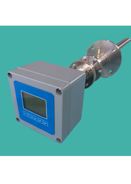
Doppler Flow Meter is a new type of non-contact ultrasonic flow meter. Installs completely outside the pipe, eliminating the need to stop flow and cut the pipe. Doppler Flow Meter is based on the working principle of Doppler ultrasound, using advanced frequency difference method to process the signal. It has the function of adjusting the ultrasonic transmission power. Easily solve application problems that cannot be solved by ordinary flowmeters such as super-large pipe diameter, thick pipe wall, and cement lining.

Doppler Flow Meter

Briefly introduce Doppler flow meters

A Doppler flow meter is a high-tech device born out of our quest for advanced flow measurement solutions. This ultrasonic flow meter measures volumetric flow through a pipe by employing the Doppler Effect – a principle that’s been under scientific scrutiny for centuries.

Johann Christian Doppler, an Austrian physicist, was the first to propose the Doppler Effect in 1842. This phenomenon observed in sound, light, and radio waves opened a myriad of possibilities, one of which was the inception of the Doppler flow meter.

The Doppler flow meter emerged in the latter half of the 20th century, as industries around the globe grappled with the challenges of monitoring ‘dirty’ liquids full of particles or bubbles. Traditional flow meters fell short in these scenarios, creating a dire need for a solution that could accurately measure such flows.

Enter the Doppler flow meter. Its unique non-invasive approach, where it clamps onto the outside of a pipe, disrupted traditional flow measurement norms. This innovation enabled accurate measurement of previously tricky ‘dirty’ liquids without disturbing the flow, thereby overcoming a significant industrial hurdle.

Fast forward to today, the Doppler flow meter is a staple in various industries such as wastewater management, pulp and paper, food and beverage production, and many more. Its ability to seamlessly integrate into these diverse industrial scenarios stands as a testament to its adaptability and precision, reinforcing its integral role in modern flow measurement.

How Does a Doppler Flow Meter Work?

he Doppler flowmeter has the capability to translate a detected frequency shift into an evaluation of volumetric flow rate. This process involves determining the flow velocity within a conduit by examining the frequency shift, the original frequency of the ultrasonic signal, the speed of sound through the transmitter material, and the sine of the angle at which the signal is introduced to the fluid. Once the velocity has been established, the volumetric flow rate can be simply calculated by multiplying this velocity by the conduit’s cross-sectional area.

In measuring the flow rate, the meter primarily focuses on the velocity at the points of discontinuity rather than the velocity of the fluid itself. The velocity of flow (V) can be deduced using the given equation:

V = (f0 – f1)Ct / 2f0 cos(a)

Here, Ct stands for the speed of sound within the transducer, f0 denotes the transmission frequency, f1 refers to the reflection frequency, and a represents the angle between the transmitter and receiver crystals in relation to the tube axis. Given that Ct / 2f0 cos(a) is a constant (K), this equation can be simplified to:

V = (f0 – f1)K

Hence, the flow rate V (ft/sec) is directly proportional to the frequency change. The flow rate (Q in gpm) inside a pipe with a specific internal diameter (ID in inches) can be calculated by the subsequent equation:

Q = 2.45V(ID)^2 = 2.45(f0 -f1)K^2

The existence of acoustic discontinuities is pivotal to the functioning of a Doppler flow meter. It’s generally accepted that, for adequate signal reflection, the concentration of solid particles should be at least 80-100 mg/l, with particles being +200 mesh (+75 microns) in size. For bubbles, a diameter between +75 and +150 microns at a concentration of 100-200 mg/l is ideal. Any changes in the size or concentration of the discontinuity may shift the amplitude of the reflected signal, thus inducing errors.

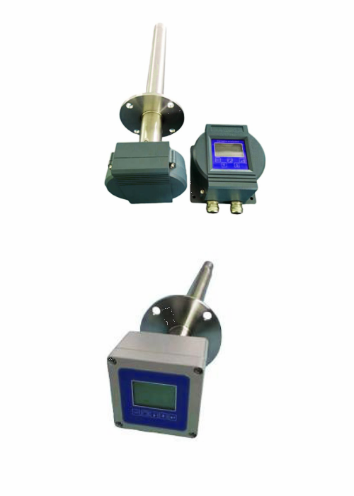
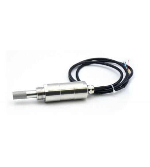
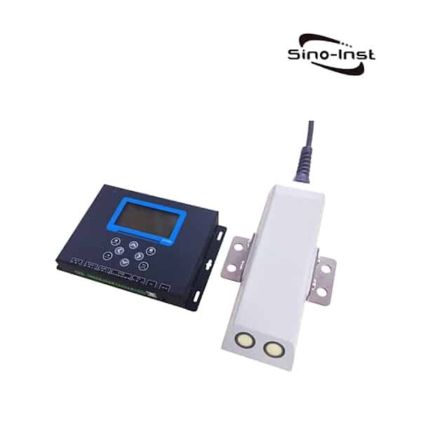
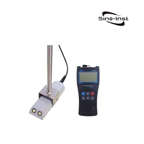
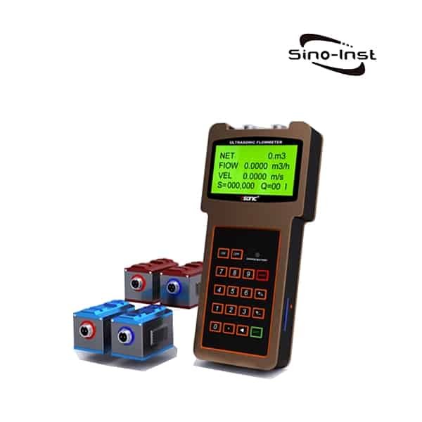
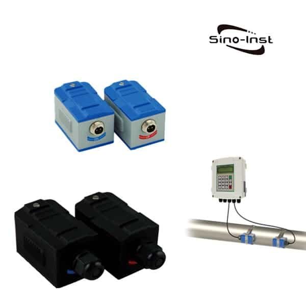
Doppler flowmeters can feature either one or two sensors. Regardless of the type, both contain a transmitter and a receiver; in a single sensor Doppler flowmeter, both are housed within a single unit. The transmitted signal is reflected back to the receiver by particles within the fluid. In a dual sensor flow meter, the transmitter and receiver are placed on opposite sides of the pipe.

Doppler flow meters can be an excellent choice for monitoring purposes, given their non-intrusive nature and low-maintenance requirements. They offer swift and accurate flow measurements for a broad spectrum of liquids across various temperature and flow conditions. However, it’s crucial to note that the fluid being measured must contain air bubbles or particles for the meter to function correctly. Also, the use of lined or stainless steel piping could obstruct the transmitter signal, thereby diminishing measurement accuracy.

Unique Technical Advantages of Doppler Flow Meter

The Doppler Flow Meter offers unique technical advantages, as translated and expanded upon below:

  1. It is capable of measuring both turbid and pure liquids, essentially functioning as both a high-precision Doppler ultrasonic flow meter and a high-precision transit-time ultrasonic flow meter.
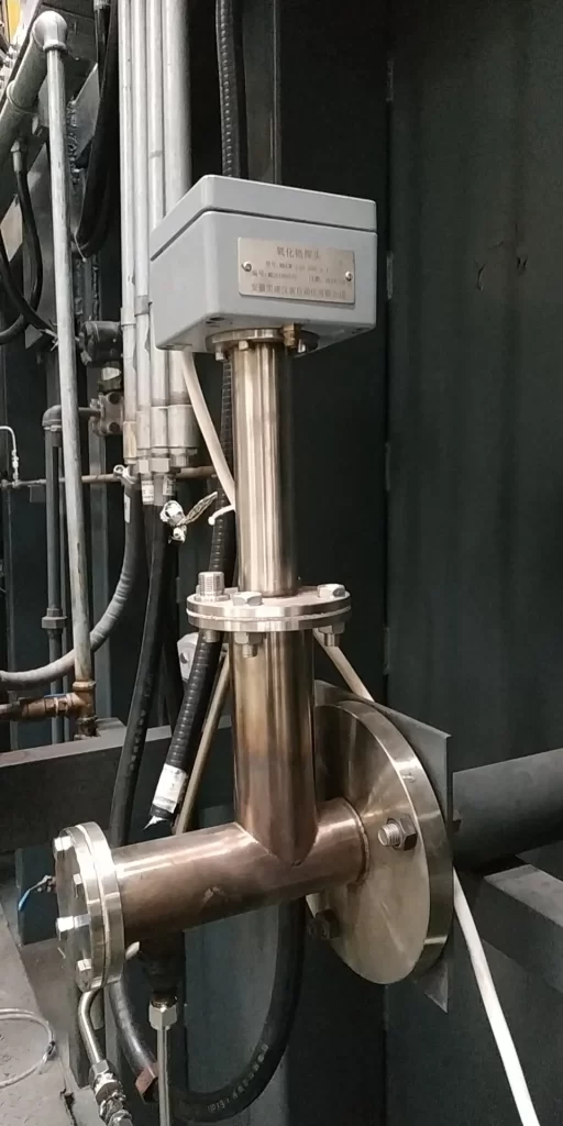
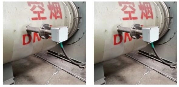
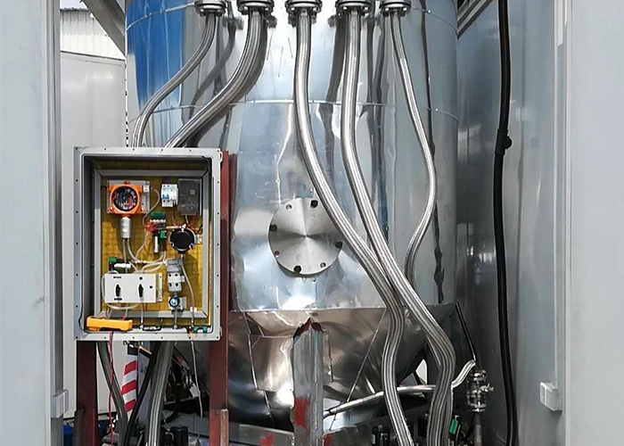
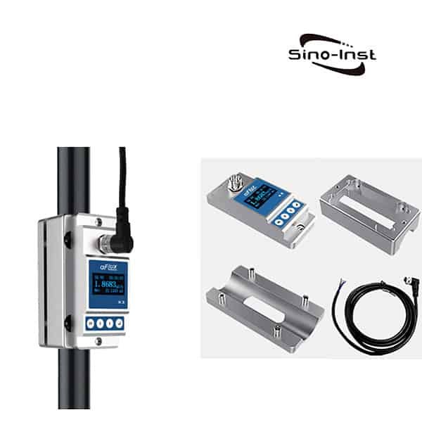
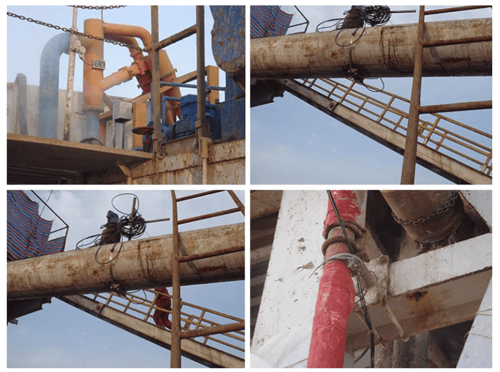
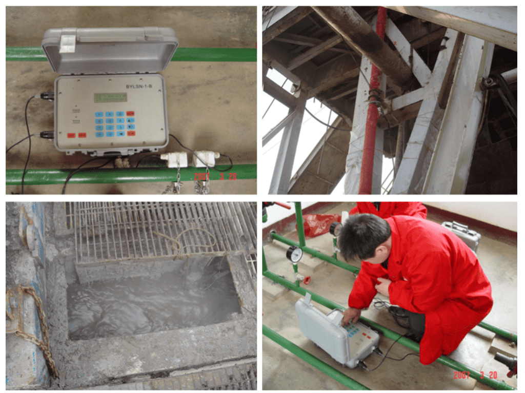
  2. It employs a non-contact measurement approach, with an externally clamped installation method. This means that there’s no need to halt flow or cut pipelines during setup, resulting in significant time and cost savings.
  3. It has a robust resistance to interference from variable frequency drives, ensuring accurate and stable measurements even in environments with electrical noise.
  4. It is highly effective in resolving application issues that other ultrasonic flow meters cannot, such as those involving large pipe diameters, thick pipe walls, and cement linings. This makes it a versatile solution for a range of challenging flow measurement situations.
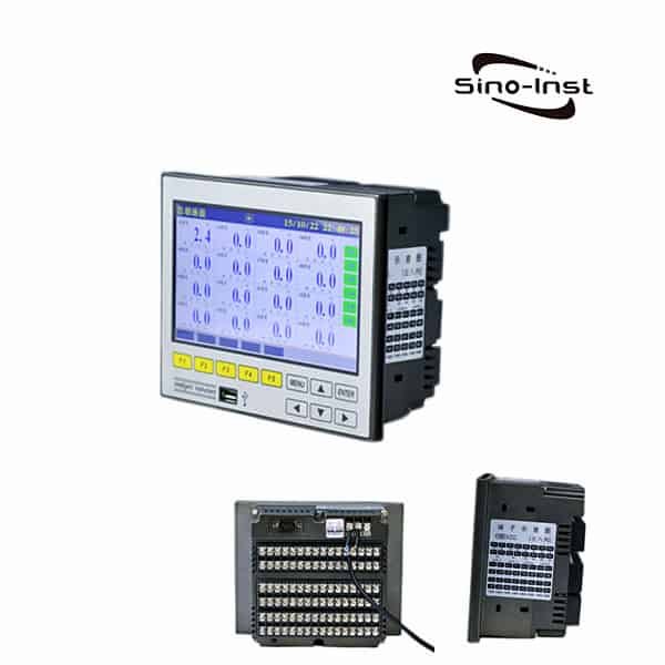
  5. It features a built-in data logging function, capable of recording up to 10 files, each containing 65,072 data points. This extensive data storage capacity allows for comprehensive tracking and analysis of flow rates over time.
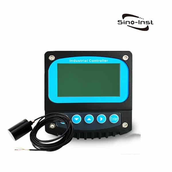
  6. It also offers data replay capabilities. The flow meter comes with dedicated software featuring a Microsoft Windows-style graphical interface. Via the RS-232 interface, data can be downloaded to a computer for detailed analysis. The software visually displays instant flow rate-time curve waveforms, which can be scaled arbitrarily along the time axis. This provides a powerful tool for managers to analyze data.
  7. The flow meter has an inbuilt calibration function, providing a quick and convenient operation process. This promotes consistent accuracy and reliability in measurements.
  8. It is equipped with yearly, monthly, and daily flow accumulation functions. It can log cumulative flow for the past five years and the current year, the past 12 months and the current month, and the past 31 days and the current day. This data provides a comprehensive view of flow patterns and trends, aiding in forecasting and decision-making processes.

Typical application of Doppler Flow Meter

The Doppler Flow Meter finds its primary application in an array of settings, notably in the measurement and management of various types of fluids. Some typical applications are outlined below:

  1. Wastewater: The Doppler Flow Meter is highly effective in measuring the flow rate of wastewater, a crucial parameter in wastewater treatment and management.
  2. Raw Water: Raw water, including surface and groundwater before treatment, requires flow rate monitoring for efficient water supply management. Doppler Flow Meters can accurately measure this.
  3. Recirculated Water: In many industrial processes, water is recirculated for cooling or other purposes. Here, Doppler Flow Meters can ensure that the recirculation process is functioning efficiently.
  4. Pulp and Slurry: The flow rate of pulp in paper manufacturing or slurry in mining is difficult to measure due to its high solid content. However, the Doppler Flow Meter can handle this challenge effectively.
  5. Crude Oil: In petroleum production and transportation, accurate flow rate measurement is crucial. Doppler Flow Meters are highly effective in such environments.
  6. Acidic or Alkaline Liquids, Chemical Raw Materials: In the chemical industry, flow rate measurement of corrosive liquids and other chemical raw materials is crucial. The non-contact nature of Doppler Flow Meters makes them an excellent choice for these applications.
  7. Seawater: Whether in desalination plants or marine research, accurate flow rate measurement of seawater is needed. Doppler Flow Meters are up to the task.

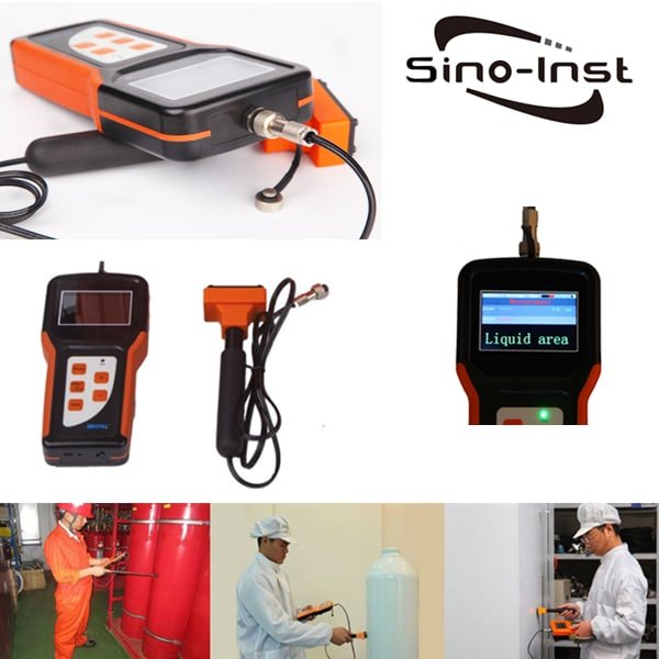
Additionally, Doppler Flow Meters are useful in field flow verification. They can be used on-site to calibrate and verify the performance of other flow meters, ensuring the accuracy of flow measurements across various instruments.

FAQ

Think of a Doppler flow meter as a futuristic traffic officer of sorts. It measures the flow rate of fluid within a pipe, all without stepping a foot inside! This remarkable device utilizes a fascinating principle known as the Doppler effect to perform its duty, proving itself as an invaluable asset in various industries.

Yes, they certainly are! Doppler flow meters can provide precise and swift measurements. They’re like speedy math whizzes, rapidly calculating velocity and flow rate. But remember, they require some form of ‘discontinuity’ in the fluid – think solid particles or air bubbles – to work accurately. Without these, their effectiveness could diminish. So, it’s vital to ensure the fluid has enough of these elements for the meter to operate effectively.

Doppler flow meters have a special place in the world of medicine. These nifty devices help medical professionals in assessing blood flow in patients’ bodies. This is crucial in identifying any blockages or abnormalities that could cause health issues. By providing quick and precise readings, Doppler flow meters can make a real difference in patient care.

Doppler flow operates using the principles of the Doppler effect. The Doppler flow meter sends ultrasonic signals into the moving fluid and reads the frequency shift of the signals bouncing back. This shift in frequency allows the meter to calculate the velocity of the fluid, which it then multiplies by the area of the pipe to determine the volumetric flow rate. It’s like bouncing a ball off a moving car and calculating the car’s speed from how quickly the ball returns. It’s pretty neat when you think about it!

More Ultrasonic Measurement Solutions

Extended reading:

Ultrasonic flow measurement

Ultrasonic flow meters, using the ultrasonic principle, measure the velocity of flow. We can use a different type of ultrasonic…

Embarking on a journey through Doppler flow meters, we’ve uncovered their scientific operation, utility, and accuracy. These devices offer speed, precision, and convenience to flow measurement, proving indispensable across industries.

At Sino-Inst, our expertise transcends understanding these tools. As experienced manufacturers and suppliers, we deliver tailored solutions for your specific needs. Need a Doppler flow meter for your operations? Our team stands ready to guide you towards the perfect fit for optimal performance.

Simplify your flow measurement tasks with us. Reach out today for high-quality, custom Doppler flow meters. Let Sino-Inst be your partner in achieving flow measurement success.

Request a Quote

Please enable JavaScript in your browser to submit the form

What Is Zirconia Oxygen Sensor?

Welcome to the world of Zirconia Oxygen Sensors, a cornerstone of precision in process control and industrial efficiency. Oxygen plays a pivotal role in numerous industrial processes, making its precise monitoring critical. That’s where our focus, the zirconia oxygen sensor, enters the scene.

What is zirconia oxygen sensor?

A zirconia oxygen sensor, also known as a zirconium dioxide oxygen sensor, is a type of sensor that measures oxygen levels, often used in automotive and industrial applications.

Its key differentiator? It relies on the unique properties of zirconia, or zirconium dioxide, a solid-state material known for its conductive abilities. But, let’s not get ahead of ourselves. By the end of this comprehensive guide, you’ll not only know how these sensors work but also appreciate their value in your operations.

Why zirconia oxygen sensor is important ?

In 1889, Nernst discovered the ionic conduction phenomenon of stabilized zirconia at high temperature. Since then, zirconia has become the most common solid electrolyte for research and development, and it has been widely used in high-temperature technology, especially high-temperature testing technology.

Compared with the existing oxygen measuring instruments (paramagnetic oxygen analyzer, electrochemical oxygen analyzer, etc.), the oxygen probe has simple structure, short response time (0.1s~0.2s), wide measurement range (from ppm to hundred content), high operating temperature (600°C ~ 1200°C), reliable operation, convenient installation, and small maintenance. Therefore, it is widely used in metallurgy, chemical industry, electric power, ceramics, automobiles, environmental protection and other industrial sectors.

In the kiln combustion process, when the air excess coefficient is too small, that is, the oxygen content is insufficient, the thermal efficiency decreases and black smoke is caused by the increase of incomplete combustion loss; when the oxygen content is too large, and due to the large exhaust smoke loss, SO2 And the amount of NOX increases. It will also lead to low thermal efficiency and environmental pollution.

Therefore, the use of the oxygen analyzer can automatically and continuously monitor the oxygen content in various furnace flue gases. To control the precise air-fuel ratio and achieve economical combustion, can obtain accurate thermal efficiency and reduce environmental pollution.

Oxygen analyzers do more than provide useful parameters for operators to adjust the air/fuel ratio. It can realize the automation of thermal control and achieve the purpose of energy saving and production increase.

The oxygen sensor, the core component of the oxygen analyzer, is made of stable zirconia material, and the melting point of the material is above 2200°C. It has good performance of high temperature resistance and corrosion resistance. Zirconia flue gas oxygen analyzer can adapt to high temperature, large dust and corrosive environment. It is unmatched by other methods, and it is the preferred instrument generally adopted by various countries in recent decades.

The Science Behind Zirconia Oxygen Sensors

1. Detection sensor

In this system, the detector is the most important working part. It directly affects the performance and life of the whole system.

Among them, the zirconium tube assembly is the main working device. It is the key to convert changes in oxygen concentration into changes in electrical signals.

The principle of oxygen measurement is as follows. The zirconium tube is mixed with yttrium oxide or calcium oxide in pure zirconium oxide. Stabilized zirconia sintered at high temperature, it is a solid electrolyte, generally made into a tube.

It is a good conductor of oxygen ions under high temperature conditions above 600°C.

Porous platinum (Pt) electrodes are sintered on both sides of the zirconia electrolyte (ZrO2 tube).

At a certain temperature, when the oxygen concentration on both sides of the electrolyte is different, the oxygen molecules on the high concentration side (air) are adsorbed on the platinum electrode and combine with electrons (4e) to form oxygen ions O2-. Make this electrode positively charged.

O2- ions migrate to the Pt electrode on the low oxygen concentration side through the oxygen ion vacancies in the electrolyte to release electrons and convert them into oxygen molecules, making the electrode negatively charged.

The zirconia tube becomes an oxygen concentration battery.

The following reaction will take place at the two platinum electrodes:

On the air side (reference side) electrode: O2+4e → 2O2-
On the hypoxic side (measured side) electrode: 2O2-→ O2+4e

That is, one oxygen molecule in the air captures four electrons on the electrode and becomes two oxygen ions. Oxygen ions migrate through zirconia to the low-oxygen side electrode driven by the potential difference in oxygen concentration. Four electrons are left to the electrode to recombine into oxygen molecules. When the battery is in equilibrium, the potential value E between the two electrodes remains constant.

Its potential value E conforms to the Nernst equation:

In the formula:
R——gas constant
T——absolute temperature
F – Faraday constant
Px——the percentage of oxygen concentration in the measured gas
Pa – the percentage of oxygen concentration in the reference gas, generally 20.60%;

In this way, if the oxygen cell is heated to a specified temperature, the measured gas and the reference gas flow through the two sides of the zirconium tube respectively, and the potential generated has a certain relationship with their concentrations. If the concentration of the reference gas is known, it is easy to determine the oxygen concentration of the measured gas.

The detector uses this principle to provide the conditions for the normal operation of the zirconium tube to achieve practical purposes.

2. Transmitter

The function of the oxygen transmitter is to convert the oxygen potential signal and temperature signal of the detector into oxygen content according to the Nernst formula, and to control the working temperature of the zirconium tube.
Summarized into temperature measurement, temperature control, oxygen conversion, output and other functions. Different kinds of transmitters are functionally identical.

Harnessing Zirconia’s Power: Industrial Applications

Industries worldwide have recognized the value of zirconia oxygen sensors. From combustion control in power plants to maintaining the optimal environment in kilns, zirconia oxygen sensors are instrumental in ensuring operations run smoothly and efficiently.

Let’s dive into some specific industrial applications where these sensors excel.

  1. Power Plants: Power plants, particularly those burning fossil fuels, need to closely monitor and control combustion processes to maximize efficiency and minimize emissions. Here, zirconia oxygen sensors offer an accurate and durable solution.
  2. Automotive Industry: Car engines use zirconia oxygen sensors (often located in the exhaust pipe) to measure the amount of oxygen in the exhaust gas. This data is crucial for the engine control unit (ECU) to adjust the air-fuel mixture and optimize engine performance.
  3. Food and Beverage Industry: In food packaging, zirconia oxygen sensors are used to monitor oxygen levels and ensure the longevity and quality of the product.

Our Recommended Zirconia Oxygen Sensors

DisplayLCD menu operation
Instrument accuracy1%
Temperature control accuracy±1℃
output4-20mA
power supply220V+10%
power<150W
Range0-25% (programmable)
Flue gas temperature0-700℃
Flue gas pressure-20KPa~+20KPa
Protection tube material316L stainless steel protection tube
SpecificationΦ45mm
Transmitter materialcast aluminum
degree of protectionIP65
flangeOuter diameter 155mm hole distance 130mm (other specifications are optional)
Furnace resistance valueStandard 60Ω (optional 80Ω, 120Ω, 160Ω)
service life15 years (according to actual working conditions)
Probe length500mm, 800mm, 1000mm, 1200m (other specifications can be customized)

Selection of Zirconia Oxygen Analyzer/zirconia oxygen sensor

Low temperature type is selected when the flue gas temperature is below 400°C;
When the flue gas temperature is below 700°C, select the warm type;
Choose the high temperature type when the temperature is above 700°C.
If the flue gas contains more corrosive gases, an aspirating oxygen analyzer with a sample gas pretreatment device should be selected.

The total length of the probe refers to the length from the installation flange to the sampling port of the oxygen sensor. The actual total length of the probe will also add 150mm to the length of the junction box.
Probe length = mounting screw distance 100mm + furnace wall thickness + length inserted into the furnace or flue (generally around 400mm)

Oxygen converters can be divided into disc meters and wall meters according to the installation form. Disc watches include a disc vertical watch and a disc horizontal watch.
The installation position of the wall-mounted meter can be selected at a place close to the oxygen detector and convenient for debugging.

There are four options for the oxygen content of the full scale of the transmitter: 0~5%, 0~10%, 0~20.6% (factory default value), 0~25%. Corresponding to the current output 4 ~ 20mA.

More Gas Measurement Solutions

Digital air flow meters

What Is Digital Air Flow Meters? The digital air flow meter is also a digital gas flow meter. The digital…

Industrial CO2 flow meters

CO2 flow meters are instruments that can measure the flow of gaseous or liquid carbon dioxide. CO2 is a common…

Industrial Oxygen Flow Meters

Oxygen Flow Meters are digital flow meters that can measure industrial oxygen. It is very important to choose a suitable…

As a seasoned manufacturer and supplier, we take pride in offering a broad range of top-tier zirconia oxygen sensors. However, we understand that every business is unique. That’s why we go above and beyond to provide customized solutions, specifically tailored to your distinct operational needs.

At Sino-Inst, we’re not just providers; we’re partners in your operational success. With our high-quality, customizable zirconia oxygen sensors, you gain accuracy, reliability, and the edge you need in your industry. Our experienced team is ready to help tailor solutions that fit your specific needs. Elevate your operations with us— reach out to Sino-Inst today. Choose excellence. Choose partnership. Choose Sino-Inst.

Request a Quote

Please enable JavaScript in your browser to submit the form

Integrated Zirconia Oxygen Analyzer

Zirconia Oxygen Analyzer is an analyzer used to monitor and control the oxygen concentration of flue gas in combustion gases, boilers and industrial furnaces. Widely used in industrial fields that require a lot of energy – such as steel plants, power plants, petroleum and petrochemical, ceramics, paper, food or textile industries, as well as various incinerators and medium/small boilers, etc. Zirconia Oxygen Analyzer helps save energy. It can also reduce CO2, SOx, and NOx emissions by controlling complete combustion. Contribute to the protection of the earth’s environment, prevention of global warming and air pollution.

Integrated Zirconia Oxygen Analyzer Features

  • Aluminum die-casting junction box, IP65 protection level, exquisite appearance.
  • The filter adopts a circular sheet shape, which reduces the direct erosion of flue gas and prolongs the service life.
  • At the same time, there is no need to consider the directionality.

Technical Specifications

DisplayLCD menu operation
Instrument accuracy1%
Temperature control accuracy±1℃
output4-20mA
power supply220V+10%
power<150W
Range0-25% (programmable)
Flue gas temperature0-700℃
Flue gas pressure-20KPa~+20KPa
Protection tube material316L stainless steel protection tube
SpecificationΦ45mm
Transmitter materialcast aluminum
degree of protectionIP65
flangeOuter diameter 155mm hole distance 130mm (other specifications are optional)
Furnace resistance valueStandard 60Ω (optional 80Ω, 120Ω, 160Ω)
service life15 years (according to actual working conditions)
Probe length500mm, 800mm, 1000mm, 1200m (other specifications can be customized)

Frequently Asked Questions

Zirconia oxygen analysis is a method of measuring the oxygen content in a gas sample. The technology is based on the fact that zirconium dioxide, or zirconia, is an oxygen ion conductor at high temperatures. When a voltage is applied across a zirconia cell, it drives oxygen ions from one side to the other, creating a current proportional to the oxygen concentration in the gas sample. This technology is widely used in a variety of industries, including combustion control systems, car emission controls, and environmental monitoring.

A zirconia oxygen analyzer usually operates at a high temperature, typically around 700 to 800 degrees Celsius. At these elevated temperatures, zirconia becomes a good conductor of oxygen ions. This high temperature is crucial for the operation of the device, as it facilitates the necessary electrochemical reactions that allow oxygen ions to move across the zirconia membrane, generating an electrical signal proportional to the concentration of oxygen.

The operation of a zirconia oxygen analyzer is based on the Nernst equation. This equation expresses the relationship between the voltage generated across a zirconia cell and the oxygen concentrations on each side of the cell. Here it is in its simplest form:

E = E0 + RT/4F * ln(pO2(1)/pO2(2))

Where:

E is the voltage across the cell,
E0 is the standard cell potential,
R is the gas constant,
T is the temperature in Kelvin,
F is Faraday’s constant,
pO2(1) and pO2(2) are the partial pressures of oxygen on the two sides of the cell.

Zirconia and titania O2 sensors both serve the same purpose of measuring oxygen levels, but they operate using different principles and have different characteristics:

Zirconia sensors rely on the Nernst effect, which creates a voltage difference proportional to the logarithm of the oxygen pressure difference across a zirconia cell. Zirconia sensors are excellent at providing accurate and reliable measurements and are commonly used in automobile exhaust systems and industrial applications.

Titania sensors, on the other hand, change their electrical resistance according to the concentration of oxygen. When exposed to a rich mixture (more fuel, less oxygen), the resistance of the titania sensor increases; when exposed to a lean mixture (less fuel, more oxygen), the resistance decreases. This type of sensor is simpler and more robust but provides less precise measurements compared to zirconia sensors.

Standard gas:

National secondary standard material, oxygen in nitrogen. Oxygen content is proportioned according to need. The general standard is 5.0%. Calibrate zirconia oxygen analyzers against known gas standards. Turn on the calibration gas, connect the calibration gas connection hose to the calibration gas inlet of the zirconia probe, and judge whether the zirconia oxygen analyzer is accurate according to the known oxygen content of the calibration gas.

Selection of Zirconia Oxygen Analyzer

1) The flue gas temperature at the recommended installation sampling point

Low temperature type is selected when the flue gas temperature is below 400°C;
When the flue gas temperature is below 700°C, select the warm type;
Choose the high temperature type when the temperature is above 700°C.
If the flue gas contains more corrosive gases, an aspirating oxygen analyzer with a sample gas pretreatment device should be selected.

2) Select the probe length

The total length of the probe refers to the length from the installation flange to the sampling port of the oxygen sensor. The actual total length of the probe should also add 150mm to the length of the junction box.

Probe length = mounting screw distance 100mm + furnace wall thickness + length inserted into the furnace or flue (generally around 400mm)

3) Instrument selection

Oxygen converters can be divided into disc meters and wall-mounted meters according to the installation form. The disc meters include disc vertical meters and disc horizontal meters. The installation position of the wall-mounted meter can be selected at a place close to the oxygen detector and convenient for debugging.

There are four options for the oxygen content of the full scale of the transmitter: 0~5%, 0~10%, 0~20.6% (factory default value), 0~25%, corresponding to the current output of 4~20mA.

More Gas Measurement Solutions

Introducing our Integrated Zirconia Oxygen Analyzer, a cutting-edge tool designed to measure oxygen levels accurately. This device utilizes zirconia’s unique properties to give precise readings in various environments, from car emissions control to environmental monitoring.

We, at Sino-Inst, are experienced manufacturers and suppliers in the field of Zirconia Oxygen Analyzers. We not only offer top-quality products but also provide customization to cater to your unique needs. With Sino-Inst, you get a reliable partner committed to your success.

Contact us today to discover how our Integrated Zirconia Oxygen Analyzer can enhance your operations.

Request a Quote

Please enable JavaScript in your browser to submit the form

Grain Bin Level Indicators: The Missing Piece in Your Grain Storage Solution

Grain Bin Level Indicators are transformative tools for modern agriculture. They give accurate, real-time measurements to prevent bins from being overfilled or underfilled.
Revolutionizing grain management, these devices facilitate accurate real-time grain bin measurements, mitigating the risk of overfilling or underfilling.
They’re the real game-changers in grain storage solutions. Perfect for maintaining optimal grain storage conditions, these indicators are truly the unsung heroes in grain storage solutions.

The Challenges of Grain Storage

Grain storage, especially in large-scale silos for processing, presents a number of challenges:

  • Maintaining Optimal Storage Conditions: This is crucial for preserving grain quality and preventing spoilage.
  • Monitoring Levels: Ensuring bins are neither overfilled nor underfilled is necessary to avoid waste and maintain operational efficiency.
  • Managing Large Quantities: Industrial silos often contain vast quantities of grain, making it difficult to monitor levels accurately.
  • Ensuring Safety: Overfilled or underfilled bins can lead to safety issues, like structural damage to the silos or poor grain circulation leading to spoilage.
  • Protecting Profits: All of these challenges, if not managed effectively, could lead to inefficiencies, increased costs, and reduced profits.

The Grain Bin Level Indicator offers a solution to these issues, helping to improve the grain storage and processing system.

Grain Bin Level Indicator: A Game-Changer in Grain Storage

The Grain Bin Level Indicator is a technological marvel in grain storage management. This device provides real-time level monitoring, sending alerts when the grain reaches a specified level. No more guesswork, no more wasting hours manually checking levels.

Not convinced yet? Let’s dig a little deeper into the workings and benefits of this amazing product.

Grain Bin Level Indicators, also known as level sensors, come in different varieties to suit various applications. Here’s an overview of some common types and their working principles:

These sensors work based on the principle of capacitance. They measure changes in an electrical field to determine the level of grain in the bin.

Rotary level indicators are mechanical devices that have a rotating paddle. When the paddle encounters resistance from the grain, it stops rotating. This stoppage triggers a signal that indicates the level of grain in the bin.

These sensors use sound waves to determine the level of grain. An ultrasonic pulse is emitted from the sensor, which then waits for the pulse to bounce back after hitting the surface of the grain. The time it takes for the pulse to return helps determine the level of grain in the bin.

Similar to ultrasonic sensors, radar level sensors also use wave technology. However, instead of sound waves, they utilize radio waves, which can be more accurate in certain conditions.

These sensors vibrate at a certain frequency when there’s no grain present. When grain reaches the level of the sensor and dampens its vibration, it sends a signal indicating the grain level.

Type of SensorWorking PrincipleAdvantagesLimitations
Capacitance Level SensorsMeasures changes in an electrical field to determine grain levelReliable and accurate, suited to a variety of grainsMay require calibration for different types of grain
Rotary Level IndicatorsUses a rotating paddle that, when obstructed by grain, stops and sends a level signalSimple and cost-effectiveMechanical parts may wear out over time
Ultrasonic Level SensorsUses sound waves; the time for a pulse to bounce back indicates the grain levelAccurate, no moving parts, suitable for large binsCan be affected by dust and other atmospheric conditions
Radar Level SensorsUses radio waves; like ultrasonic sensors, measures the time for a pulse to returnVery accurate, not as affected by atmospheric conditions as ultrasonic sensorsCan be more expensive than other options
Vibrating Rod Level SensorsVibrates at a certain frequency; when grain dampens the vibration, it sends a level signalReliable and accurate, simple to install and useMay not be suitable for extremely light or fluffy grains

It’s important to note that different types of grain bin level indicators are suited to different applications and types of grains. Choosing the right one depends on your specific needs and circumstances. For more details about these indicators, their advantages, and how they can be integrated into your grain storage system, feel free to contact our team at Sino-Inst.

Unveiling the Power of Grain Bin Level Indicators

To appreciate the power of grain bin level indicators, consider this: A study by Purdue University revealed that grain spoilage and mishandling account for over $2.5 billion in losses annually in the US alone. This is where grain bin level indicators can make a real difference.

By providing accurate, real-time level data, these devices can prevent overfilling, reduce spoilage, and ultimately increase profitability. Moreover, grain bin level indicators are versatile, easy to install, and can be integrated into existing storage management systems.

Remote Level monitoring

It is necessary to realize the remote transmission display of the granary material level. There are three possible ways.

  1. Add a split monitor. General level meter as for a local display. But a monitor can be added if desired. Level meter mounted on top of tank with local display. A second display is mounted on the bottom of the tank. It is convenient for the staff to check the level and debug.
  2. Signal output. A general level meter can support 4-20mA or RS485 signal output. The output signal can be wired to the control room. Monitoring software for connection to PLC, DCS or user.
  3. Wireless IoT. With the addition of accessories such as a wireless gateway, the level meter can output the level signal through a wireless signal for a long distance. Such as GPRS, 4G, LoRA, etc.

FAQ

The Saf T fill grain bin level indicator is a popular model of level indicators designed for grain bins. It offers a simple, reliable way to prevent overfilling of grain bins.

Traditionally, grains in a grain bin are measured using a manual method known as ‘taping’. However, this method can be inaccurate and time-consuming. Modern methods include using devices like grain bin level indicators, which provide real-time, accurate measurements.

A bin level measuring system is a technology used to monitor and control the level of materials like grains in storage bins. These systems provide real-time data, helping to prevent overfilling or underfilling.

The number of bushels in a bin can be calculated using the bin’s diameter and height, and the type of grain stored. However, for more accurate measurements, devices like grain bin level indicators are recommended.

More Tank Level Measurement Solutions

In conclusion, grain bin level indicators are the missing piece in your grain storage solution. These devices, though small and simple, can revolutionize the way you manage your grain storage, saving you time, money, and unnecessary stress.

At Sino-Inst, we are a trusted manufacturer and supplier with years of experience in providing solutions to farming challenges. Our grain bin level indicators are customizable to suit your specific needs. Contact us today to discover how our products can transform your farming operations.

Request a Quote

Please enable JavaScript in your browser to submit the form

Gas Detection

Explore our wide range of gas detectors designed for numerous applications. We offer devices to detect individual gases like oxygen, carbon monoxide, and more, ensuring safety and efficiency. Choose from portable to fixed detectors or even multi-gas variants for diverse needs. We also provide alarm systems and water quality detectors. Simplify your safety and compliance needs with our easy-to-use, reliable instruments.

Gas Detection Products

More Detection and Analysis Sloutions

Request a Quote

Please enable JavaScript in your browser to submit the form

Voltage Pressure Transducer Comparison

Imagine being in a world where pressure measurements are a hassle. You’re constantly struggling with inaccurate readings, device malfunctions, and complicated setup processes. Sounds exhausting, right? Now enter voltage pressure transducers. These little devices are the unsung heroes of the industrial world, transforming your pressure measurement process from a frustrating chore into a smooth, reliable operation. Let’s dive in and learn more about these game-changing tools.

What is a Voltage Pressure Transducer?

A voltage pressure transducer is an electromechanical device that converts pressure into an analog voltage signal. This signal can be easily read and analyzed, making pressure monitoring a breeze. But how does it all work? Let’s find out.

More detailed guide about pressure transducers here:

The Inner Workings of Voltage Pressure Transducers

At the heart of every voltage pressure transducer is a sensing element, often a strain gauge or a piezoresistive sensor. When pressure is applied, this element deforms slightly. This deformation alters the electrical resistance of the sensor, and this change is converted into a voltage signal proportional to the applied pressure.

Voltage pressure transducers come in a variety of types, each suited to specific applications. Some popular types include strain-gauge pressure transducers, piezoresistive pressure transducers, and capacitive pressure transducers.

Why Voltage Output Signals?

Pressure changes can trigger variations in a sensor’s electrical resistance. In voltage output transducers, these changes convert into a voltage signal that matches the shift in pressure. These voltage signals usually fall within 0-5Vdc or 0-10Vdc, although the range can vary depending on the transducer and its application.

Voltage output signals, common in pressure and temperature sensors, are a type of analog output signal. There are many output options to choose from in this category. The most frequently seen ones in industrial settings are 1-5VDC, 1-6VDC, and 0-10VDC, particularly when power usage isn’t a main concern.

In our growing world of IoT and IIoT, sensors can now run on low power while using less current. This is a big win for remote equipment where replacing batteries often can be expensive and time-consuming.

In response to the demand for low power, various voltage output choices now run on 3V, 3.3V, 3.7V, 5V, and 9V power supplies and batteries. Some common signal pairings with these supply voltages include millivolt, 0.5-2.5VDC non-ratiometric, and 0.5-4.5VDC ratiometric outputs. The 0.5-2.5VDC output option is becoming more popular due to increased usage of 3 to 5VDC lithium-ion batteries.

While millivolt signals are ratiometric, 0.5-4.5VDC output, ratiometric to a regulated 5VDC excitation, is more commonly associated with the term “ratiometric.” This type of signal has gained popularity in automotive and off-road applications because it is proportional to the supply. For instance, a 10% drop in supply from the 5V source would result in a 10% decrease in the output signal. This type of signal continues to be used in similar applications and has also found use in industrial applications like compressors and water pumps.

Voltage Output Wiring Configurations

Voltage output pressure transducers typically come in two wiring configurations: three-wire and four-wire systems.

In a three-wire system, one wire is connected to the positive voltage supply, another to the output, and the third one to the ground. This setup is straightforward and commonly used.

The four-wire system, on the other hand, uses two wires for the supply voltage and two wires for the output. This configuration reduces errors due to voltage drop in the supply leads, providing more accurate readings, especially over longer distances.

Our Top Voltage Pressure Transducer Picks

Applications of Voltage Output Pressure Transducers

  1. Tank Level Monitoring: Paired with a SCADA system, these sensors are ideal for remotely monitoring fuel or water levels, especially in locations where conserving battery life is essential.
  2. Oil Field Equipment: In far-flung oilfields, these sensors help conserve battery life while providing ample signal strength for measuring and transmitting data to telemetry units and then to the cloud.
  3. Industrial Internet of Things (IIoT): Factories are increasingly adopting IoT technology to measure pressure and temperatures of various equipment, particularly where installing power sources is costly or difficult.
  4. HVAC and Refrigeration: For HVAC/R installations, these affordable, user-friendly sensors swiftly provide pressure, temperature, and combined readings, making them popular for use in confined spaces like boiler rooms.
  5. Automotive Systems: In vehicles, these sensors are crucial for monitoring systems like brakes and fuel, delivering real-time data for optimal operation.
  6. Aerospace and Aviation: These sensors offer real-time measurements in critical monitoring areas such as cabin pressure, engine oil pressure, and hydraulic systems, ensuring safe and efficient flights.

FAQ

A voltage pressure transducer is a device that converts pressure into a voltage signal, enabling easy monitoring and control of pressure.

The input voltage of a pressure transducer, also known as the excitation voltage, typically ranges from 5 to 36 volts DC, but it varies by model. Always refer to the manufacturer’s specifications.

To check the voltage on a pressure transducer, you’ll need a digital multimeter. Attach the multimeter’s probes to the transducer’s output wires and apply pressure. The multimeter should display the corresponding voltage.

A 4-20mA pressure transducer is a type of pressure transducer that outputs a current signal instead of a voltage signal. The 4-20mA signal is less susceptible to electrical noise, making it ideal for long-distance signal transmission.

Voltage output signals in pressure transducers play a crucial role in pressure monitoring and control. Understanding the workings of these signals and their appropriate applications can help you choose the right transducer for your specific needs.

Remember, at Sino-Inst, we offer a variety of voltage pressure transducers tailored to your requirements. Our experienced team is ready to assist you in finding the best pressure measurement solutions. Reach out to us today!

Request a Quote

Please enable JavaScript in your browser to submit the form