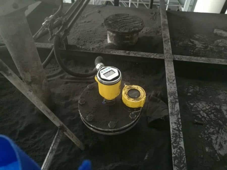
What is a Capacitive Level Sensor? Simply put, it’s a device used to accurately measure the level of materials in various industries. Unlike other types of sensors, capacitive level sensors use electrical properties to detect changes in the level of materials, making them non-contact and highly accurate.
In this article, we’ll dive into the world of capacitive level sensors, discussing how they work, where they’re used, their advantages and limitations, and what factors to consider when selecting one. If you’re new to capacitive level sensors, or just looking to learn more, this guide is the perfect place to start.

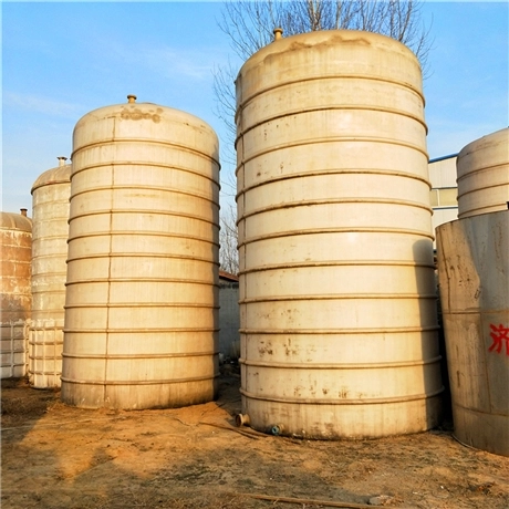
The purpose of a capacitive level sensor is to accurately and reliably measure the level of materials in various industrial applications.
Capacitive level sensor can measure the level of highly corrosive medium, high temperature medium and sealed container, regardless of the viscosity, density and working pressure of the medium.
Let’s first get to know the working principle of the capacitive level sensor.
capacitive level Measurement Principle
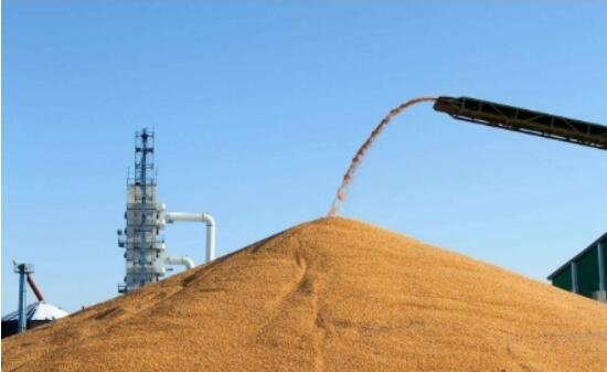
Have you ever wondered how we can measure the level of material in a tank? Well, that’s where the magic of capacitance level measurement comes in!
Think of a capacitor like two metal plates, with a thin layer of insulation in between. When the plates are close together, they can hold more electrical charge. In this measurement technique, the probe acts as one plate and the tank wall as the other. When the tank is empty, there’s plenty of space between the two plates, meaning they can hold very little charge. But as the material fills the tank, the plates move closer together and are able to hold more charge.
So, by measuring the electrical charge between the probe and the tank wall, we can determine just how full the tank is! It’s like a secret code between the sensor and the material in the tank, giving us the scoop on its contents.
Capacitance level measurement is a straightforward, dependable, and non-invasive way to keep track of what’s inside a tank. So the next time you’re curious about how much material is left, just remember the wonder of capacitance level measurement!
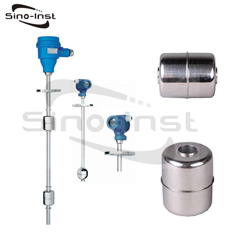
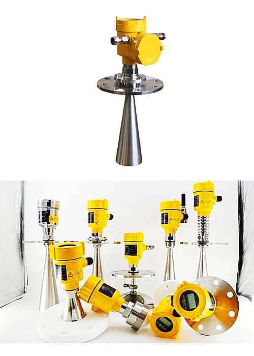
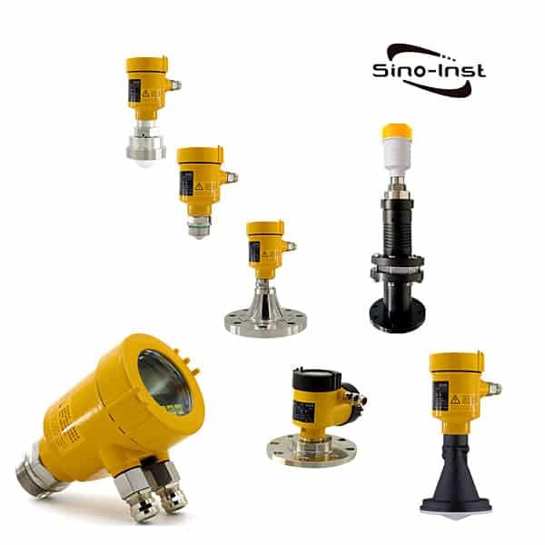
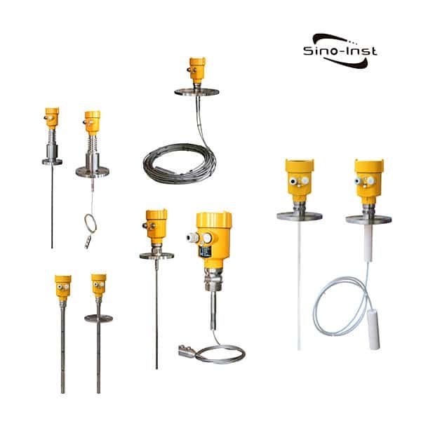
Different types of capacitive level sensors available in the market
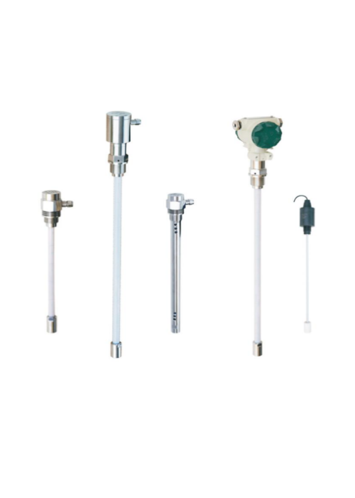
We have compiled a list of different types of capacity level sensors available in the market.


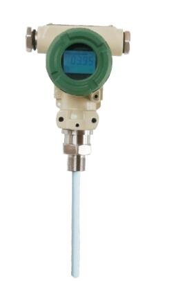


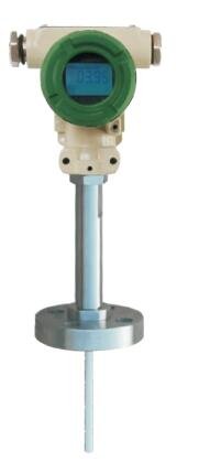


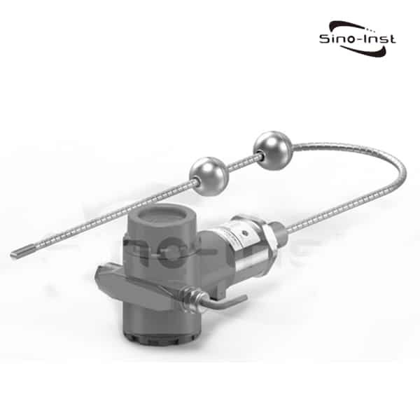
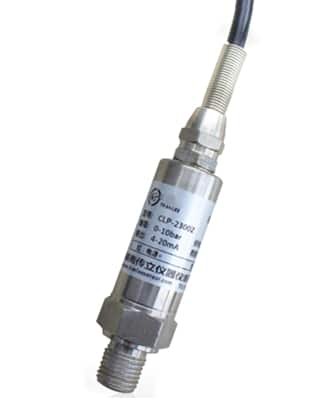
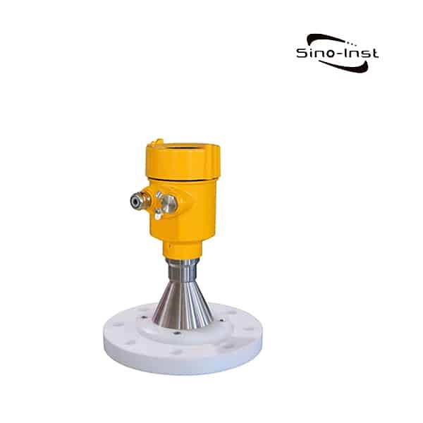
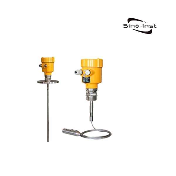
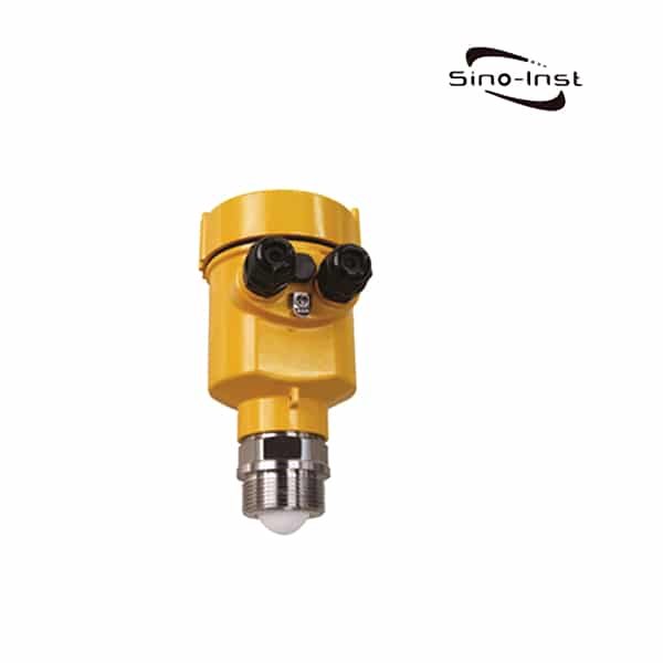
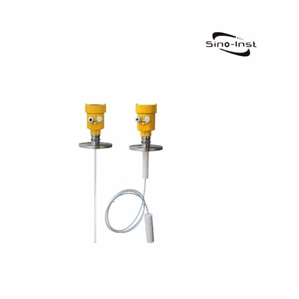
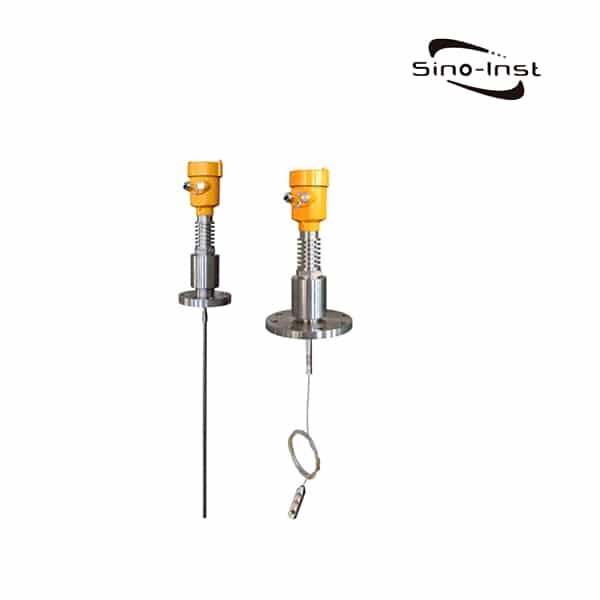
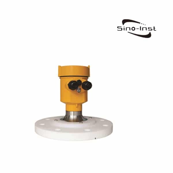
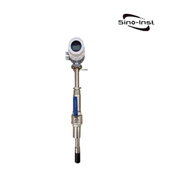
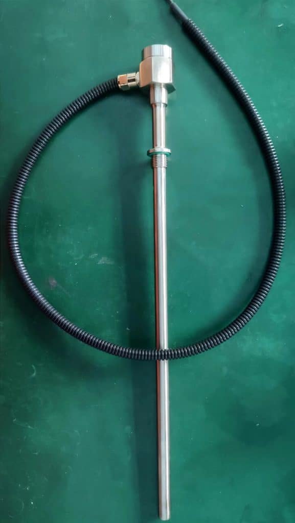
- Rod probe sensor – used for point-level sensing of liquids and solids.
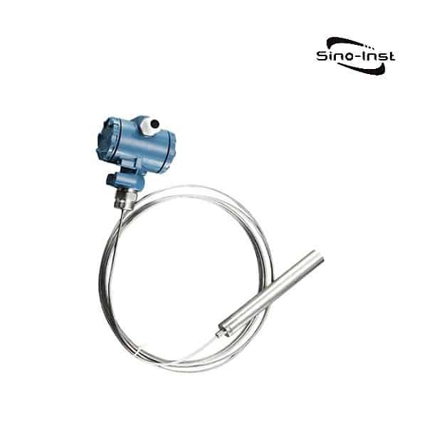
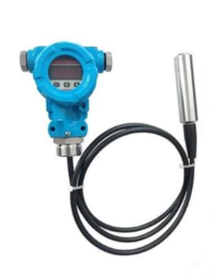
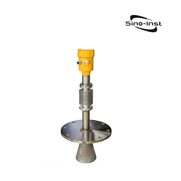
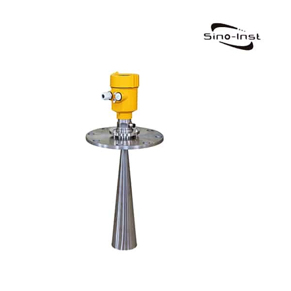
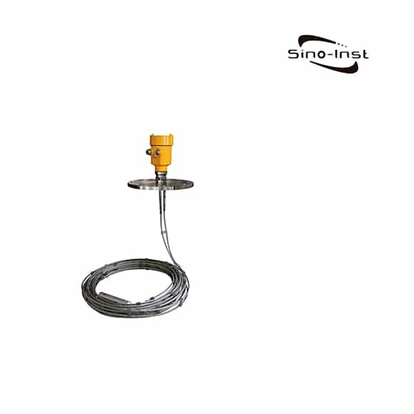
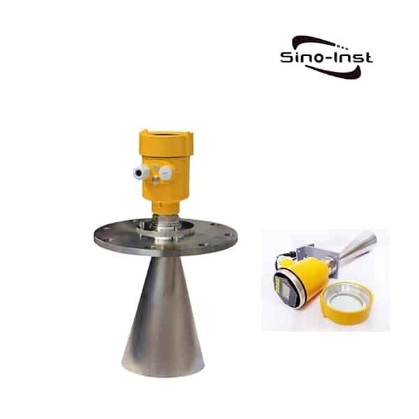
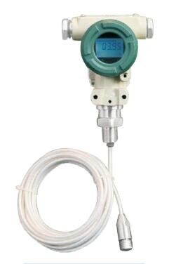
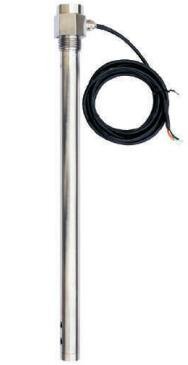
- Cable sensor – uses a cable to detect changes in the level of liquids or solids over a larger area.
- High-temperature sensor – designed for use in high-temperature applications such as chemical processing.
- Low-temperature sensor – Cryogenic Level Sensor for Liquid Nitrogen Tank Level Indicator
- Intrinsically safe sensor – designed for use in hazardous environments.
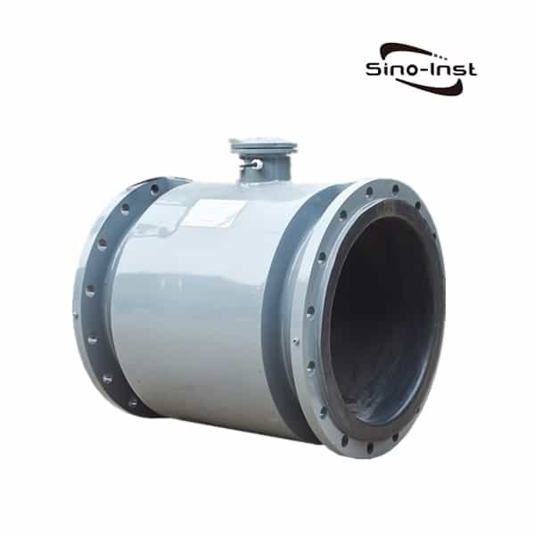
- Coaxial sheath type – suitable for measuring various non-conductive liquids
- Specialized capacitive sensors – designed for specific industries such as food and beverage.
Understanding the different types of capacitive level sensors available in the market is important for selecting the right sensor for your specific needs. Read more about: External Ultrasonic Tank Level Sensor Installation
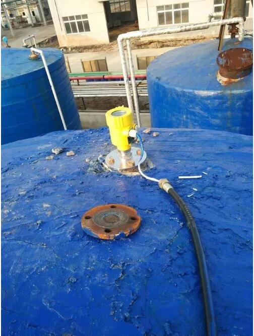
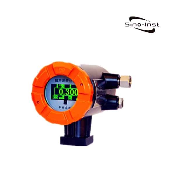
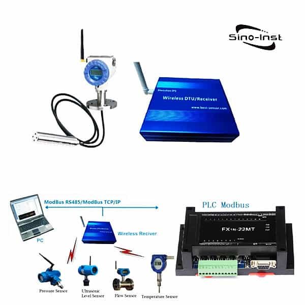
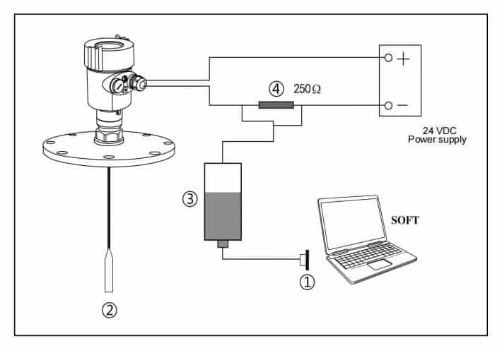
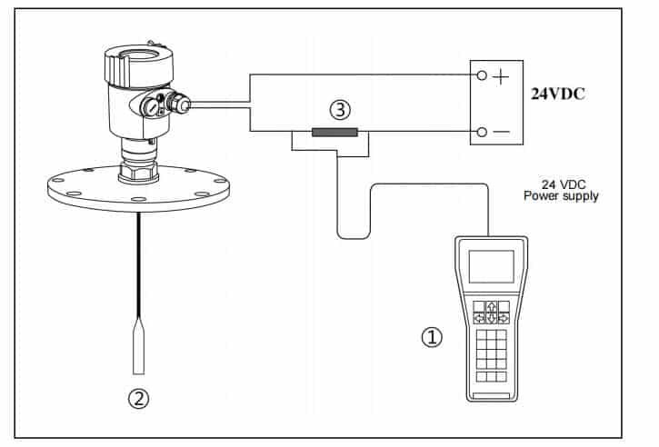
capacitive level measurement system
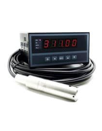
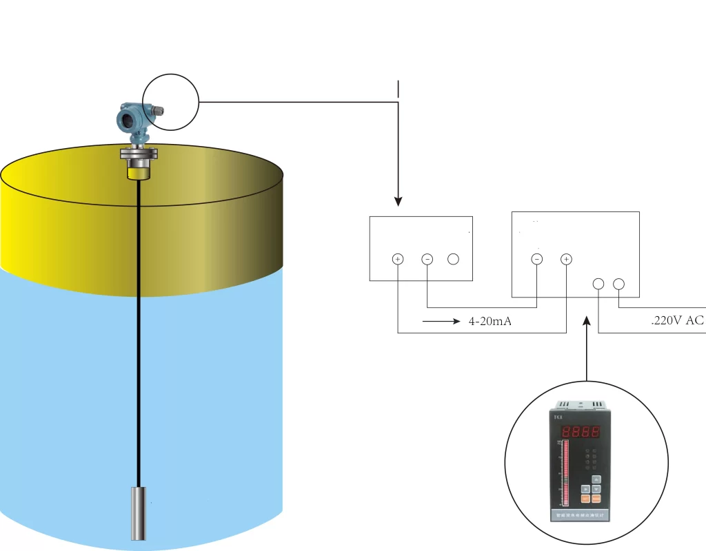
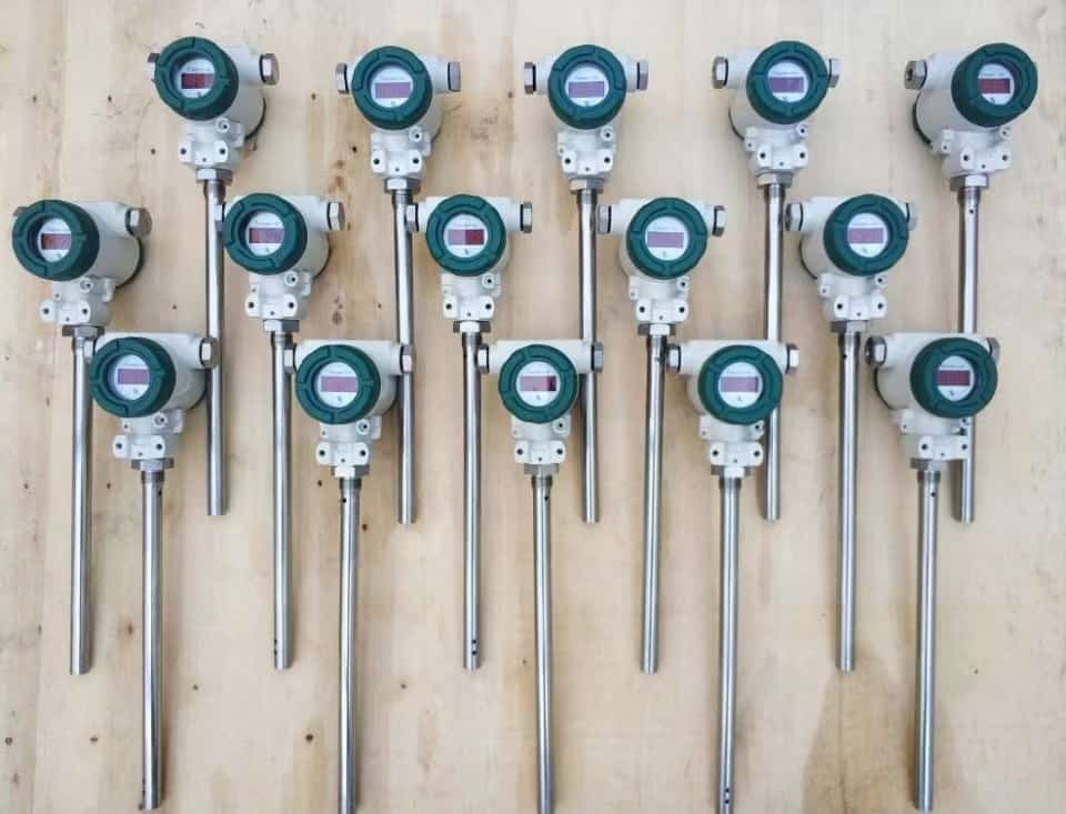
Capacitive level measurement systems are an exciting and innovative way to measure the level of liquids in containers. These systems are made up of two key components: capacitive level sensors and a liquid level recorder or volumetric recorder.
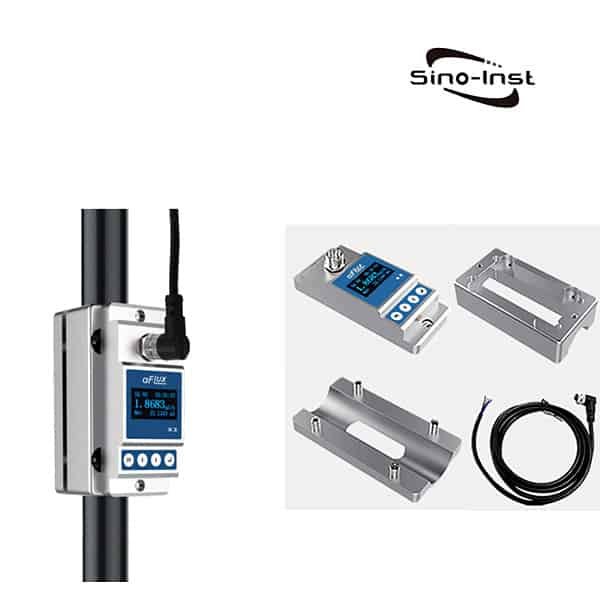
The capacitive level sensors are the key to the measurement process. The capacitive level sensors supplied by Sino-Inst all support signal output. Such as 4-20mA signal, pulse signal or communication protocol such as RS485.

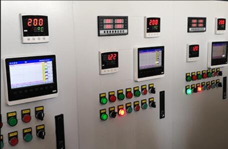
The liquid level recorder or volumetric recorder is the electronic unit that processes the signal from the sensors. It is connected to the sensors and is responsible for converting the capacitance measurement into a readable level measurement. The recorder can be configured to provide real-time data , historical data, and alarms. Making it an ideal solution for monitoring and controlling liquid levels in various industrial applications.
In conclusion, capacitive level measurement systems are a powerful and innovative solution for measuring the level of liquids in containers. Whether you’re looking to monitor liquid levels in real-time or need a historical record of your measurements, capacitive level measurement systems you covered.
Read more about: Liquid Volume Sensor? Monitors Liquid Volume Solutions
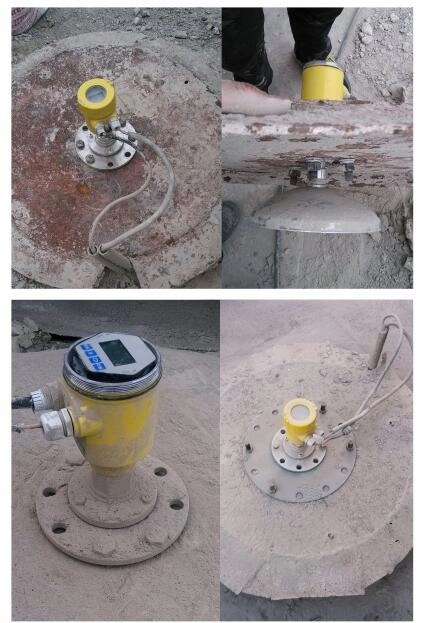
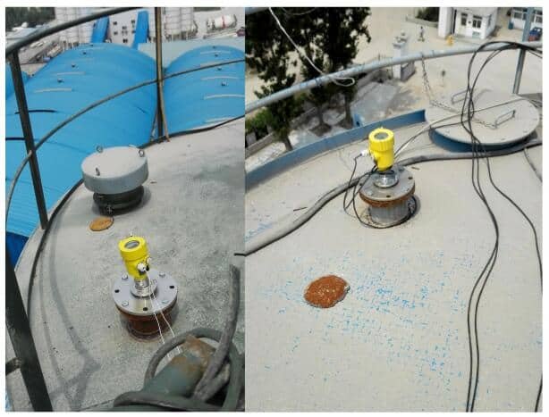
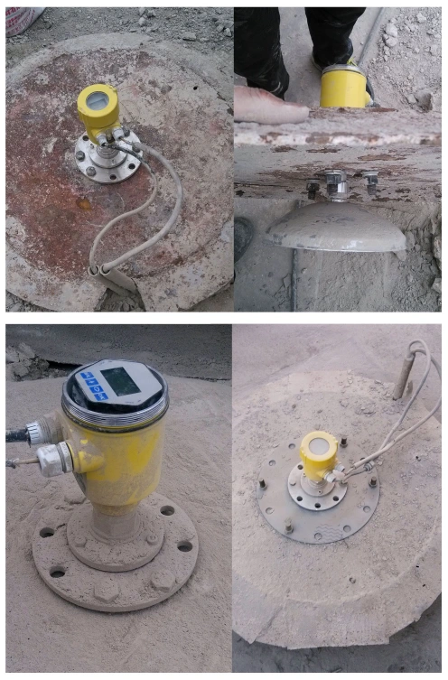
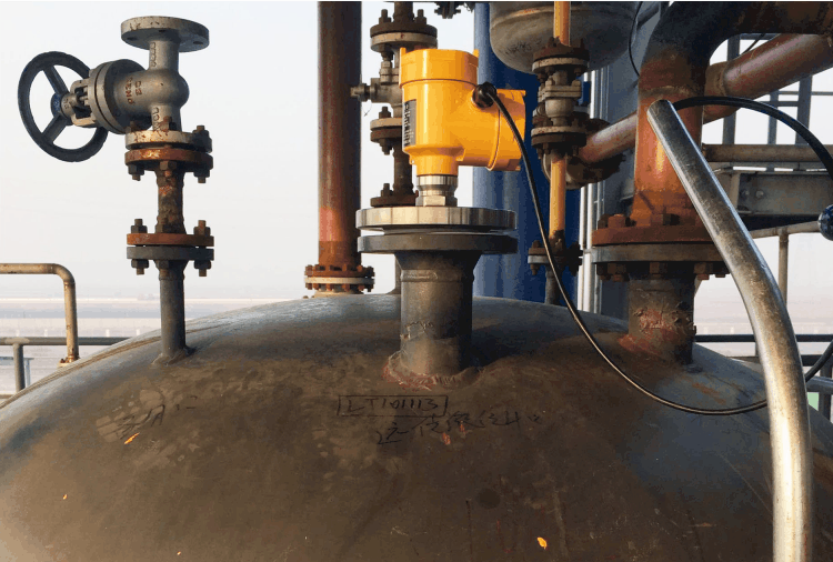
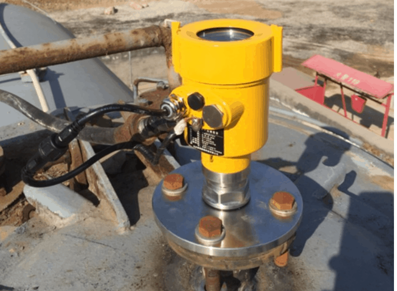
Applications of capacitive level sensors
Capacitive level sensors are used in a wide range of industries to accurately measure and monitor the level of various materials, making them an essential tool for maintaining efficiency, safety, and productivity.
Here’s a list of various industries that utilize capacitive level sensors:
| Industry | Example of Use |
| Agriculture | Measuring the level of irrigation water and chemicals in storage tanks used for crop production. |
| Automotive | Measuring the level of liquids in fuel tanks and coolant in engines, and monitoring the level of battery electrolyte in hybrid and electric vehicles. |
| Chemical | Measuring the level of liquids and powders in various production processes, such as mixers and reactors. Control Engineering |
| Food and Beverage | Measuring the level of liquids in tanks and containers, such as for dairy products and brewing. Food Engineering Magazine |
| Manufacturing | Monitoring the level of liquids and powders in various production processes, such as in pharmaceutical production. |
| Mining | Measuring the level of liquids and slurries in storage tanks and pipelines used in mineral processing, such as copper production. Mining Technology |
| Oil and Gas | Measuring the level of liquids and solids in various stages of production, such as in oil refineries and natural gas processing plants. |
| Pharmaceuticals | Measuring the level of liquids and powders in various production processes, such as mixers and reactors. Lab Manager Magazine |
| Low-temperature liquid measurement | Specially for liquid nitrogen, LNG, liquid ammonia and other low temperature environment liquid level measurement. Customized products. |
| Power Generation | Measuring the level of liquids and solids in power plant boilers, condensers, and cooling towers, such as in coal-fired power plants. |
| Water and Wastewater | Measuring the level of liquids in tanks and reservoirs, and monitoring the level of wastewater in treatment plants. WaterWorld |
These examples demonstrate the wide range of industries that use capacitive level sensors and the variety of applications for which they are used.

Advantages and limitations of capacitive level sensors
The advantages of using capacitive level sensors:
- Simple structure without any movable or elastic components. The result is high reliability and minimal maintenance. Under normal circumstances, there is no need to carry out routine major, medium and minor repairs.
- A variety of signal output, convenient for different system configurations.
- It is suitable for liquid level measurement of high temperature and high pressure containers. And the measured value is not affected by the temperature, specific gravity of the measured liquid, the shape and pressure of the container.
- It is especially suitable for the measurement of strong corrosive liquids such as acids and alkalis.
- There are perfect over-current, over-voltage, power polarity protection.
The limitations of capacitive level sensors
- Full working condition measurement cannot be implemented. There is “false water level” measurement, and it takes a long time to establish a stable differential pressure condition under unstable operating conditions such as boiler start, stop, emptying, continuous row, accident, etc.
- Under stable working conditions, due to structural limitations. It cannot solve the compensation problem of system measurement error caused by water side insulation.
- Under accident conditions such as boiler shortage and full water. Systematic measurement errors that are too large can have serious consequences.
- The construction scale is large and there are winter insulation problems.
- The measurement time lag is long. It cannot respond to boiler water level changes immediately. Poor quality of measurement signal conditioning.
- Due to the heat release of the condensing cylinder, the cost of use is relatively high.
Read more about: Which Sensor Is Best For Water Level?
Factors to consider when selecting a capacitive level sensor
After so many details. You may want to know, how should I choose a suitable capacitive level sensor? By our years of production experience. It is recommended that you consider the following points.

- Material compatibility: Material compatibility is very important because different materials can affect the accuracy of sensor readings or even damage the sensor. For example, materials such as PTFE or stainless steel can be used.
- Temperature range: Choosing a sensor that can work within the expected temperature range will ensure accurate readings. For example, common temperature ranges include 80℃, 100℃, high temperature 250℃, low temperature -196℃, etc.
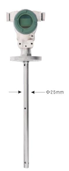
- Measuring range: For small measuring ranges, a rod-type probe can be selected. For larger measuring ranges, such as 8 meters or 10 meters, a cable-type probe can be selected.
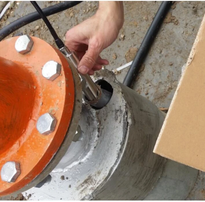
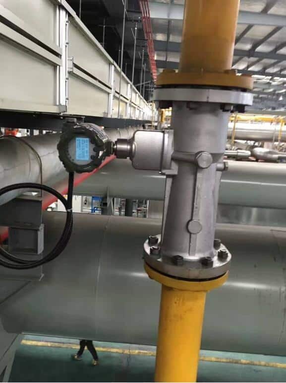
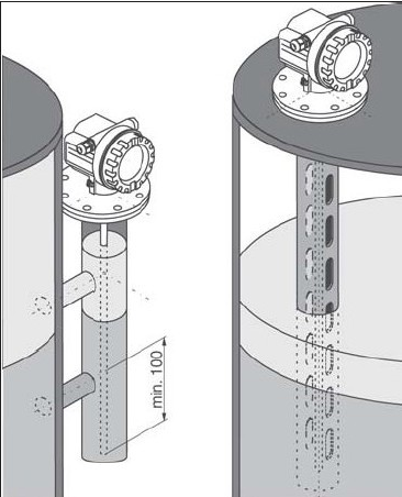
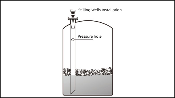
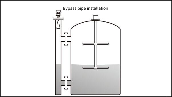
- Installation options: Installation size and location.
- Sensitivity: We generally provide a measurement accuracy of 0.5 or 1 level.
- Output type: For example, 4-20mA, 0-5V signal output. Or RS485, RS232 communication, etc.
- Pressure range: Common tank pressures include -0.1 MPa to 5 MPa. Some high-pressure sensors can be customized to withstand pressures up to 32 MPa.
- Special requirements: Such as explosion-proof, hygienic, and other requirements.
By considering these factors, you can ensure that you select a capacitive level sensor that meets the specific requirements of your application.
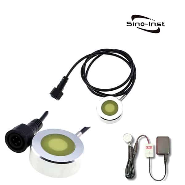
Of course, except for the capacitance level sensor. Ultrasonic level meter is also a commonly used one. Read More About: Factors To Consider When Choosing Explosion Proof Ultrasonic Level Sensors.
More Tank Level Measurement Solutions
Conclusion
In conclusion, capacitive level sensors are essential components in various industries. As they provide accurate, reliable, and non-contact level sensing. From agriculture to power generation, these sensors have proven to be efficient and effective in providing real-time measurements and controlling industrial processes.
When selecting a capacitive level sensor, it’s crucial to consider factors such as material compatibility, temperature range, measuring range, installation options, sensitivity, output type, pressure range, and any special requirements. Choosing the right sensor for your application will ensure accurate and reliable measurements and improve overall efficiency.
Therefore, if you are considering a capacitive level sensor for your application. You can contact our engnieer, who can help you select the right sensor that meets your specific needs.
Request a Quote


Wu Peng, born in 1980, is a highly respected and accomplished male engineer with extensive experience in the field of automation. With over 20 years of industry experience, Wu has made significant contributions to both academia and engineering projects.
Throughout his career, Wu Peng has participated in numerous national and international engineering projects. Some of his most notable projects include the development of an intelligent control system for oil refineries, the design of a cutting-edge distributed control system for petrochemical plants, and the optimization of control algorithms for natural gas pipelines.