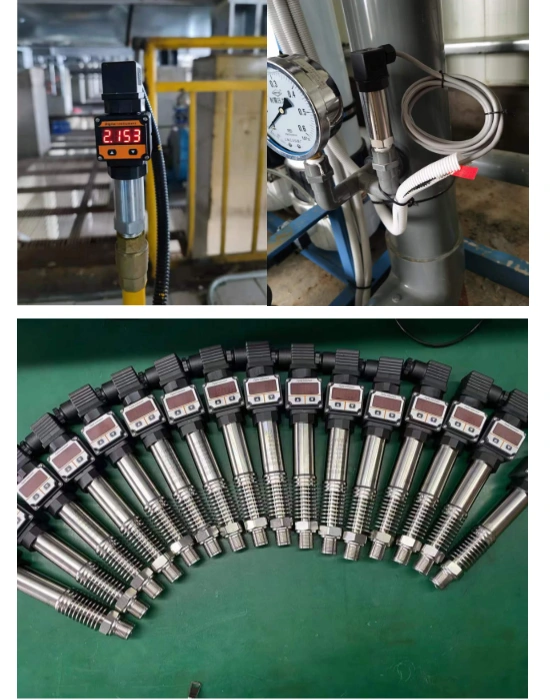
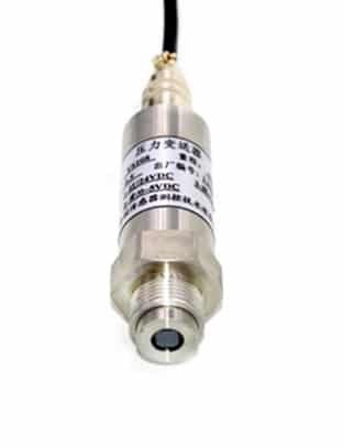
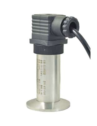
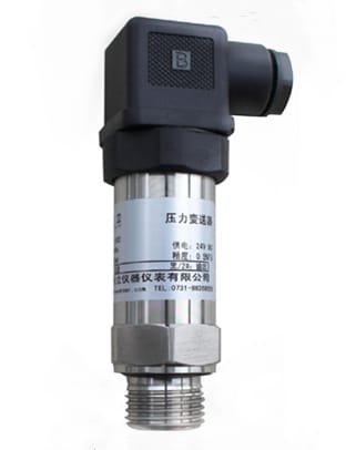
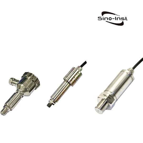
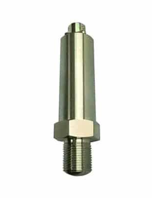
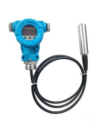
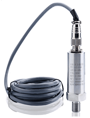
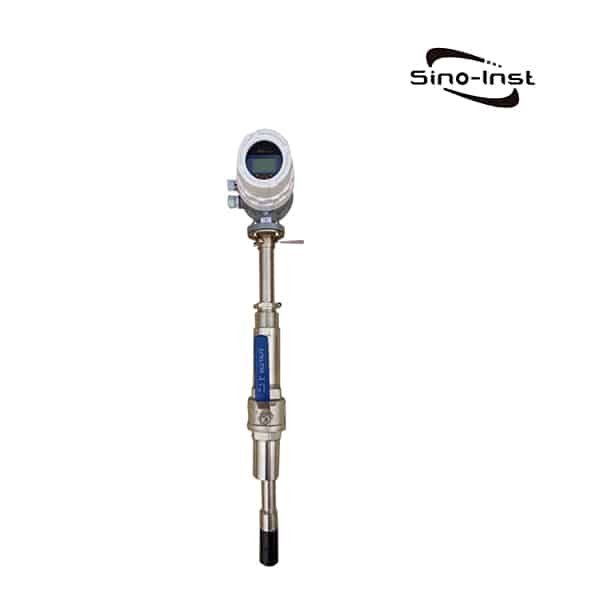
The Small Pressure Transducer/Sensor is characterized by its small size, the shortest can be 5CM. In some occasions where the installation location is small, it has an irreplaceable volume advantage. Small Pressure Transducer is that the pressure of the measured medium acts directly on the diaphragm of the sensor (stainless steel or ceramics). Make the diaphragm produce a micro-displacement proportional to the medium pressure. The resistance value of the sensor is changed, and the change is detected by the electronic circuit. And convert and output a standard measurement signal corresponding to this pressure. The interface, casing and electrical interface of the transmitter can be adapted according to the requirements of the user’s industry.
The Small Pressure Transducer/Sensor is characterized by its small size, the shortest can be 5CM. The interface, casing and electrical interface of the transmitter can be adapted according to the requirements of the user’s industry. The size of Small Pressure Transducer/Sensor also supports customization.
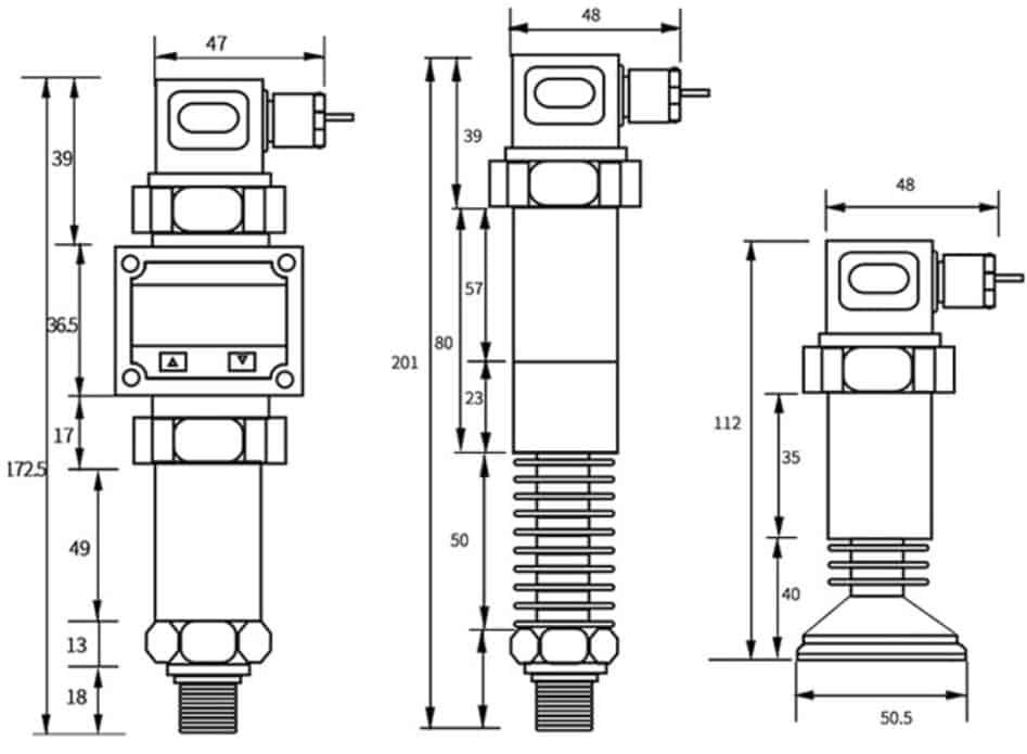
For example, the following product dimensions:
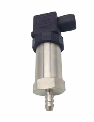
Miniature Pressure Sensor/Transducer
SI-51 Miniature Pressure Sensor/Transducer
Miniature Pressure Sensor is also called Miniature Pressure Transducer. The miniature pressure sensor is a miniature solid-state silicon force sensor integrated with MEMS technology. One-piece miniature stainless steel package. Make it have excellent dynamic performance. Small size, streamlined, strong, compact shape structure.
Product size Φ3, Φ5, M6, M8, M10. Can be specially designed according to specific working conditions;
Small size, streamlined appearance;
split structure. Optional standard voltage, current, digital signal output. Meet the requirements of various working conditions;
High dynamic frequency response, steep rising edge;
Wide measuring range. Any range between -100Kpa~0-10KPa…60MPa;
Low-pressure pressure transmitter is the application of conventional pressure sensor technology extended to the field of ultra-low pressure. While maintaining the original high performance, the pressure range can be as low as 0-5KPa. The advanced design makes this ultra-low pressure transmitter have the characteristics of fast response and good long-term stability.
The basic structure of its measurement part can be regarded as a space divided into two parts by the sensor. Including the case where one space is the entire universe.
When the pressures of these two parts are not equal, the force acting on the sensor causes the sensor to generate displacement or displacement tendency (force), and the pressure can be measured by detecting the displacement or displacement tendency.
Common sensors include diaphragms, spring tubes, and bellows, among which diaphragms are most widely used in transmitters.
There are many types of pressure sensors. Such as resistance strain gauge pressure sensors, semiconductor strain gauge pressure sensors, piezoresistive pressure sensors, inductive pressure sensors, capacitive pressure sensors, resonant pressure sensors, etc.
What’s the Difference Between a Pressure Transducer and a Pressure Switch? Simply put, the Pressure Transducer is a signal conversion and transmission device, and the pressure switch is a control switch device. This is the difference between a Pressure Transducer and a Pressure Switch. Let’s look at their differences in detail. And learn how to choose a pressure transmitter and pressure switch.
What does SCADA stand for? SCADA is the abbreviation of Supervisory Control And Data Acquisition. Namely data acquisition and monitoring control system. SCADA system is also called monitoring configuration software,…
Intrinsically safe type is an explosion-proof type of electrical equipment. When purchasing electrical equipment, do you often hear about intrinsic safety? For example, when ordering pressure transmitters or flow meters…
4-20mA to 0-10v voltage, this is I/V conversion. That is current-voltage conversion, usually used for long-distance signal transmission in the industry. How to convert a 4-20mA to 0-10V /1-5V signal?…
The Hydrostatic Pressure Transmitter measures the hydrostatic pressure exerted by a hydrostatic head. Use these hydrostatic pressure transmitters to measure the liquid level in storage tanks, processing vessels, collection tanks,…
What is a ceramic pressure sensor? Ceramic pressure sensors are sensor diaphragms made of ceramic alumina (Al2O3). Ceramic is a material with high elasticity, corrosion resistance, wear resistance, impact, and…
What Is Static Water Pressure? Definition of Static Water Pressure: Static Water Pressure refers to the pressure on water when it is stationary or moving in a straight line at…
High Temperature Pressure Transducer is also called High Temperature Pressure Sensor, or High Temperature Pressure Transmitter. The High Temperature Pressure Transducer is used for applications where the medium temperature exceeds…
What is underwater pressure transducer? Underwater pressure transducer refers to a type of pressure sensor that can be used underwater for a long time. The degree of protection of the…
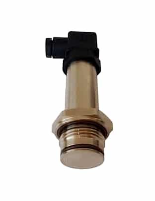
Small Pressure Transducer/Sensor-Low Cost-High Performance
Sino-Inst is a manufacturer of Small Pressure Transducer/Sensor. Small Pressure Transducers/Sensors have a lower cost than other industrial pressure transmitters. At the same time, Small Pressure Transducer/Sensor can customize high-performance parameters. Such as ultra-high temperature, ultra-high pressure, or micro-scale. Or special anti-corrosion materials, etc.
Sino-Inst is a manufacturer that produces and sells various types of automatic measurement and control instruments. The main products are: hydraulic pressure sensor, liquid level/water level sensor, Miniature Pressure Sensor/Transducer, micro pressure/negative pressure/vacuum pressure sensor, temperature transmitter, load cell and other pressure, differential pressure, liquid level, temperature , weighing sensors and various special pressure sensors and intelligent control systems.
If you need to purchase a Small Pressure Transducer/Sensor, or have any technical questions about Small Pressure Transducer/Sensor, please feel free to contact our engineers.
Request a Quote
Please enable JavaScript in your browser to submit the form
Wu Peng, born in 1980, is a highly respected and accomplished male engineer with extensive experience in the field of automation. With over 20 years of industry experience, Wu has made significant contributions to both academia and engineering projects.
Throughout his career, Wu Peng has participated in numerous national and international engineering projects. Some of his most notable projects include the development of an intelligent control system for oil refineries, the design of a cutting-edge distributed control system for petrochemical plants, and the optimization of control algorithms for natural gas pipelines.
What’s the Difference Between a Pressure Transducer and a Pressure Switch? Simply put, the Pressure Transducer is a signal conversion and transmission device, and the pressure switch is a control switch device. This is the difference between a Pressure Transducer and a Pressure Switch. Let’s look at their differences in detail. And learn how to choose a pressure transmitter and pressure switch.
Difference Between a Pressure Transducer and a Pressure Switch
The Pressure Transducer uses the output as a standard signal, and is composed of a pressure-sensitive element and a conversion circuit. Using the pressure of the measured medium to produce a small change of current or voltage output on the pressure sensitive element.
The transmitter often needs to be used in conjunction with an external amplifier circuit to complete the process from pressure detection to control and display. Since the pressure sensor is a primary component, the signal fed back by the pressure sensor needs to be processed, analyzed, stored, and controlled by the measurement and control system. Make industrial automation equipment and engineering operation control more intelligent.
The pressure switch is a simple control device. When the measured pressure reaches the set value, it will automatically send out an alarm or control the function of turning on or off.
The pressure switch needs to be opened or closed under the set pressure. It can be used for simple control, and the output is the switch value.
The output of the pressure transmitter can be an analog signal or a digital signal. The post-processing is convenient, and it can also be converted into a standard transmitter signal for remote transmission.
If you want to know more about pressure sensors, you can consult Sino-Inst, thank you!
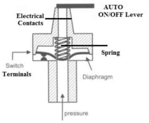
What is Pressure Switch?
A pressure switch is a mechanical switch that is activated by pressure to a set point. The switch is used to control a circuit by turning it on and off. Here the pressure point at which the switch is triggered is called the set point. The pressure threshold at which the switch is disabled is called the cut-off point. With enough force, the contacts can open or close the switch depending on their configuration.
This is a device that activates an electrical contact when a fixed fluid pressure is reached. Typically, this switch has two functions. The main function is to maintain the pressure or reservoir level of the system. The secondary function is to prevent equipment from operating at a lower efficiency or from being harmed. Its notation is as follows:
Structure of the pressure switch
The structure of the pressure switch mainly includes five parts. These are diaphragm, adjustment spring, lever, electrical contacts and terminals.
The diaphragm in this switch acts like a sensing element and is therefore used to detect pressure. This element is usually made of a pressure-sensitive, flexible material.
Adjusting the spring will change the set point or cut point, some switches have separate springs that control the set point and cut point.
The AUTO/OFF lever is used to manually activate or deactivate the switch, this lever is very helpful to turn off the switch throughout the installation or maintenance process. Sometimes, a knob is used instead of a lever, but the principle works the same.
The electrical contacts allow current to flow through them once they are contacted by an external power source. The terminals of the switch are used to connect an external power source to the contacts.
A pressure switch works by operating an electrical contact once a fixed fluid pressure is reached. The switch will make electrical contact when the pressure increases or the pressure decreases from a fixed preset pressure level.
Type of pressure switch
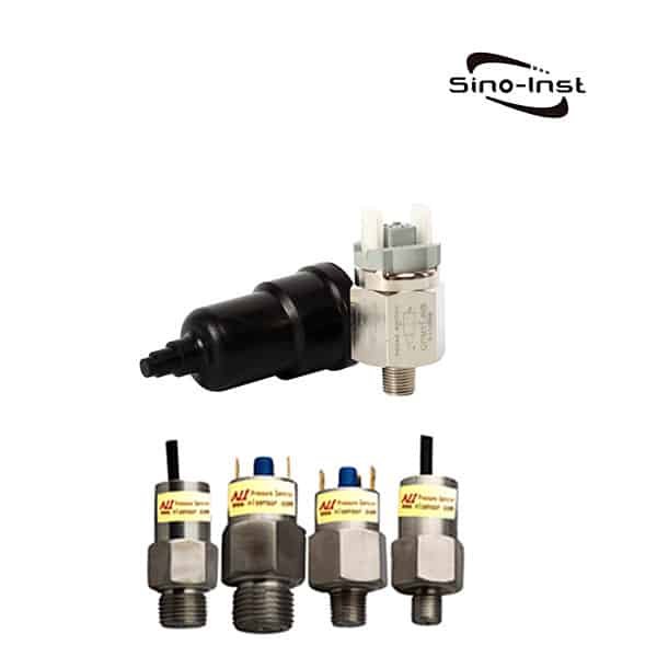
There are two types of pressure switches on the market today, mechanical and electronic.
Mechanical pressure switches are the most widely used due to their lower cost and ease of use compared to electronic pressure switches. These switches can be equipped with a mechanical pressure sensing element that deforms in response to fluid pressure. The different types of mechanical pressure switches are discussed below.
Piston pressure switch This type of switch is the most popular and is widely used in different applications. Once the pressure of the fluid changes, it moves the piston axially, which triggers the switch. The switch can directly or indirectly detect the pressure of the liquid. Therefore, direct inspection mainly involves seals like O-rings. to prevent liquids from entering the components. Whereas indirect detection mainly involves a flexible diaphragm that separates the piston from the fluid.
Diaphragm pressure switch This is a high quality switch primarily developed for safety critical applications. The main benefit of diaphragm pressure switches is that no voltage supply is required for the switching process. The switch consists of a metal membrane that is directly connected to the soaker portion of the switch and the diaphragm that activates the switch. The switch is used for monitoring process pressure and control in different industries such as chemical, petrochemical, natural gas, oil etc.
Bourdon tube pressure switch This is an elastomer or flexible metal tube that attaches to one end of the switch while leaving the other end free to move. Once the pressure of the liquid in the tube rises, it tends to level, and this movement is then used primarily to activate the switch. These switches are suitable for different applications such as chemical, general power stations and petrochemical as long as the operating force is medium to high.
Differential pressure switch This switch is useful when evaluating the force between two points within a system simply connected to two process ports on the upper or lower part of the device. If the pressure difference between the two sides increases by a certain threshold, the switch can be triggered. These switches are suitable for monitoring pressure drops in screens, filters and tank levels.
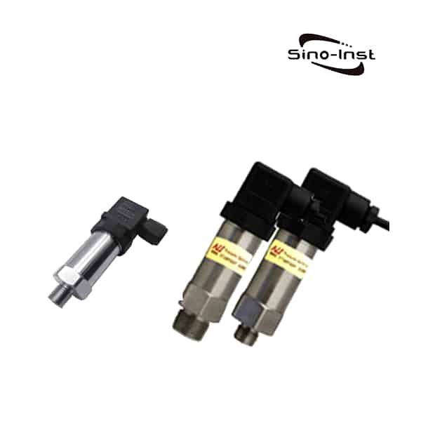
Electronic pressure switch. It can be used with pressure sensors such as strain gauges. These types of switches have analog capabilities, so they are not limited to an on or off position. Continuous and variable signals can also be transmitted for more precise monitoring. Therefore, these are not only switches, but also measuring instruments or transmitters. Some additional features of these electronic switches are field programmability of switching functions, time delays, hysteresis, set points, etc.
A pressure transducer is a device that converts pressure into a pneumatic signal or an electric signal for control and remote transmission.
It can convert the physical pressure parameters such as gas and liquid felt by the load cell sensor into a standard electrical signal (such as 4~20mADC, etc.). It can be used to supply secondary instruments such as indicating alarms, recorders, and regulators for measurement and indication, and process regulation.
Working Principle of Pressure Transducer
Pressure Transducer Electrical components that feel pressure are generally resistance strain gauges. The resistance strain gauge is a sensitive device that converts the pressure on the device under test into an electrical signal. The most widely used strain gauges are metal resistance strain gauges and semiconductor strain gauges.
There are two types of metal resistance strain gauges: wire strain gauges and metal foil strain gauges. Usually, the strain gauges are tightly bonded to the mechanical strain-generating substrate through a special adhesive. When the stress of the substrate changes, the resistance strain gauge also deforms together. Change the resistance value of the strain gauge, so that the voltage applied to the resistance changes.
The types of pressure transmitters are roughly as follows: resistance strain gauge pressure transmitters, semiconductor strain gauge pressure transmitters, piezoresistive pressure transmitters, inductive pressure transmitters, capacitive pressure transmitters, Resonant pressure transmitter and capacitive acceleration sensor, etc.
Piezoresistive pressure transmitter
The resistance strain gauge is a sensitive device that converts the strain change on the tested object into an electrical signal. It is one of the main components of piezoresistive strain transmitters. There are two kinds of resistance strain gauges, metal resistance strain gauges and semiconductor strain gauges.
Usually, the strain gauges are tightly bonded to the substrate that generates mechanical strain through a special adhesive. When the stress of the substrate changes, the resistance strain gauge also deforms together. Change the resistance of the strain gauge. This changes the voltage across the resistor.
Ceramic pressure transmitter
Principle Corrosion-resistant pressure transmitters have no liquid transfer, and the pressure acts directly on the front surface of the ceramic diaphragm. To make the diaphragm slightly deformed, thick film resistors are printed on the back of the ceramic diaphragm and connected to form a Wheatstone bridge.
Due to the piezoresistive effect of the varistor, the bridge produces a highly linear voltage signal proportional to the pressure and proportional to the excitation voltage. The standard signal is calibrated as 2.0 / 3.0 / 3.3 mV/V according to different pressure ranges. Compatible with strain gauge sensors.
Through laser calibration, the sensor has high temperature stability and time stability. The sensor comes with a temperature compensation of 0-70°C, and can be in direct contact with most media. ,
Diffused silicon pressure transmitter
The pressure of the measured medium acts directly on the diaphragm of the sensor, causing the diaphragm to produce a micro-displacement proportional to the pressure of the medium. The resistance value of the sensor is changed, and the change is detected by the electronic circuit. And convert and output a standard measurement signal corresponding to this pressure.
The piezoelectric materials mainly used in piezoelectric sensors include quartz, potassium sodium tartrate, and ammonium dihydrogen phosphate. Among them, quartz is a natural crystal in which the piezoelectric effect is found. Within a certain temperature range, the piezoelectric properties always exist, but when the temperature exceeds this range, the piezoelectric properties disappear.
Ceramic capacitive sensors are available for measurements in normal or aggressive media. Materials such as gas, gas or liquid, but not prone to precipitation, crystallization or stiffening are recommended. Applied to tank liquid level measurement, sea water, water on board, diesel oil, waste oil.
Selection of pressure switch and pressure transmitter
Both pressure switches and pressure transmitters are intelligent digital display pressure measurement products integrating pressure measurement, display, output and control. When choosing, you only need to remember the following 6 points to know what kind of pressure switch and pressure transmitter to use.
According to the characteristics of pressure switch and pressure transmitter, you can start from the following data that need to be measured:
The measured medium and the actual condition of the medium
The measured pressure range
Required measuring range
The temperature of the working conditions on site
The connection method used in conjunction with the working conditions
Installation location
According to the above 6 points of data and requirements, you can know what kind of pressure switch or pressure transmitter is needed. In addition, pressure switches and pressure transmitters are all non-standard customized products. It can be used according to the site Working conditions to decide.
What Is Flush Diaphragm Pressure Transducer? A flush diaphragm pressure transducer is a type of pressure sensor that measures the pressure of a fluid or gas by using a diaphragm…
Different Types of Pressure have different characteristics. Different pressure transmitters bear different pressure types. Common pressure types include absolute pressure, gauge pressure, negative pressure or vacuum, and differential pressure. Each…
As a clean energy, natural gas is widely used in many aspects such as industrial production, thermal power generation and residential gas heating. Although natural gas pipeline transportation has many…
The static pressure sensor or static pressure transmitter is based on atmospheric pressure or absolute vacuum, and compares the difference between the measured pressure and atmospheric pressure or absolute vacuum…
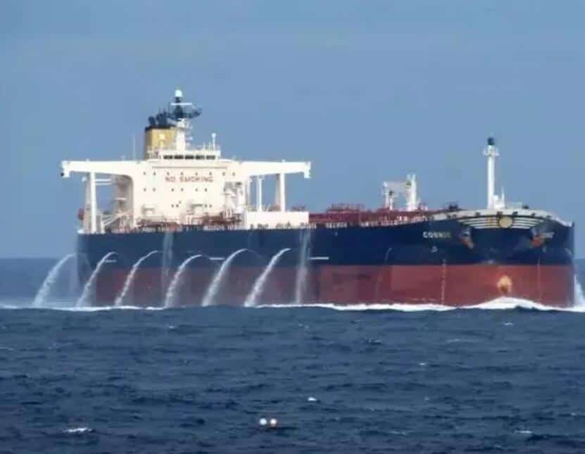
Ship Ballast Tank is to point to the ship’s ballast tank to load ballast to adjust the ship’s draft and metacentric height. It is an operation to ensure that the…
Do you know the difference between Pressure Transmitter vs Pressure Gauge? Pressure transmitters and pressure gauges are industrial process instruments used to measure the pressure of media.Understanding the difference between…
Pressure Transmitter 4-20mA is the most commonly used one in industrial process control. In industrial process control, the measurement and control of pressure has always been a very important parameter…
What is a gas pressure sensor? Gas Pressure Sensors are also called Gas Pressure Transducers. Gas Pressure Sensors convert gas pressure into standard electrical signals, such as 4~20mADC. Measurement, indication…
Sino-Inst is a manufacturer of Pressure Transducer and a Pressure Switch. We produce and sell all kinds of automatic measurement and control instruments and meters. The main products are: hydraulic pressure sensor, liquid level/water level sensor, Miniature Pressure Sensor/Transducer, micro pressure/negative pressure/vacuum pressure sensor, temperature transmitter, load cell and other pressure, differential pressure, liquid level, temperature , weighing sensors and various special pressure sensors and intelligent control systems.
Pressure Transducer and a Pressure Switch are commonly used instruments in industrial production process. The pressure switch turns the switch on or off at your given pressure. The output of the pressure sensor can be an analog signal or a digital signal, which is convenient for subsequent processing, and can also be converted into a standard transmitter signal for remote transmission.
If you need to purchase a Pressure Transducer and a Pressure Switch, or have any technical questions about Pressure Sensor/Transducer, please feel free to contact our engineers.
Request a Quote
Please enable JavaScript in your browser to submit the form
Wu Peng, born in 1980, is a highly respected and accomplished male engineer with extensive experience in the field of automation. With over 20 years of industry experience, Wu has made significant contributions to both academia and engineering projects.
Throughout his career, Wu Peng has participated in numerous national and international engineering projects. Some of his most notable projects include the development of an intelligent control system for oil refineries, the design of a cutting-edge distributed control system for petrochemical plants, and the optimization of control algorithms for natural gas pipelines.
A flow meter is an instrument used to measure and indicate the volume or mass of a gas or liquid. Simply put, it is an instrument used to measure the flow of fluid in pipes or open channels. Also known as flow indicator, liquid flow meter, flow sensor, etc.
Flowmeters are further divided into differential pressure flowmeters, rotameters, throttling flowmeters, slit flowmeters, volumetric flowmeters, electromagnetic flowmeters, ultrasonic flowmeters, etc. According to the medium, it can be divided into: liquid flowmeter and gas flowmeter.
Flow meter calibration is carried out according to the verification regulations of various flow meters promulgated by the National Metrology Bureau.
For the flowmeters used, except for the standard throttling device, no experimental verification is required. The rest of the flowmeters are almost all verified when they leave the factory. During the use of the flowmeter, it should also be calibrated frequently.
The calibration methods of liquid flowmeter mainly include volumetric method, mass method, standard volume tube method and standard flowmeter comparison method.
The calibration methods of gas flowmeter mainly include sonic nozzle method, servo standard flowmeter comparison method and bell jar method.
Why is it important to calibrate a flow meter?
Most people recognize that a flow meter should be calibrated before it is put into service, but why is flow meter calibration so important?
The flow meter calibration process involves comparing the flow meter to a reference device used as a calibration standard. Calibration of reference equipment should be traceable to national or international standards. The next step involves adjusting the flow meter (if necessary) to counteract any errors.
If, like thousands of other facilities, flow meters are used in your process, it makes good business sense to ensure that the flow meters you use are giving you accurate and consistent information.
No matter what fluid you are metering, the liquid, gas or steam used in the process is most likely a valuable commodity. Accurate flow meter performance is therefore an invaluable part of business planning and costing.
At the same time, Calibration Flow Meters are also very important for the control of material consumption in our industrial production process. Can effectively improve production efficiency. reduce manufacturing cost.
Flow Meter Calibration vs. Recalibration
Flow Meter Verification (Verification): Refers to the process of identifying and confirming whether measuring instruments meet the statutory requirements. It includes inspection, marking and/or issuing a certificate.
Flow Meter Calibration (Calibration): refers to the determination of the value indicated by a measuring instrument or measuring system, or the value represented by a physical measuring tool or reference material, and the corresponding value reproduced by a standard under specified conditions. A set of operations on relationships.
After reading the definition, there must be some confusion, right? We usually summarize the main differences between verification and calibration into nine aspects:
Different purposes;
Objects are different;
According to different;
Different in nature;
The cycle is different;
In different ways;
The content of the certificate is different;
Different conclusions;
The authorities are different.
For quick understanding, we simply organize the following table:
Verification and Calibration
Verification
Calibration
Definition of Terms
Refers to the process of identifying and confirming whether measuring instruments meet the statutory requirements, which includes inspection, marking (or) issuing a verification certificate.
Refers to a set of operations to determine the relationship between the value indicated by a measuring instrument or measuring system, or the value represented by a physical measuring tool or reference material, and the corresponding value reproduced by the standard under specified conditions .
Character
It belongs to mandatory verification and has legality;
Users can voluntarily trace the source, which is not legal;
Certificate form
If the test result is qualified, a “Certificate of Test” shall be issued; If it is unqualified, a “Notification of Verification Result” shall be issued
Usually a “Calibration Certificate” or “Calibration Report” is issued; calibration results can also be expressed in the form of calibration curves or calibration factors
Specific method
According to the verification regulations, each point is verified 3 times at 100%, 50%, 20% and 100% of the full scale. If the original coefficient is qualified, the coefficient is not adjusted in principle.
According to the calibration procedure, at 100%, 50%, 20% and 100% of the full scale each point 3 times, adjust the coefficient to obtain the best performance near the user’s actual flow. The nameplate remains the same, but the certificate reflects the change.
How to Calibrate a Flow Meter?
The volumetric method is the most commonly used. This is a method of measuring the volume of fluid flowing into a constant volume container within the measurement time to obtain the flow rate.
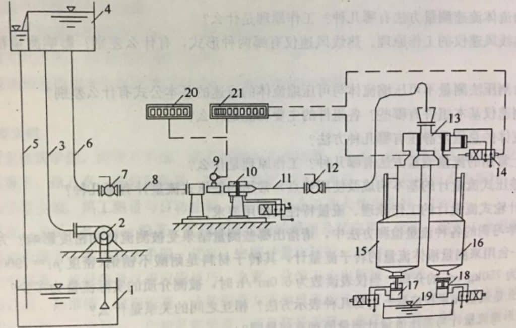
The figure below is a schematic diagram of the typical structure of the static volume method water flow verification device. Verify the flow meter with pulse output, and replace 21 for verification of other output flow meters.
The commutator 13 is used to change the flow direction of the fluid so that water flows into the standard container (the standard container 15 or 16 can be selected according to the flow rate). The pulse counting controller 21 is triggered when the commutator 13 starts. To ensure the simultaneous measurement of water and pulse signal counts.
When calibrating, use the pump to draw the test fluid from the liquid storage container into the high level water tank. Then through the school flow meter. If standard container 15 is selected, then close drain valve 17, open drain valve 18, and commutator 13 is placed in the position that makes water flow to standard container 16.
After the flow is stabilized, the commutator 13 is started. Water flow is changed into standard container 15 by standard container 16. At the same time, the trigger pulse counter accumulates the pulse number of the calibrated flowmeter. When the predetermined water volume or preset pulse number is reached, the commutator will automatically change direction. Water flow is changed into standard container 16 by standard container 15. Read off the volume V of the fluid that enters the standard container during this period of time from the scale on the reading glass tube of the container. Record the number of pulses N displayed by the pulse count control 21 for the flow meter being calibrated.
Compare the pulse number N of the calibrated flowmeter with the obtained standard volume V to determine the instrument constant and accuracy of the calibrated flowmeter. The instantaneous flow rate of the flowmeter is indicated by the frequency indicator 20 .
The system accuracy of this method can reach 0.2%.
When calibrating, use a pump to draw the test fluid from the liquid storage container through the flowmeter to be calibrated and then enter the container containing the liquid. Measure the temperature of the fluid while weighing it out. It is used to determine the density value of the measured fluid at this temperature.
The volume of the fluid can be obtained by dividing the weight of the measured fluid by the density of the fluid at the measured temperature. Compare it with the volume indication (accumulated pulse number) of the meter. The meter constant and accuracy of the flowmeter to be calibrated can be determined.
The accuracy of this method system can reach 0.1%
The working principle of the standard volumetric tube method is based on the volumetric method (standard volumetric method), but it is a dynamic measurement.
The standard flowmeter comparison method is to connect the flowmeter to be calibrated and the standard flowmeter in series on the pipeline flowing through the test fluid. The error is calculated by comparing the two measured values. The accuracy of the standard flowmeter is 2 to 3 times higher than that of the schooled flowmeter.
The sonic nozzle gas flow standard device is a standard instrument based on the sonic nozzle. It is used to verify mass flowmeters, velocity flowmeters, volume flowmeters, rotameters, differential pressure flowmeters or other types of flowmeters. It is a standard device for measurement and testing units and large enterprises to measure and calibrate gas flowmeters.
According to the principle of aerodynamics, when the pressure ratio between the upstream and downstream of the factor nozzle reaches a critical state, the throat airflow reaches the peak velocity, and the mass flow through the nozzle also reaches the peak value. This value is only related to the parameter at the nozzle inlet and is not affected by changes in downstream conditions. Based on the above principles, this system uses the sonic nozzle as a standard meter to calibrate the measured flowmeter.
Many users search How to Calibrate a Flow Meter? In order to understand how to adjust the accuracy of the flowmeter in your own working conditions.
On-site “flow comparison” means that the flowmeter is compared with other “reference flows” on site.
For example, the measured value of the temporarily clamped ultrasonic flowmeter, the volume of the liquid that has been measured over the flow in the piping system, etc. can be used as the “reference flow”.
For the meaning of terms such as on-site calibration, comparison and verification, please refer to the standard definitions in relevant documents, and will not repeat them here.
In practice, many professionals have explored various on-site comparison methods and indirect inspection methods. There are mainly 3 types:
(1) Use the container weighing method comparison of storage containers, working containers, pools or weighing instruments in the process. The pool volume comparison method is often used by water supply companies. Water plants can obtain high comparison accuracy by taking advantage of the favorable conditions of large-volume clear water pools.
(2) Reserve a position in the pipeline of the flowmeter to be tested for the flowmeter comparison method of connecting the reference flowmeter.
(3) Ultrasonic flowmeter comparison method of Clamp-on ultrasonic transducer. Clamp-on ultrasonic flowmeter is one of the three most promising methods of flow measurement. Especially the measurement accuracy error of existing foreign products is < ± 0.5%. This is conducive to the establishment of high-precision comparative detection and on-site online calibration system. It is convenient for the metrology and verification department to go to the site for calibration and testing.
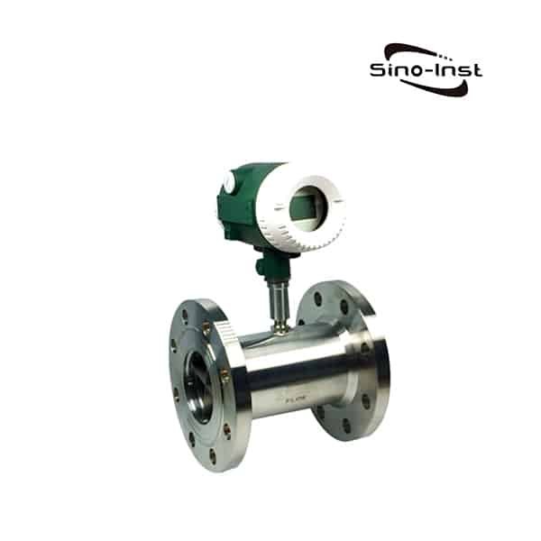
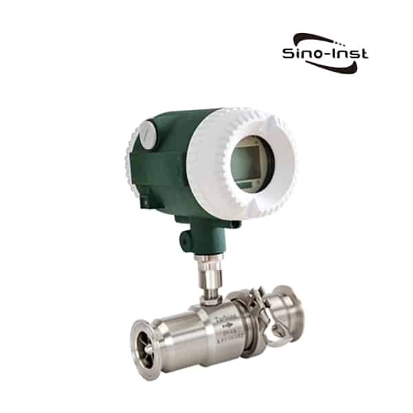
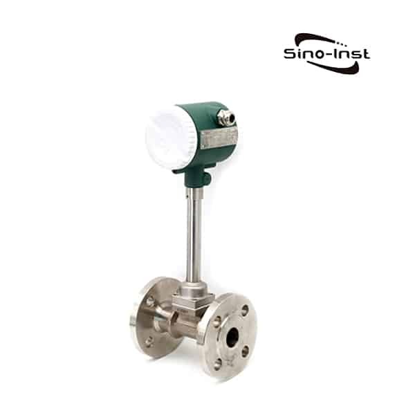
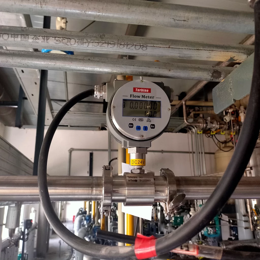
Turbine Flow Meter Installation Guidelines and Troubleshooting is compiled based on our Sino-Inst’s many years of experience in producing and supplying turbine flow meters.Whether it is a liquid turbine flow…
Sea Water Flow Measurement is becoming more and more important to many industries. Seawater can be directly used as production water in printing and dyeing, pharmaceutical, alkali making, rubber and…
Mechanical diesel flow meter is a volumetric meter for continuous or intermittent measurement and control of diesel or other liquid flow in pipelines. It has many advantages such as large…
Are high pressure flow meters the same as regular flow meters? Can high pressure flow meters be replaced by ordinary flow meters?Of course not. You need to measure the flow…
High pressure rotameter is suitable for flow measurement of high pressure liquid and gas.Standard type rotameter: DN15-DN50, can withstand 4.0MPa. High pressure rotameter: DN15-DN50, can withstand 25MPa. The pressure level…
What is Metal Tube Flow Meter? LZ series metal tube flow meter, also known as metal rotor flowmeter. Metal tube flow meter consists of a measuring tube and side indicator,…
Flow Pressure Transducers are measurements of fluid pressure within a pipeline. When fluid flows through a pipe, pressure acts on the pipe wall. The medium in the pipeline can be…
What is an insertion flow meter? Insertion flowmeter is a type of flowmeter in which the measuring probe is inserted into the pipe to measure the flow. This is a…
The above is “How to Calibrate a Flow Meter?” I hope it will be helpful to everyone.
Flowmeter calibration method is the trend of measurement technology development. In particular, the use of portable ultrasonic flowmeters to carry out online flowmeter calibration is a feasible method. It can greatly facilitate the on-site measurement and calibration work. It can effectively reduce the capital consumption in metering and is easy to popularize and apply.
The data shows that through the research and application of on-site calibration technology for flow metering instruments. Can improve the measurement detection level. , to achieve the purpose of periodic measurement verification. To make the online flowmeter measurement data accurate and reliable, as long as it is operated accurately. Minimize random and additive errors. It can meet the requirements of the relevant state departments for the accuracy of industrial and civil water measurement.
Sino-Inst is a manufacturer of Calibration Flow Meters. We offer more than 50 Calibration Flow Meters.
Sino-Inst provides customers with professional and targeted system solutions to help customers solve various problems encountered in production, optimize control and improve product quality.
If you need to purchase flowmeters, or consult technical questions about flowmeters, please feel free to contact us.
Request a Quote
Please enable JavaScript in your browser to submit the form
Wu Peng, born in 1980, is a highly respected and accomplished male engineer with extensive experience in the field of automation. With over 20 years of industry experience, Wu has made significant contributions to both academia and engineering projects.
Throughout his career, Wu Peng has participated in numerous national and international engineering projects. Some of his most notable projects include the development of an intelligent control system for oil refineries, the design of a cutting-edge distributed control system for petrochemical plants, and the optimization of control algorithms for natural gas pipelines.
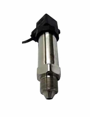
A flush diaphragm pressure transducer is a type of pressure sensor that measures the pressure of a fluid or gas by using a diaphragm. The diaphragm is flush with the surface of the vessel or pipe in which the pressure is being measured. These types of pressure transducers are commonly used in a variety of applications. Including process control, hydraulic and pneumatic systems, and fluid level measurement.
A flush diaphragm pressure transducer is a type of pressure sensor that measures the pressure of a fluid or gas by using a diaphragm that is flush with the surface of the sensor. This type of transducer is commonly used in applications where the pressure being measured is in contact with the transducer. Such as in hydraulic systems or in process control applications.
There are several types of flush diaphragm pressure transducers, including:
Capacitive flush diaphragm pressure transducers: These transducers use a capacitive sensing element to measure pressure. The diaphragm is typically made of a dielectric material. Such as ceramic or polycarbonate, which allows the transducer to measure the change in capacitance as the diaphragm moves in response to pressure.
Piezoresistive flush diaphragm pressure transducers: These transducers use a piezoresistive sensing element to measure pressure. The diaphragm is typically made of a piezoresistive material, such as silicon. Which allows the transducer to measure the change in resistance as the diaphragm moves in response to pressure.
Strain gauge flush diaphragm pressure transducers: These transducers use a strain gauge sensing element to measure pressure. The diaphragm is typically made of a material that deforms under pressure, such as metal or plastic. And the strain gauge measures the change in resistance as the diaphragm deforms.
Flush diaphragm pressure transducers are known for their high accuracy, fast response time, and low hysteresis. They are also typically easy to install, as they do not require any additional mounting hardware or seals. However, they are not as durable as other types of pressure transducers and may be susceptible to damage if they are subjected to high pressure or impact.
Flush diaphragm pressure transducers have a number of advantages that make them well-suited for use in a wide range of applications. Some of the key benefits of flush diaphragm pressure transducers are outlined below.
Sanitary design:
Widely used in food, sanitation and brewing industries. Feel the pressure directly with the hygienic flat membrane. The hygienic flat diaphragm prevents fouling, unhygienic and clogging by viscous liquids.
Accurate measurement:
Flush diaphragm pressure transducers are accuracy and reliability when it comes to pressure measurement. The flush diaphragm design allows the transducer to make a direct contact with the fluid or gas being measured. Which helps to eliminate the potential for to temperature or viscosity changes. This makes flush diaphragm transducers an ideal choice for applications where accurate measurement is critical.
Versatility:
Flush diaphragm pressure transducers can be used to measure a wide range of pressures, from low to high. Making them suitable for use in a variety of applications. They can be used to measure gauge, absolute, or differential pressure, and are available in a range of materials to suit different media. More about: Absolute Pressure Vs Gauge Pressure.
Easy installation:
Flush diaphragm pressure transducers are relatively easy to install and require minimal maintenance. They can be mounted in any orientation and do not require any additional components or sensors to function.
Robust design:
Flush diaphragm pressure transducers are designed to be rugged and durable. Making them suitable for use in harsh or demanding environments. They can withstand high temperatures, pressure spikes, and other extreme conditions without breaking or failing.
Long-lasting:
With proper care and maintenance, flush diaphragm pressure transducers can have a long service life. Making them a cost-effective choice for applications where they will be in use for an extended period of time.
In summary, flush diaphragm pressure transducers are an accurate, versatile, and reliable choice for pressure measurement in a variety of applications. They are easy to install, robust, and long-lasting, making them a popular choice among engineers and technicians.
A flush diaphragm pressure transducer is a type of pressure sensor that is used to measure the pressure of a fluid or gas. It is called a “flush” diaphragm pressure transducer because it has a diaphragm that is flush with the surface of the sensor. This type of transducer is preferred in certain situations because it has several unique features and benefits.
A flush diaphragm pressure sensor is a pressure sensor designed with a smooth, flat surface that is flush with the process being measured. This makes them ideal for use in hygiene-sensitive industries. Such as food and beverage processing, pharmaceuticals and medical device manufacturing. Where it is important to minimize the risk of contaminants becoming trapped in crevices or protruding parts.
Flush diaphragm pressure sensors are used to measure the pressure of liquids, gases, and vapors in a variety of applications. Including process control, safety systems, and quality control. They are especially suitable for monitoring pressure changes in critical process streams. Such as fermentation in beer production or sterilization in medical device production.
One reason to choose a flush diaphragm pressure transducer is when the media being measured is highly viscous or contains particles that could damage the diaphragm of a traditional pressure transducer. The flush diaphragm design protects the diaphragm from being damaged by these mak contaminated it durable and reliable choice.
Another reason to choose a flush diaphragm pressure transducer is when the media being measured is at high temperatures. Traditional pressure transducers can be sensitive to temperature and may not provide accurate readings at high temperatures. The flush diaphragm design, on the others for hand, a more stable and accurate measurement at high temperatures.
In addition to these specific circumstances, flush diaphragm pressure transducers are often preferred in situations where a high level of accuracy and reliability is required. They are typically more expensive than traditional pressure transducers, but their durability and accuracy make them less susceptible to injury .
Overall, flush diaphragm pressure transducers are a useful tool for measuring the pressure of fluids and gases in a variety of applications. They are particularly well-suited for use in high temperature, high pressure, or high viscosity environments. And are preferred in situations where accuracy and reliability are of the utmost importance.
A flush diaphragm is a type of mechanical device that is used to seal off or control the flow of a fluid through a pipe or passageway. It consists of a flexible membrane or diaphragm that is attached to a rigid frame and is positioned within a pipe or valve body.
The diaphragm is designed to move in response to changes in the pressure or flow of the fluid, allowing the device to open or close in order to regulate the flow of the fluid.
Flush diaphragms are commonly used in a variety of applications, including in process control systems, fluid handling equipment, and industrial piping systems. They are known for their durability, reliability, and ability to maintain a tight seal over a wide range of operating conditions.
This type of pressure sensor is also commonly known as: Flat film pressure sensor. Diaphragm pressure transmitter. Paint pressure sensor. Food pressure sensor. Diaphragm pressure sensor. Diaphragm pressure transmitter. Or sanitary pressure transmitter.
Flush diaphragm pressure sensor, including strain type and diffused silicon front type.
The strain-type flush-membrane measuring end adopts a special, sturdy flush diaphragm. Hard particles in the measured medium will not damage the isolating diaphragm. Compact structure, corrosion resistance, anti-vibration, anti-particle impact, wide temperature compensation.
Diffusion silicon front type is made of imported diffusion silicon core. Use calibration and digital compensation technology. The product has reliable performance and stable output.
A diaphragm pressure transducer works by converting pressure into an electrical signal.
It consists of a diaphragm that is exposed to the pressure being measured, a strain gauge that is attached to the diaphragm. And an electrical circuit that is connected to the strain gauge.
When the diaphragm is subjected to pressure, it flexes and causes the strain gauge to also deform. This deformation causes a change in the electrical resistance of the strain gauge. Which the electrical circuit detects and converts into an electrical signal.
The magnitude of the electrical signal is directly proportional to the pressure being applied to the diaphragm. The electrical signal can then be read by a meter or other device to measure the pressure.
As a clean energy, natural gas is widely used in many aspects such as industrial production, thermal power generation and residential gas heating. Although natural gas pipeline transportation has many…
Different Types of Pressure have different characteristics. Different pressure transmitters bear different pressure types. Common pressure types include absolute pressure, gauge pressure, negative pressure or vacuum, and differential pressure. Each…
The static pressure sensor or static pressure transmitter is based on atmospheric pressure or absolute vacuum, and compares the difference between the measured pressure and atmospheric pressure or absolute vacuum…
Do you know the difference between Pressure Transmitter vs Pressure Gauge? Pressure transmitters and pressure gauges are industrial process instruments used to measure the pressure of media.Understanding the difference between…
Pressure Transmitter 4-20mA is the most commonly used one in industrial process control. In industrial process control, the measurement and control of pressure has always been a very important parameter…
Ship Ballast Tank is to point to the ship’s ballast tank to load ballast to adjust the ship’s draft and metacentric height. It is an operation to ensure that the…
What is a gas pressure sensor? Gas Pressure Sensors are also called Gas Pressure Transducers. Gas Pressure Sensors convert gas pressure into standard electrical signals, such as 4~20mADC. Measurement, indication…
Water Pressure Sensors Water Pressure Sensors refers specifically to instruments used to measure the pressure of tanks, pipes or underground water. Also called Water Pressure Transducers, or Water Pressure transmitters…
Sino-Inst is a well-respected manufacturer of Flush Diaphragm Pressure Transducers with a wealth of experience in the industry. Sino-Inst supplies more than 10 types of Flush Diaphragm Pressure Transducers.
A flush diaphragm pressure transducer is a type of pressure sensor that is designed for use in applications where it is necessary to measure pressure in a system that contains media that is highly viscous, particulate-laden, or otherwise abrasive.
The flush diaphragm design allows the transducer to be installed directly in the flow path of the process media, without the need for any additional mounting hardware or process fittings. This makes the flush diaphragm transducer well-suited for use in harsh industrial environments. Such as Those found in the oil and gas, chemical, and food and beverage processing industries.
The transducer utilizes a highly sensitive and accurate pressure sensing element. Which is protected by a robust and durable diaphragm that is resistant to wear and corrosion. The output of the transducer is typically an electrical signal that can be easily transmitted and processed by a control monitoring system.
We have a reputation for producing high-quality, reliable products that consistently meet the needs of their customers. Sino-Inst has a dedicated team of professionals who are highly skilled in the design and manufacture of Flush Diaphragm Pressure Transducers, and they take great pride in their work.
If you are in need of a Flush Diaphragm Pressure Transducer, Sino-Inst is an excellent choice.
Request a Quote
Please enable JavaScript in your browser to submit the form
Wu Peng, born in 1980, is a highly respected and accomplished male engineer with extensive experience in the field of automation. With over 20 years of industry experience, Wu has made significant contributions to both academia and engineering projects.
Throughout his career, Wu Peng has participated in numerous national and international engineering projects. Some of his most notable projects include the development of an intelligent control system for oil refineries, the design of a cutting-edge distributed control system for petrochemical plants, and the optimization of control algorithms for natural gas pipelines.
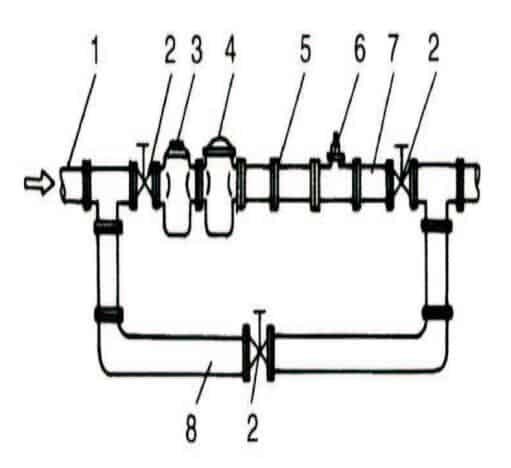
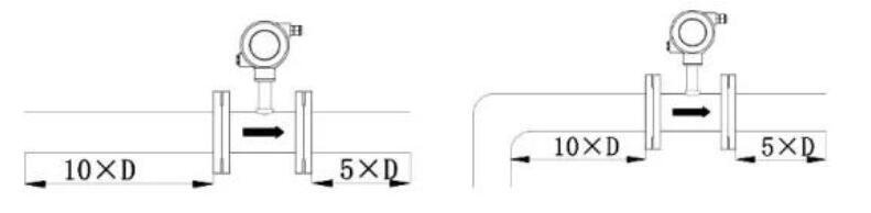
Turbine Flow Meter Installation Guidelines and Troubleshooting is compiled based on our Sino-Inst’s many years of experience in producing and supplying turbine flow meters. Whether it is a liquid turbine flow meter or a gas turbine flow meter. In order to ensure that the measurement of the turbine flowmeter is accurate. The installation location and installation precautions must be correctly selected.
The sensor should be installed in a place that is easy to maintain, has no vibration in the pipeline, and is not affected by strong electromagnetic interference and heat radiation.
A typical installation piping system for a turbine flowmeter is shown in the figure.
The configuration of each part in the figure depends on the situation of the measured object, not necessarily all of them.
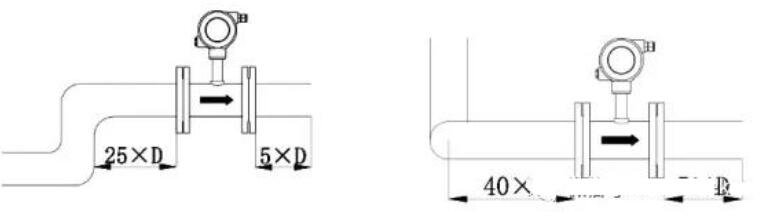
Turbine flowmeters are sensitive to distortion of flow velocity distribution and swirling flow in the pipeline, and the flow into the sensor should be fully developed. Therefore, the necessary straight pipe section or flow regulator should be equipped according to the type of choke on the upstream side of the sensor, as shown in the table below.
If the condition of the upstream side choke is not clear, it is generally recommended that the length of the upstream straight pipe section is not less than 20D, and the length of the downstream straight pipe section is not less than 5D. If the installation space cannot meet the above requirements, a flow regulator can be installed between the choke and the sensor.
When the sensor is installed outdoors, measures should be taken to avoid direct sunlight and rain.
Type of spoiler on the upstream side
Single 90° elbow
Two 90° elbows on the same plane
Two 90° elbows on different planes
Concentric reducer
Fully open valve
Hhalf open valve
Downstream side length
L/DN
20
25
40
15
20
50
5
Installation Requirements for Connecting Pipelines
The sensor installed horizontally requires that the pipeline should not have a visually detectable inclination (generally within 5°). The verticality deviation of the sensor pipe installed vertically should also be less than 5°. The fluid direction must be upward when installed vertically.
Where continuous operation is required and the flow cannot be stopped, bypass pipes and reliable stop valves should be installed. When measuring, make sure that there is no leakage in the bypass pipe.
In the position where the sensor is installed in the newly laid pipeline, a short pipe is first inserted to replace the sensor. After the “line sweeping” work is completed and the pipeline is cleaned, the sensor is formally connected. Due to neglect of this task, it is not uncommon for wire sweeping to damage the sensor.
If the fluid contains impurities, a filter should be installed on the upstream side of the sensor. For those that cannot stop the flow, two sets of filters should be installed in parallel to remove impurities in turn, or self-cleaning filters should be selected.
If the measured liquid contains gas, a muffler should be installed on the upstream side of the sensor. The sewage outlet and air elimination outlet of the filter and muffler should lead to a safe place.
If the installation position of the sensor is at the low point of the pipeline, in order to prevent the impurities in the fluid from settling and stagnating. A discharge valve should be installed in the subsequent pipeline to discharge the precipitated impurities regularly.
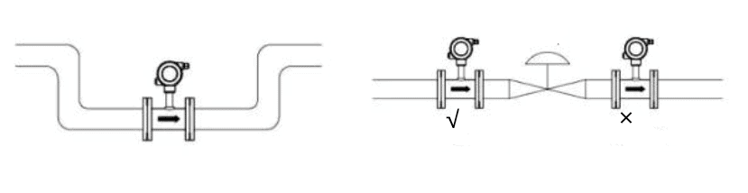
The flow regulating valve should be installed downstream of the sensor, and the stop valve on the upstream side should be fully open when measuring. And these valves must not produce vibration and leak outward. For processes that may generate reverse flow, check valves should be added to prevent reverse flow of fluid.
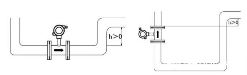
The sensor should be concentric with the pipe, and the sealing gasket should not protrude into the pipe. Liquid sensors should not be installed at the highest point of the horizontal pipeline. In order to prevent the gas accumulated in the pipeline (such as mixed gas when the flow is stopped) staying at the sensor, it is not easy to discharge and affect the measurement.
The pipelines before and after the sensor should be supported firmly without vibration. For condensable fluids, thermal insulation measures should be taken for the sensor and its front and rear pipelines.
Installation Requirements
The pipe must be completely filled with liquid. It is important to keep the tubing completely filled with fluid at all times. Otherwise the traffic display will be affected. Measurement errors may result.
Avoid air bubbles. If air bubbles enter the measuring tube, the flow display may be affected, possibly causing measurement errors.
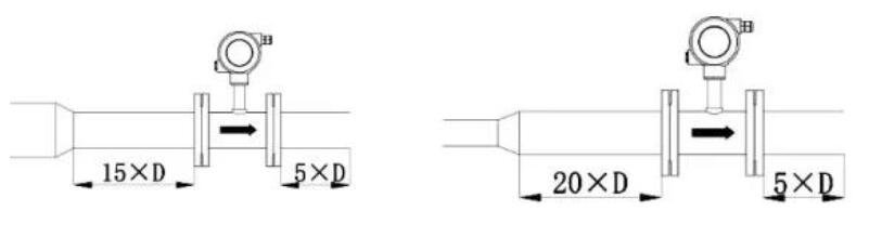
Straight pipe requirements
Generally
90° elbow
Two 90° elbows on the same plane
Two 90° elbows on different planes
shrink tube
Expansion
Fully open valve
half open valve
If the condition of the upstream side choke is not clear, it is generally recommended that the length of the upstream straight pipe section is not less than 20D, and the length of the downstream straight pipe section is not less than 5D.
If the installation control cannot meet the above requirements, a rectifier can be installed between the baffle and the sensor.
Gas Turbine Flow Meter Installation Guidelines
When installing the Gas Turbine Flow Meter, the user must carefully read the following content. Because the condition of the installation of the flowmeter directly affects the accuracy and life of the flowmeter, and even safety issues during work.
The installation work must be performed by personnel with corresponding pipeline equipment installation skills;
The flowmeter should be installed in a place that is convenient for maintenance, no strong electromagnetic field interference, no mechanical vibration and thermal radiation influence;
When the flowmeter is installed outdoors, there should be a cover on the upper part to prevent rainwater and hot sun from affecting the service life of the flowmeter;
When the flowmeter is installed, it is strictly forbidden to conduct electric welding directly at its inlet flange to avoid burning the internal parts of the flowmeter;
The newly installed or overhauled pipeline must be cleaned, and the flowmeter can be installed after removing the debris in the pipeline;
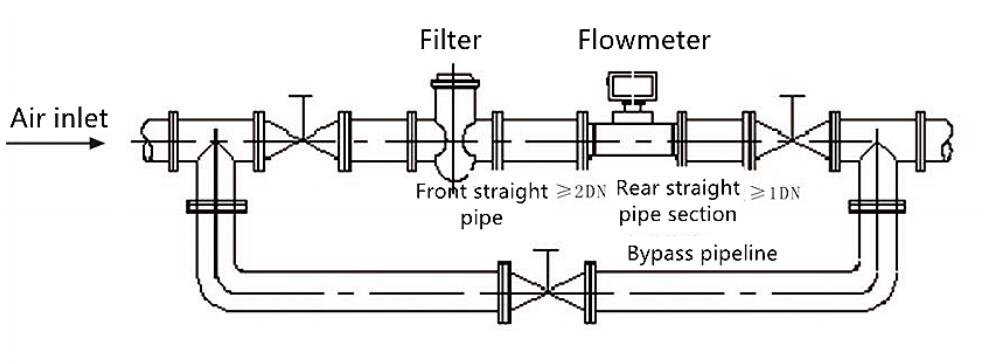
The flowmeter can only be installed horizontally, not vertically. The fluid flow direction should be consistent with the direction marked on the housing. There should be a straight pipe section ≥ 2DN upstream of the flowmeter, and a straight pipe section ≥ 1DN downstream of the flowmeter. Straight pipe section, and the filter of the corresponding specification must be installed at the upstream of the flowmeter (≥2DN) (the company can match) to prevent excessive particulate impurities in the pipeline from entering the flowmeter and affecting the service life of the meter;
The flowmeter should not be used in occasions where the flow is frequently interrupted and there is a strong pulsating flow or pressure pulsation;
Ensure that the connection between the pipeline and the inlet and outlet of the flowmeter is coaxial, and prevent gaskets and welds from protruding into the pipeline, otherwise the flow profile will be disturbed;
In order to facilitate the maintenance of the instrument, it is recommended to install the bypass pipeline according to Figure 6. Open the bypass when the instrument is maintained so as not to affect the normal production, and close the bypass pipeline during normal use.
When the flowmeter is put into operation, the upstream valve of the flowmeter should be slowly opened, and then the downstream valve of the flowmeter should be slowly opened, so as to avoid the instantaneous air flow that will destroy the turbine flowmeter;
The flowmeter must be reliably grounded as specified, but must not share the ground wire with the strong current system; during pipeline installation or maintenance, the ground wire of the electric welding system must not be overlapped with the flowmeter;
During use, users are not allowed to change the connection method of the explosion-proof system and change the lead interface arbitrarily;
1. There is no display when the liquid flows normally, and the cumulative volume does not increase
1) The power supply circuit or signal circuit is disconnected or poorly connected. Troubleshooting method: check with a multimeter to eliminate the fault point;
2) The printed circuit board of the display instrument, the connector is faulty or the contact is poor. Remedy: replace the printed circuit board;
3) The preamplifier is faulty. Troubleshooting method: Use an iron bar to move quickly under the detection head, if there is no signal output, check whether the coil is disconnected or the solder joint is desoldered;
4) The voltage supplied to the preamplifier is too low. Troubleshooting method: increase the power supply voltage to the specified requirements;
5) The impeller is stuck and does not rotate. Troubleshooting method: remove foreign matter, and clean or replace damaged parts, and re-calibrate after replacing parts;
2. When the flow is zero, the flow display is not zero, and the displayed value is unstable
1) Poor shielding and grounding of the transmission line, interference from the external electromagnetic field. Troubleshooting method: check the grounding and eliminate interference;
2) The pipeline vibrates, causing the impeller to vibrate. Troubleshooting method: strengthen the pipeline or install brackets before and after the flowmeter;
3) The shut-off valve is leaking. Troubleshooting method: overhaul or replace the valve;
4) Interference between circuit boards or electronic components inside the display is deteriorated and damaged. Troubleshooting method: take short circuit method”” or check one by one to find out the fault point;”
3. The displayed traffic does not match the actual traffic
1) The impeller is corroded and the blades are deformed. Troubleshooting method: Repair the impeller or re-calibrate after replacement;
2) The sundries hinder the rotation of the impeller. Troubleshooting: Clearing Debris;
3) The output signal of the detection coil is abnormal. Troubleshooting method: check the coil insulation resistance and conduction resistance;
4) The bypass valve is leaking. Troubleshooting method: close the bypass valve and replace it if necessary;
5) The flow velocity distribution upstream of the flowmeter is distorted or pulsating flow occurs. Troubleshooting method: find out the cause of distortion or pulsating flow, and take measures to eliminate it;
Sea Water Flow Measurement is becoming more and more important to many industries. Seawater can be directly used as production water in printing and dyeing, pharmaceutical, alkali making, rubber and…
High pressure rotameter is suitable for flow measurement of high pressure liquid and gas.Standard type rotameter: DN15-DN50, can withstand 4.0MPa. High pressure rotameter: DN15-DN50, can withstand 25MPa. The pressure level…
Mechanical diesel flow meter is a volumetric meter for continuous or intermittent measurement and control of diesel or other liquid flow in pipelines. It has many advantages such as large…
Are high pressure flow meters the same as regular flow meters? Can high pressure flow meters be replaced by ordinary flow meters?Of course not. You need to measure the flow…
What is Metal Tube Flow Meter? LZ series metal tube flow meter, also known as metal rotor flowmeter. Metal tube flow meter consists of a measuring tube and side indicator,…
Flow Pressure Transducers are measurements of fluid pressure within a pipeline. When fluid flows through a pipe, pressure acts on the pipe wall. The medium in the pipeline can be…
What is an insertion flow meter? Insertion flowmeter is a type of flowmeter in which the measuring probe is inserted into the pipe to measure the flow. This is a…
Crude Oil Flow Meter refers to a type of flow meter that can accurately monitor and measure the flow of crude oil. Crude oil is an industrial raw material with…
Sino-Inst, Manufacuturer for Turbine Flow Meters, like: gas turbine flow meter, liquid turbine flow meter, sanitary turbine flow meter, insertion turbine flow meter, steam turbine flow meter, and natural gas turbine flow meter.
Sino-Inst’s Turbine Flow Meters, made in China, Having good Quality, With better price. Our flow measurement instruments are widely used in China, India, Pakistan, US, and other countries.
If you have any questions about Turbine Flow Meter Installation Guidelines and Troubleshooting, please feel free to contact us.
Request a Quote
Please enable JavaScript in your browser to submit the form
Wu Peng, born in 1980, is a highly respected and accomplished male engineer with extensive experience in the field of automation. With over 20 years of industry experience, Wu has made significant contributions to both academia and engineering projects.
Throughout his career, Wu Peng has participated in numerous national and international engineering projects. Some of his most notable projects include the development of an intelligent control system for oil refineries, the design of a cutting-edge distributed control system for petrochemical plants, and the optimization of control algorithms for natural gas pipelines.
As a clean energy, natural gas is widely used in many aspects such as industrial production, thermal power generation and residential gas heating.
Although natural gas pipeline transportation has many advantages, there are also risks such as leakage and failure. This can lead to interruptions or leaks in the delivery, causing significant financial losses and further safety risks. Therefore, sensors and data acquisition equipment are used for monitoring to achieve the purpose of leakage prevention and failure prevention. At the same time, risk issues such as distributed gas quality and consumption balance are monitored.
In the entire gas pipeline monitoring system, the detection of pressure-temperature-flow ensures operation, thereby preventing gas interruption.
In the oil and gas sector, pressure sensors are fundamental components for a wide range of applications. The pressure sensor can be used to monitor the pipeline pressure in real time. Not only that, the pressure sensor is also used in the gas furnace to measure the pressure of the gas in the gas supply pipeline, so as to judge whether the gas is sufficient or whether it is leaking.
Pressure transmitters play an important role in moving natural gas through thousands of natural gas pipelines. For monitoring natural gas pressure, measuring very low inlet and outlet pressures;
Various pressure types are also involved in the measurement process. Such as gauge pressure, absolute pressure, differential pressure, high pressure and differential pressure, etc.;
Special approval options such as ATEX Intrinsic Safety are available where natural gas may be present in the local atmosphere;
Leaks and even explosions may occur if the gas pressure in gas and gas pipelines is too high;
If the air pressure is too low, it will affect people’s daily use. Therefore, it is necessary to monitor the air pressure of each node through the pressure sensor, so that the air pressure is within a reasonable range;
The gas pipeline pressure sensor generally adopts the threaded installation form, which is simple and convenient and easy to ensure the sealing of the product. The signal output of the gas pipeline pressure sensor has analog signal and digital signal, which belong to the remote transmission type signal.
Sino-Inst’s pressure transmitter can be matched with industrial control system PLC or configuration system to ensure the accuracy and reliability of the automation system. The most important thing to choose a gas pipeline pressure sensor is to consider the quality of the product. The Sino-Inst gas pipeline pressure sensor is made of a corrosion-resistant pressure core and a stainless steel outer protective shell thread to ensure the durability of the product. The signal expansion transmitter also uses imported electronic components to ensure the stability of the gas pipeline pressure sensor.
Regardless of oil drilling, extraction, or transportation, there are various challenges and difficulties in the application of pressure sensors in the oil and gas industry. For example, key issues such as cost control, safe construction and environmental protection. Our engineers have rich practical experience in this industry, can fully understand the problems and difficulties you actually encounter in the oil and gas industry, and provide you with pressure measurement solutions based on your needs, combined with our own technology.
General-purpose temperature transmitter, suitable for temperature measurement of gas or liquid, such as air, natural gas, steam, water or engine oil and other non-corrosive media. At the same time, a variety of analog and digital signal outputs are available for selection. It is convenient for users to form a measurement and control system with other equipment.
The temperature transmitter is based on a standardized Pt100 or Pt1000 temperature sensing element, providing customers with accurate and stable temperature measurement. The product is cost-effective and can meet various application requirements. It is an ideal product for temperature measurement.
In addition to gas pressure detection, we also provide Industrial Gas Measurement with Digital Gas Mass Flow Meters.
The flow measurement of natural gas is currently mainly used in trade settlement and is relatively common. my country’s natural gas trade measurement is based on the volume or energy method under the legally required quality indicators for transfer measurement. At this stage, volume measurement is basically the main method.
At present, the flowmeter products used for natural gas flow measurement generally include: gas waist wheel flowmeter, gas turbine flowmeter, precession vortex flowmeter, vortex flowmeter, ultrasonic flowmeter and orifice flowmeter.
Let’s make a simple comparison on the use of these flow meters.
What is a gas pressure sensor? Gas Pressure Sensors are also called Gas Pressure Transducers. Gas Pressure Sensors convert gas pressure into standard electrical signals, such as 4~20mADC. Measurement, indication…
High pressure rotameter is suitable for flow measurement of high pressure liquid and gas.Standard type rotameter: DN15-DN50, can withstand 4.0MPa. High pressure rotameter: DN15-DN50, can withstand 25MPa. The pressure level…
Are high pressure flow meters the same as regular flow meters? Can high pressure flow meters be replaced by ordinary flow meters?Of course not. You need to measure the flow…
In the new era, petrochemical enterprises are facing unprecedented challenges. How to improve the production efficiency of the petroleum industry and improve the product quality is an important problem that…
A kerosene flow meter is a flow meter that can be used to measure the flow of kerosene. Kerosene is a common oil in industrial production. It is an organic…
What is Digital Flow Meter for Argon Gas? Digital flow meter for argon gas refers to a flow meter that can be used for detection, display, transmission, and signal output…
What is Gas Rotameter? Rotameter is also called float flowmeter. It is often called glass tube float flowmeter, glass rotameter, metal rotameter, and metal tube float flowmeter.Rotameter is mainly used…
The gas mass flow controller is based on the principle of thermal mass flow measurement. With control valve. The Micro Gas Flow Controller (MFC) is used to precisely measure and…
Sino-Inst offers a variety of Digital gas flow meters for flow measurement. If you have any questions, please contact our sales engineers. Featured Digital gas flow meters for Sale Are…
In the entire gas pipeline monitoring system, the detection of pressure-temperature-flow is to ensure correct operation, thereby preventing gas interruption.
For the above characteristics, Sino-Inst provides high precision, good stability, low power consumption, easy to connect and supports customized pressure sensors, temperature sensors, flow meters, etc. Provide reliable pressure, temperature and flow monitoring support for gas pipeline monitoring.
Request a Quote
Please enable JavaScript in your browser to submit the form
Wu Peng, born in 1980, is a highly respected and accomplished male engineer with extensive experience in the field of automation. With over 20 years of industry experience, Wu has made significant contributions to both academia and engineering projects.
Throughout his career, Wu Peng has participated in numerous national and international engineering projects. Some of his most notable projects include the development of an intelligent control system for oil refineries, the design of a cutting-edge distributed control system for petrochemical plants, and the optimization of control algorithms for natural gas pipelines.
Different Types of Pressure have different characteristics. Different pressure transmitters bear different pressure types. Common pressure types include absolute pressure, gauge pressure, negative pressure or vacuum, and differential pressure.
Each type of pressure works and causes differently. Therefore, when selecting, installing and using pressure transmitters, different types of pressure transmitters should be selected according to the specific pressure. At the same time, when measuring, it is necessary to have a detailed understanding of the specific specifications of the pressure transmitter.
Gauge pressure is also called relative pressure. It is usually represented by “G”, and its reference point is atmospheric pressure. That is, the output point of the sensor is zero when the atmosphere is open. It can also be considered that the sensor does not consider the influence of atmospheric pressure on its measurement .
The sealed gauge pressure is usually represented by “S”. The sensor of the sealed gauge pressure uses an absolute pressure chip. However, when the output is calibrated, it is calibrated according to the output of the gauge pressure.
Absolute pressure is also called absolute pressure. It is represented by capital letter “A”. Its reference point is vacuum;
It is generally used to measure working conditions that may generate negative pressure. The absolute pressure gauge should display 102Kpa when it is not in use, which is the local atmospheric pressure.
Differential pressure: As the name implies, it refers to the difference between two pressures. That is, the difference between the pressure on the positive pressure end of the sensor and the pressure on the negative pressure end.
So what are the practical applications of these pressures?
Gauge pressure is usually used to measure without considering the influence of atmospheric pressure. For example, gauge pressure sensors are used in submersible liquid level transmitters.
Absolute pressure is just the opposite. Because its reference point is vacuum pressure. Many customers will choose absolute pressure sensors when measuring pipeline pressure.
Sealed gauge pressure is rarely used in practical applications. For diffused silicon pressure sensors, some customers will choose sealed gauge pressure in the scene of high humidity measurement. The purpose is to prevent water vapor from entering from the air hole behind the pressure core Pressure chip. This causes the instability of the output of the pressure chip. The failure phenomenon that often occurs in the use of sealed gauge pressure is that if there is a large difference between the atmospheric pressure at the sensor calibration location and the sensor user’s use location, the zero output of the sensor will appear A certain deviation. As a result, the accuracy deteriorates.
Differential pressure measures the difference between two pressures. So many customers use differential pressure to measure flow.
How to choose the pressure type?
Like temperature and Flow, pressure is one of the most important physical state variables. The different types of pressure are mainly distinguished based on the reference pressure. When measuring the pressure of liquid or gaseous media, the pressure type and pressure range are important factors for pressure transmitters.
Pressure range: such as ≤0.02MPa, ≥3.5MPa, 0.035MPa~3.5MPa.
In layman’s terms, ordinary pressure gauges measure gauge pressure. Adding atmospheric pressure is absolute pressure, and there is a special absolute pressure gauge for measuring absolute pressure.
The pressure is taken at two different locations on the pipeline, and the difference between the two pressures is the differential pressure. The general differential pressure transmitter is to measure the differential pressure.
The sealing pressure is a pressure that is sealed in the back pressure chamber of the sensor as a reference pressure.
As atmospheric pressure may vary with location, weather and altitude. Therefore specific applications require different pressure types.
Whether it is absolute pressure, gauge pressure or differential pressure. If you are not sure which to choose. Our experienced and professional sales engineers are happy to assist you.
The pressure transmitter is the so-called universal gauge pressure transmitter. One side is open to the atmosphere and the other side is connected to the measured pressure. It is used to measure the pressure of pipelines, boilers, etc. The pressure transmitter has only one impulse tube and measures pure pressure.
The differential pressure transmitter has two pressure pipes and measures the pressure difference. If the differential pressure transmitter is only connected to the positive membrane chamber or the negative membrane chamber, it is equivalent to the measurement of the pressure transmitter. The two sides of the differential pressure transmitter are respectively connected to different pressures. Measure the height of the liquid level according to the pressure difference and cooperate with the orifice plate to measure the flow of the pipeline.
One side of the absolute pressure transmitter is evacuated, and the pressure on the other side is absolute pressure. Suitable for absolute pressure applications.
The Micro differential pressure transmitter uses 2E capsule (0.0-1.5KPA) to improve the accuracy of measuring small pressure.
The high static pressure differential pressure transmitter uses a high static pressure capsule. The so-called static pressure means that when the pressure on both sides of the pressure transmitter is the same, its output current should be 4.00MA. However, when the pressure on both sides of the ordinary differential pressure transmitter increases to more than 25MPA at the same time, it is difficult to guarantee the output at 4.00MA. Therefore, high static pressure differential pressure transmitters are mostly used for flow, liquid level measurement and high pressure occasions.
What else can a pressure transmitter measure?
Liquid Level
Pressure transmitters and differential pressure transmitters measure pressure and differential pressure (the difference between the two pressures) by name. But they can be measured indirectly by a lot. In addition to measuring pressure, it can also measure the liquid level in the equipment.
When measuring the liquid level in an atmospheric pressure vessel, a pressure transmitter is all that is needed. When measuring the liquid level of a pressure vessel, consider using two pressure/differential pressure transmitters. That is, one set for the lower limit of measurement and one set for the upper limit of measurement. They have to output signals for subtraction. The liquid level can be measured.
Density
It can also be used to measure the density of the medium when the liquid level and pressure in the container do not change.
Flow
The measuring range of the pressure transmitter can be made very wide. Starting from absolute pressure 0, it can reach more than 100 MPa (general situation). In addition to measuring the differential pressure value of the two measured pressures, the differential pressure transmitter. It can also cooperate with various throttling components to measure the flow rate of medium fluid.
The static pressure sensor or static pressure transmitter is based on atmospheric pressure or absolute vacuum, and compares the difference between the measured pressure and atmospheric pressure or absolute vacuum…
Ship Ballast Tank is to point to the ship’s ballast tank to load ballast to adjust the ship’s draft and metacentric height. It is an operation to ensure that the…
Do you know the difference between Pressure Transmitter vs Pressure Gauge? Pressure transmitters and pressure gauges are industrial process instruments used to measure the pressure of media.Understanding the difference between…
Pressure Transmitter 4-20mA is the most commonly used one in industrial process control. In industrial process control, the measurement and control of pressure has always been a very important parameter…
What is a gas pressure sensor? Gas Pressure Sensors are also called Gas Pressure Transducers. Gas Pressure Sensors convert gas pressure into standard electrical signals, such as 4~20mADC. Measurement, indication…
Water Pressure Sensors Water Pressure Sensors refers specifically to instruments used to measure the pressure of tanks, pipes or underground water. Also called Water Pressure Transducers, or Water Pressure transmitters…
Flow Pressure Transducers are measurements of fluid pressure within a pipeline. When fluid flows through a pipe, pressure acts on the pipe wall. The medium in the pipeline can be…
After the Pressure Transducer is installed, how should I wire it? Pressure sensor wiring refers to the electrical connection of the pressure sensor. A pressure transmitter is a conversion device…
High Accuracy Pressure Transducers are also called high precision pressure transducers or high accuracy pressure sensors. Sino-Inst manufactures various types of High Accuracy Pressure Transducers. From the perspective of accuracy,…
Flat Pressure Sensor is a type of pressure sensor that specifically refers to the measurement diaphragm without pressure holes. Also known as a flat film pressure sensor. Flat Pressure Sensor…
Sino-Inst is a manufacturer of Different Types of Pressure Transmitters. We supply more than 50 types of Differential Pressure Transmitters. 30% are gauge pressure transmitters, 30% are differential pressure transmitters, and the rest are absolute pressure and other types pressure transmitter.
The concept of differential types of pressure is involved in the selection of pressure transmitters: absolute pressure, gauge pressure, negative pressure and differential pressure.
Although their explanations are somewhat difficult to understand, the principle is actually very simple. You only need to know this, the principle of these four pressure transmitters is the principle of differential pressure. That is, one side is connected to the medium pressure, and the other side is the reference pressure. The only difference is the pressure at the connection on the reference pressure side.
Sino-Inst has provided Different Types of Pressure measurement solutions to customers for many years. Our Different Types of Pressure Transmitters, made in China. Widely exported to the United States, Britain, Germany, South Africa, Norway and other countries.
If you need Different Types of Pressure Transmitters, but have technical questions, please feel free to contact our sales engineers.
Request a Quote
Please enable JavaScript in your browser to submit the form
Wu Peng, born in 1980, is a highly respected and accomplished male engineer with extensive experience in the field of automation. With over 20 years of industry experience, Wu has made significant contributions to both academia and engineering projects.
Throughout his career, Wu Peng has participated in numerous national and international engineering projects. Some of his most notable projects include the development of an intelligent control system for oil refineries, the design of a cutting-edge distributed control system for petrochemical plants, and the optimization of control algorithms for natural gas pipelines.
The static pressure sensor or static pressure transmitter is based on atmospheric pressure or absolute vacuum, and compares the difference between the measured pressure and atmospheric pressure or absolute vacuum.
The application of Static Pressure Sensors and Transmitter in industry is not only to measure the pressure of pipelines or tanks, but also to measure liquid level. Let’s look at it in detail below.
Static pressure sensors are often used to measure static air pressure. Such as the static pressure on air filters and cooling coils, the input and discharge pressure of blowers, etc.
In ventilation systems, static pressure is the pressure of the air inside the building relative to the air outside when the exhaust fans are turned on. Measuring and maintaining proper negative pressure allows ventilation systems to more effectively mix outside air with inside air.
Types
Diaphragm pressure sensors are based on the structure of the sensor. According to the sensing principle, diaphragm pressure sensors can be divided into different types such as piezoresistive, strain gauge, inductive, capacitive, and piezoelectric.
Among the above-mentioned pressure sensors with different principles, piezoelectric pressure sensors are only suitable for measuring dynamic pressure, so dynamic calibration is required;
Other dynamic and static pressures can be measured, and the most widely used one belongs to the quasi-static measurement with very low frequency. Therefore, static calibration is the most widely used calibration form. When the measured pressure frequency band is wide, all kinds of pressure sensors should be calibrated for frequency response.
Hydrostatic level transmitters are based on the principle that the measured static pressure of a liquid is proportional to the height of the liquid. A device that converts static pressure into electrical signals by using the piezoresistive effect of diffused silicon or ceramic sensitive elements.
After temperature compensation and linear correction, it is converted into 4-20mADC standard current signal output.
The sensor part of the submersible static pressure liquid level transmitter can be directly put into the liquid. The transmitter part can be fixed by flange or bracket, which is very convenient to install and use.
For deep well level measurement, especially deep wells, we recommend submersible hydrostatic level transmitters.
The submersible hydrostatic pressure level transmitter is based on the principle of hydrostatics, which is converted into liquid level height through the measurement of liquid pressure. Fully sealed submerged measurement, integrated structure and standardized output signal. It provides convenience for on-site use and automatic control.
Then through reasonable selection and design of liquid-wetted materials, cables, protective tubes, etc. The liquid level of different media can be measured. It is suitable for deep mine liquid level measurement, groundwater level, hydrological detection, long-term underwater measurement of reservoirs, rivers, oceans, etc.
It is very important to ensure the full water level of the fire water tank and the high fire water tank, and to be able to monitor remotely in the fire control room.
Using the drop-in water level sensor, the water level probe is directly put into the bottom of the fire pool or water tank. In the fire control center, the real-time water level of the fire water tank can be monitored in real time. It also has a high and low liquid level alarm function to ensure that the fire water tank operates at a full water level.
Sino-Inst offers reliable pressure transmitter, level transmitter, and flowmeters for fire water tank/water treatment monitoring applications. Such as water management, sewage treatment, water purification treatment, etc.
High Temperature Pressure Sensor is used in industrial fields such as water plants, oil refineries, sewage treatment plants, building materials, light industry, machinery, etc. to achieve the measurement of liquid, gas and vapor pressure.
Cryogenic pressure transducer has small size, high measurement accuracy, high dynamic response frequency, strong corrosion resistance and long working life.
Our professional technical group provides you with customized services. This product is mainly used for: low temperature scientific experiment, liquid Oxygen, liquid nitrogen, liquid hydrogen, liquid helium, etc. Pressure and low temperature measurement of cooling tanks, cryogenic storage tanks, propellants, etc. Cryogenic storage tanks for aerospace, aviation, naval vessels, etc.
Most of our liquid level sensors can output liquid level signals, such as 4-20mA signal, 0-10V signal, RS485 and so on.
However, the liquid level transmitter alone cannot calculate the liquid volume of tanks of different sizes. It’s too complicated. A separate recorder is required to calculate it.
Therefore, the digital display volume meter can collect, display and convert the liquid level of various regular and irregular tanks in the industrial field into the corresponding tank volume. It is suitable for monitoring, controlling and collecting various process parameters.
Ship Ballast Tank is to point to the ship’s ballast tank to load ballast to adjust the ship’s draft and metacentric height. It is an operation to ensure that the…
Do you know the difference between Pressure Transmitter vs Pressure Gauge? Pressure transmitters and pressure gauges are industrial process instruments used to measure the pressure of media.Understanding the difference between…
Pressure Transmitter 4-20mA is the most commonly used one in industrial process control. In industrial process control, the measurement and control of pressure has always been a very important parameter…
What is a gas pressure sensor? Gas Pressure Sensors are also called Gas Pressure Transducers. Gas Pressure Sensors convert gas pressure into standard electrical signals, such as 4~20mADC. Measurement, indication…
Water Pressure Sensors Water Pressure Sensors refers specifically to instruments used to measure the pressure of tanks, pipes or underground water. Also called Water Pressure Transducers, or Water Pressure transmitters…
Pressure Sensor Applications refer to industrial pressure transmitters that convert gas, liquid and other pressure parameters into standard electrical signals (such as 4~20mADC, etc.). For on-site or remote measurement and…
Flow Pressure Transducers are measurements of fluid pressure within a pipeline. When fluid flows through a pipe, pressure acts on the pipe wall. The medium in the pipeline can be…
After the Pressure Transducer is installed, how should I wire it? Pressure sensor wiring refers to the electrical connection of the pressure sensor. A pressure transmitter is a conversion device…
Sino-Inst is a manufacturer of Static Pressure Sensor and Transmitters. We offer more than 50 types of pressure sensors. Main products include compact pressure transmitters, industrial pressure transmitters, differential pressure transmitters, single pressure crystal silicon transmittance pressure transmitters, diff pressure transmitter, high temperature pressure transmitter, explosion-proof pressure transmitter, pressure transmitter, custom pressure transmitter, with remote pressure transmitter, 316 diaphragm pressure transmitter.
The static pressure sensor or static pressure transmitter is based on atmospheric pressure or absolute vacuum, and compares the difference between the measured pressure and atmospheric pressure or absolute vacuum.
For static, slowly changing pressure measurement. The sensor usually uses a high stability, thin film piezoresistive sensing element. The stability of the sensor and the accuracy of the measurement can meet the requirements of the industrial control field. There are a variety of connectors, electronic connections, signal output formats, accuracy and a wide range of ranges to choose from. These components are an ideal match for process monitoring and control, liquid level measurement, hydraulic system test studies and test cell requirements.
Sino-Inst’s entire team is well trained, so we can ensure that each customer’s needs are met. If you need any help with your product requirements, whether it is a Static Pressure Sensor and Transmitter, level sensors, or other equipment, please give us a call.
Request a Quote
Please enable JavaScript in your browser to submit the form
Wu Peng, born in 1980, is a highly respected and accomplished male engineer with extensive experience in the field of automation. With over 20 years of industry experience, Wu has made significant contributions to both academia and engineering projects.
Throughout his career, Wu Peng has participated in numerous national and international engineering projects. Some of his most notable projects include the development of an intelligent control system for oil refineries, the design of a cutting-edge distributed control system for petrochemical plants, and the optimization of control algorithms for natural gas pipelines.
Ship Ballast Tank is to point to the ship’s ballast tank to load ballast to adjust the ship’s draft and metacentric height. It is an operation to ensure that the ship has good seaworthiness. Water is commonly used as ballast.
In bulk cargo transportation, since the cargo flow is usually one-way, the ship has to sail for a long distance without a load. In order to obtain the necessary draft to ensure the efficiency of the propeller and to obtain the necessary metacentric height to ensure safety. The ship must be loaded with a large number of of ballast water.
Ballast water is critical to the safe and efficient operation of shipping. Wing and double bottom tank ballast water level measurement is used to control trim, draft and heel of ships, reduce hull deformation and improve empty space seaworthiness.
At the same time, ballast water poses a serious threat to marine ecology, economy and public health. In order to protect the ecological environment, protect public health and property safety. According to the International Maritime Organization regulations, ships must be equipped with ballast water treatment equipment.
The ship ballast water system varies according to the type, purpose and tonnage of the ship. The location, size and number of ballast water tanks on the ship also vary. Generally, ships can use the fore peak tank, stern peak tank, double bottom tank, side tank, top side tank and deep tank as ballast water tanks, and cargo oil tankers can use cargo oil tank and ballast tank.
There are three types of pipeline layout for ship ballast water system: branch pipe type, main pipe type and pipe tunnel type;
The suction pipe in the ship’s ballast water tank should also have the function of adding water;
The ballast suction port of each ballast water tank shall be arranged at a position conducive to the discharge of ballast water;
In order to meet the working characteristics of the ballast water system and simplify the pipeline. The barge valve box is often used to adjust the ballast water in each ballast water tank;
The ship’s ballast water system shall be able to transfer the ballast water in and out of each ballast tank of the whole ship or transfer each other. Also can not use ballast pump, outboard seawater flows into ballast water tank automatically by pressure difference.
There are many types of ballast water management systems, all of which require measurement of incoming water flow, tank level and system pressure for control purposes. Since these instruments are essential, reliability and stability are an absolute must.
In addition to ballast water systems, Sino-Inst can also provide professional monitoring solutions for different systems such as water circulation cooling systems, ship water supply and ship sewage treatment.
A pressure transducer (Pressure Transducer) is a device or device that can sense pressure signals and convert the pressure signals into usable output electrical signals according to certain rules.
A pressure sensor usually consists of a pressure sensitive element and a signal processing unit. According to different test pressure types, pressure sensors can be divided into gauge pressure sensors, differential pressure sensors and absolute pressure sensors.
Pressure sensor is the most commonly used sensor in industrial practice. It is widely used in various industrial automatic control environments, involving water conservancy and hydropower, railway transportation, intelligent buildings, production automatic control, aerospace, military industry, petrochemical, oil wells, electric power, ships, machine tools , pipeline and many other industries.
The first type of pressure sensor commonly used on ships is the pressure sensor that measures the pressure of pipes and tanks. Pressure measurement for ships and other long-term operations in relatively harsh environments such as seawater and river water.
The sensor has a solid measuring element, which is not afraid of the influence of marine microorganisms, sediment, etc. on the sensor. IP68 protection level, 316L, titanium alloy outer shell, can work stably and reliably for a long time. It is widely used in the fields of ship ballast tank, ship boiler liquid level, pressure and other fields. It can simplify measurement and improve work efficiency.
Ballast water (ballast water) is water specially injected to keep a ship balanced. Ballast water is an important guarantee for the safe navigation of a ship, especially for a ship that does not carry an appropriate amount of cargo. An appropriate amount of ballast water can ensure sufficient draft of the ship’s propeller, minimize the shaking of the ship’s hull caused by the ship’s wake, and maintain propulsion efficiency.
Corrosion-resistant contact liquid level meters and non-contact liquid level meters can be used on ships to provide effective monitoring for Ship Ballast Tank liquid level management.
Do you know the difference between Pressure Transmitter vs Pressure Gauge? Pressure transmitters and pressure gauges are industrial process instruments used to measure the pressure of media.Understanding the difference between…
Pressure Transmitter 4-20mA is the most commonly used one in industrial process control. In industrial process control, the measurement and control of pressure has always been a very important parameter…
What is a gas pressure sensor? Gas Pressure Sensors are also called Gas Pressure Transducers. Gas Pressure Sensors convert gas pressure into standard electrical signals, such as 4~20mADC. Measurement, indication…
Water Pressure Sensors Water Pressure Sensors refers specifically to instruments used to measure the pressure of tanks, pipes or underground water. Also called Water Pressure Transducers, or Water Pressure transmitters…
Pressure Sensor Applications refer to industrial pressure transmitters that convert gas, liquid and other pressure parameters into standard electrical signals (such as 4~20mADC, etc.). For on-site or remote measurement and…
Crude oil measurement is important to the petrochemical industry. To control costs and improve efficiency. Effective crude oil level measurement regulation has become a challenge for many plants. If you’re…
Sludge Blanket Level Detectors use ultrasonic technology, so they are also known as ultrasonic mud level meters. Ultrasonic Sludge Blanket Level Detector uses ultrasonic emission with echo analysis of solids…
Diesel Level Sensors are used in Fuel Tank\Oil Depot. By accurately measuring the level data of the oil tank, it can effectively manage the inflow, sale and storage of oil…
Ultrasonic level sensor for diesel tank includes top mount and external mount. Oil tanks are storage equipment commonly used in oil depots, oil terminals, oilfield refineries and petrochemical enterprises. For…
Flow Pressure Transducers are measurements of fluid pressure within a pipeline. When fluid flows through a pipe, pressure acts on the pipe wall. The medium in the pipeline can be…
The Cryogenic Level Sensor is a capacitance-based level transmitter for cryogenic liquid level measurement. Cryogenic Level Sensor is a customized product for liquid level measurement in low temperature environments such…
Sino-Inst is a manufacturer of pressure sensors and liquid level sensors. We offer a wide range of transmitters for marine vessels (drilling platforms, ship ballast tanks, seawater pressure, seawater level).
If you have any technical questions, please feel free to contact our sales engineers.
Request a Quote
Please enable JavaScript in your browser to submit the form
Wu Peng, born in 1980, is a highly respected and accomplished male engineer with extensive experience in the field of automation. With over 20 years of industry experience, Wu has made significant contributions to both academia and engineering projects.
Throughout his career, Wu Peng has participated in numerous national and international engineering projects. Some of his most notable projects include the development of an intelligent control system for oil refineries, the design of a cutting-edge distributed control system for petrochemical plants, and the optimization of control algorithms for natural gas pipelines.
Sea Water Flow Measurement is becoming more and more important to many industries. Seawater can be directly used as production water in printing and dyeing, pharmaceutical, alkali making, rubber and seafood processing industries. Since seawater is widely used, the measurement and control of seawater flow is also crucial.
Sino-Inst supplies various sea water flow meters. Seawater is a kind of salt water, which is highly corrosive. Electromagnetic flowmeter and ultrasonic flowmeter are the most widely used in Sea Water Flow Measurement.
Seawater stores 96.54% of the earth’s fresh water, which contains a huge amount of minerals, energy and other resources. The current forms of seawater resources development and utilization mainly include: seawater desalination, direct utilization of seawater and utilization of seawater chemical resources.
In seawater desalination
In coastal cities and islands where water resources are seriously short. Mainly large-scale industrial seawater desalination projects. Mainly concentrated in high water consumption industries such as electric power and steel. Seawater desalination projects for islands used in offshore cities.
In terms of direct use of seawater
Mainly for seawater cooling applications. Among them, seawater DC cooling technology is mature and is mainly used in coastal thermal power, nuclear power, petrochemical, steel and other industries. Seawater circulating cooling technology has been gradually applied in the coastal power industry.
In the utilization of seawater chemical resources
It mainly includes salt production from seawater, potassium extraction from seawater, bromine extraction from seawater, magnesium extraction from seawater, etc. In addition to seawater salt production, the main products include bromine, potassium chloride, magnesium chloride, magnesium sulfate, and potassium sulfate.
Therefore, the utilization rate of seawater is getting higher and higher. Even in the future, people will find more favorable treatment and utilization of seawater. Among them, flow measurement before and after seawater treatment, or flow measurement before and after seawater use will become more and more important.
Difficulties in sea water measurement
Seawater is a highly corrosive fluid. Seawater is a very complex multi-component aqueous solution, which contains various ions such as sodium, potassium, calcium, magnesium, copper, zinc, manganese, etc. Its salt content is very high and it is highly corrosive.
Simultaneously, waves and tides create low-frequency mutual stress and impact metal parts. Marine microorganisms, attached organisms and their metabolites also produce direct or indirect accelerated corrosion processes.
Marine corrosion is mainly localized corrosion, which starts at the surface of the component and occurs in a small area. Examples include galvanic corrosion, pitting and crevice corrosion.
Therefore, it is very necessary to consider corrosion issues when selecting seawater flowmeter sensors.
Magnetic flowmeter to measure sea water
Electromagnetic flow is the preferred flowmeter for measuring the volume flow of liquids with a certain conductivity. Electromagnetic flowmeter is a flow measuring instrument that works based on the principle of electromagnetic induction. It consists of sensors and transmitters.
Advantages
There are no moving parts and bluff bodies in the measuring conduit. Therefore, the pressure loss is very small, and there is no mechanical inertia, so the response is sensitive;
Wide measurable range: the turndown ratio is generally 10:1, up to 100:1. The flow velocity range is generally 1-6m/s, and can be extended to 0.5-10m/s. The flow range can be from 90mL/h to hundreds of thousands of m3/h. Pipe diameters can range from 2mm to 2400mm or 3000mm.
It can measure the volume flow of liquids containing solid particles, suspended matter, or acids, alkalis, and salt solutions with certain conductivity. It can also measure pulsating flow, and can carry out two-way measurement.
There is a linear relationship between the flow signal and the fluid volume flow, so the meter has a uniform scale. And the volume flow rate of the fluid has nothing to do with the physical properties and flow state of the medium. Therefore, the electromagnetic flowmeter only needs to be calibrated with water, and it can be used to measure the volume flow of other conductive liquids without correction.
Compared with most other flow meters, the requirements for the front straight pipe section are lower.
Disadvantages
The temperature and pressure should not be too high;
The scope of application is limited. It cannot be used to measure the flow of non-conductive fluids such as gas, steam and petroleum products, and fluids containing more and larger bubbles;
When the flow rate and velocity distribution do not meet the set conditions, large measurement errors will occur;
When the flow rate is too low, it is difficult to amplify and measure the induced potential of the order of magnitude opposite to the interference signal. And the instrument is also prone to zero drift;
The signal of the electromagnetic flowmeter is relatively weak. A little interference from the outside world can affect the accuracy of the measurement.
Ultrasonic flowmeters are instruments that measure volume flow by detecting the action of ultrasonic beams (or ultrasonic pulses) when fluid flows.
The sound wave propagates in the fluid, and the sound wave propagation speed will increase in the downstream direction. , the countercurrent direction decreases, and the same propagation distance has different propagation times. The propagation time method is to calculate the flow velocity by using the relationship between the difference of the propagation velocity and the flow velocity of the measured liquid. Combined with the pipe diameter to obtain the flow rate.
Advantages
Ultrasonic flowmeter can be used for non-contact measurement. The clip-on transducer ultrasonic flowmeter can be installed without stopping the flow-carrying tube. Just install the transducer outside the pipeline to be tested. That is, the flow can be measured with an ultrasonic flowmeter on existing pipelines that cannot be cut off or drilled;
Ultrasonic flowmeters measure without flow obstruction. No additional pressure loss;
The instrument factor of the measuring meter can be calculated from the geometric dimensions of the actual measurement pipe and sound channel. The dry method can be used for calibration. Except for the type with measuring pipe section, it generally does not need to do real flow calibration;
The ultrasonic flowmeter in the propagation time method can only be used for clean liquids and gases, and cannot measure liquids with suspended particles and air bubbles exceeding a certain range. On the contrary, the Doppler method LSF can only be used to measure liquids containing certain heterogeneous phases;
Ultrasonic flowmeters with external transducers cannot be used in lined or heavily scaled pipes. And it cannot be used for stripping the lining (or rust layer) from the inner pipe. If there is gas in the interlayer, the ultrasonic signal will be seriously attenuated. Or pipes with severe corrosion (changing the ultrasonic path);
In most cases, the Doppler method ultrasonic flowmeter has a low measurement rate;
It cannot be used for pipes with a diameter smaller than DN15mm.
So, which flow meter should you choose for Sea Water Flow Measurement or salt water flow? We believe that:
If the seawater concentration is low and the salinity is small.
Then ultrasonic flowmeter is a better choice. Such flow meters do not require contact with seawater and avoid corrosion. At the same time, its flow sensor is not a metal part and is not afraid of corrosive materials.
For this type of seawater, if you choose an electromagnetic flowmeter. Then a 316L stainless steel electrode and rubber lining material should work well.
If the seawater has high concentration and high salinity.
Then the external clamp ultrasonic flowmeter is a better solution.
If you want to choose an online electromagnetic flowmeter for better performance. The best choice is Hastelloy C electrode and PTFE lining material. Hastelloy C electrodes are suitable for oxidation of salts such as Fe++, Cu++ and seawater.
For seawater desalination projects, plastic pipes are mainly used as water delivery equipment.
Many pipes are in the air. If an in-line electromagnetic flowmeter is used, the electromagnetic flowmeter is heavy. And the plastic tube doesn’t hold it in place very well. As a result, support brackets have to be installed, which adds a lot of cost and inconvenience.
Therefore, we recommend using a transit-time ultrasonic water flow meter. No pipe cutting required, light weight, easy installation, no maintenance etc.
If it is to measure the pipeline above DN3000.
Then the external clamp ultrasonic flowmeter is a better choice. For large diameter pipes, clamp-on ultrasonic flowmeters are less costly.
Water flow measurement is common in both industry and life. You may often hear about the use of electromagnetic flowmeters to measure wastewater. The clamp-on ultrasonic flowmeter measures large water…
What is BTU Meter for Chilled Water? The BTU Meter for Chilled Water accurately measures the thermal energy consumed by chilled water in British Thermal Units (BTU). This is a…
What is Clamp on Water Flow Meter? Clamp on Water Flow Meter is also known as the clamp-on ultrasonic flowmeter. Using an ultrasonic flowmeter to measure water flow rate is…
LORA Water Meter is a commonly used wireless water meter/wireless flowmeter. The wireless remote water meter measures the water flow in the pipeline. The microcomputer in the water meter automatically…
What is an irrigation flow meter? The irrigation flow meter is a flow meter designed for agricultural irrigation water counting. Agriculture, horticulture, etc. require water for irrigation. And water is…
Mechanical water flow meters refer to a type of flow meter suitable for clean water processes or applications. The working principle of a mechanical water flow meter is to measure…
The ultrasonic water flow meter is a meter that measures water flow by detecting the effect of water flow on ultrasonic beams (or ultrasonic pulses). The more commonly used methods…
What does a residential water meter look like? A residential water meter is a legal meter for measuring water consumption in residential communities, residential buildings, bungalows, and other places. What…
Application What is a Chilled Water Flow Meter? A chilled water flow meter refers to a flow meter that can be used to measure low-temperature water. Common chilled water flow…
Low cost 3″ Water Meter 3″ water meter is also DN80 water meter. Easy to read. Totalizing water volume. Intelligent large-caliber remote water meter includes wired remote transmission and wireless…
Featured inline water flow meters Strap on flow meter X3 External clamp-on flow sensor. Easy to install. Suitable for measuring pipe diameter Φ9.53~Φ90. Ultrasonic Water Meter for Residential Water DN15-DN40,…
Sino-Inst is a manufacturer of electromagnetic flowmeters and ultrasonic flowmeters. It has been used for sea water-salt water flow measurement for a long time.
Sino-Inst supplies more than 30 types of seawater flow meters for sea water flow measurement. 55% are electromagnetic flowmeters and 45% are ultrasonic flowmeters.
Electromagnetic flowmeters and ultrasonic flowmeters have their own advantages in Sea Water Flow Measurement. You can choose the appropriate model based on your measurement needs and cost budget.
Sino-Inst’s Sea Water Flow Measurement – Magnetic vs Ultrasonic Flowmeters are the most commonly used sensors in industrial applications. Widely used in water conservancy and hydropower, railway transportation, intelligent building, production control, aerospace, military chemicall, military industry, electric power, ship, machine tool, pipeline and other industries.
Sino-Inst’s entire team is well trained, so we can ensure that each customer’s needs are met. If you need any help with your product requirements, whether it is a Sea Water Flow Meter, level sensors, or other equipment, please give us a call.
Request a Quote
Please enable JavaScript in your browser to submit the form
Wu Peng, born in 1980, is a highly respected and accomplished male engineer with extensive experience in the field of automation. With over 20 years of industry experience, Wu has made significant contributions to both academia and engineering projects.
Throughout his career, Wu Peng has participated in numerous national and international engineering projects. Some of his most notable projects include the development of an intelligent control system for oil refineries, the design of a cutting-edge distributed control system for petrochemical plants, and the optimization of control algorithms for natural gas pipelines.