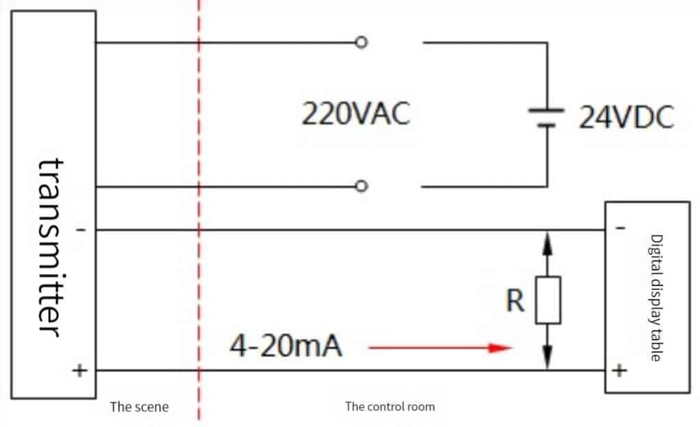
Are high pressure flow meters the same as regular flow meters? Can high pressure flow meters be replaced by ordinary flow meters?
Of course not.
You need to measure the flow of fluids under high pressure, but you’re not sure which type of flow meter is best for your application.
Choosing the right flow meter can be difficult, because there are so many different types available on the market. How do you know which one is right for your specific application?
Sino-Inst offers a wide range of high pressure flow meters that are specifically designed to operate in demanding applications. Our high pressure flowmeters are made from stainless steel construction and are ideal when measuring the flow of fluids under high pressures.


If you’re not sure which high pressure flow meter is right for your application, please contact us and we will be happy to help you select the best model for your needs.
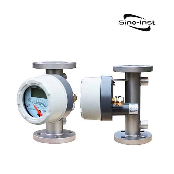
High Pressure Flow Meters Types
There are various types of high pressure flow meters available on the market including: positive displacement, turbine, magnetic, gear, coriolis mass flow meters. Each type of meter has its own advantages and disadvantages that should be considered when selecting a high pressure flow meter for a particular application. Read more about: Flow Meter Selection Guide
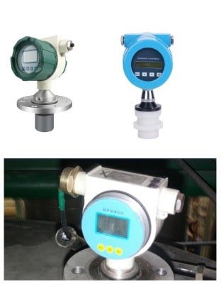
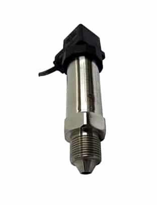
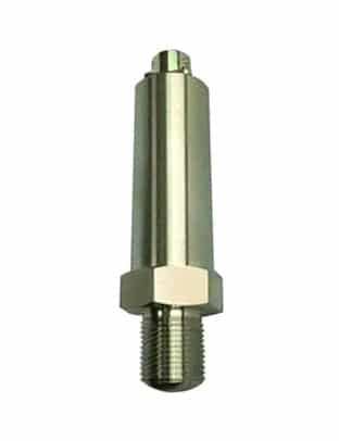
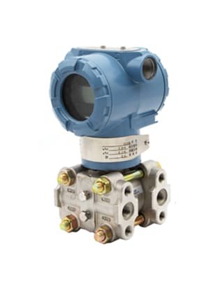
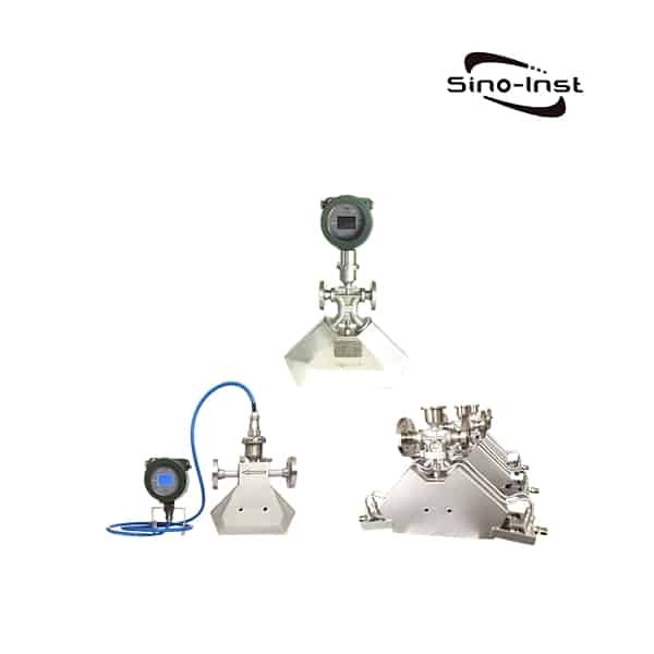
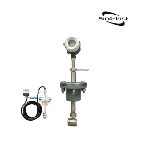
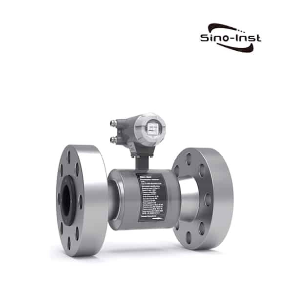
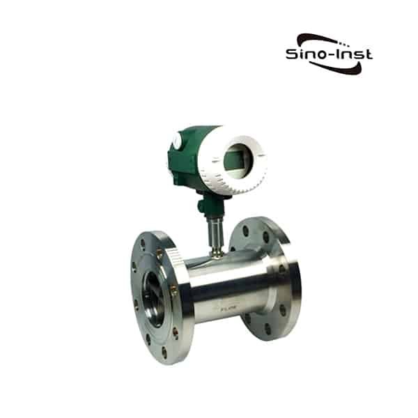
High pressure turbine flow meter is one of the most popular types of high pressure flow meters due to its high accuracy and repeatability. It is also relatively easy to install and maintain. High pressure turbine flow meters work by measuring the rotation of a turbine blade that is caused by the flow of fluid passing through the meter. It is the best choice for flow measurement of various high-pressure liquids and oils.

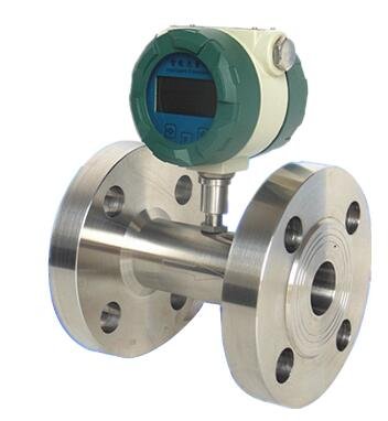
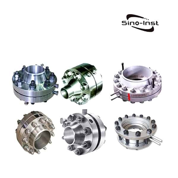
The housing is made of stainless steel. The meter has a simple structure and optimized structural design. High-pressure butt-weld flange clamping or high-pressure threaded connection structure is used.
- High pressure structure design, up to 40MPa.
- Advanced micro-power high-tech, low power consumption.
- new sensors, low initial flow and low pressure loss.
- High accuracy with good overlap
- multiple output modes for easy system integration.
Main applications.
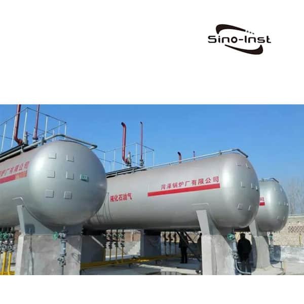
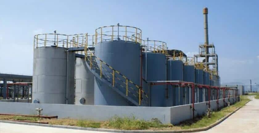
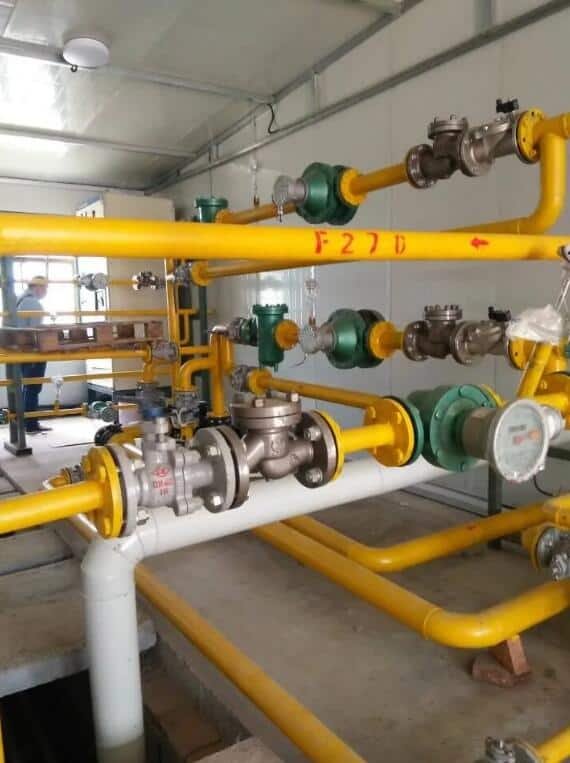
Chemical high-pressure pipeline, hydraulic oil, circulating oil, oil stations, construction machinery and other high-pressure occasion liquid.
The main disadvantage of high pressure turbine flow meters is that they are not suitable for applications where the fluid contains solids or particles, as these can damage the meter.
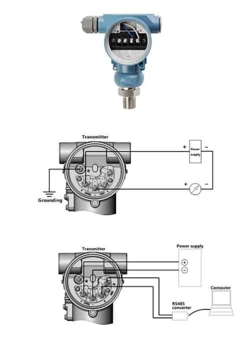
Extended reading: How To Install The Pressure Sensor When Measuring The Flow Pipeline?
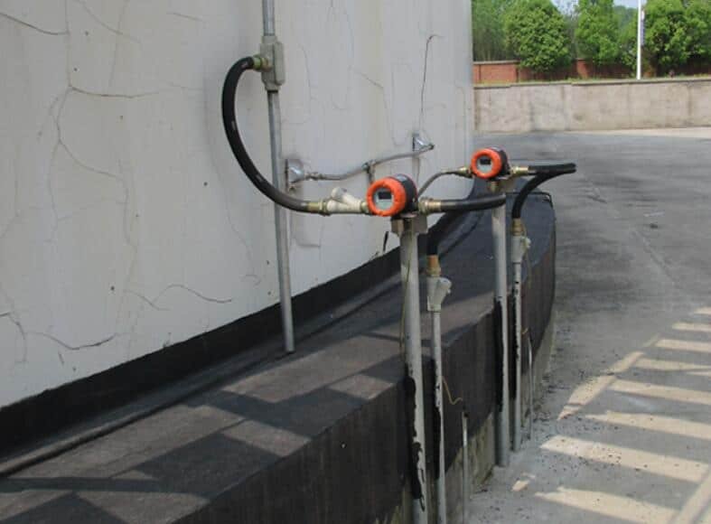
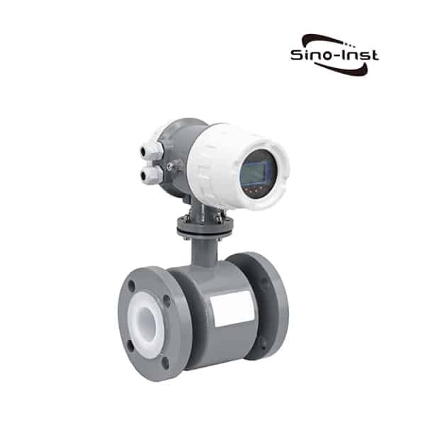
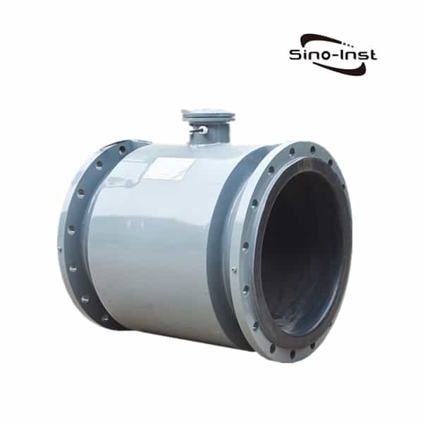
High-pressure electromagnetic flowmeter is used to measure the flow of conductive fluids in mining energy, steel, petroleum, chemical, electric power, industry, water conservancy, and other sectors. Can also measure acid, alkali, salt and other corrosive conductive liquids.

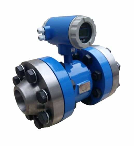
- Measurement medium: water, acid, alkali, seawater and other strong corrosion or impurities containing conductive liquids.
- Medium conductivity: ≥ 20uS/cm;
- Nominal diameter: DN6-DN3000mm;
- Lining material: polychloroprene, polytetrafluoroethylene, silicone fluorine rubber, polyurethane rubber, F46, PFA;
- Electrode material: key-containing stainless steel, Hastelloy B, Hastelloy C, titanium, aluminum, platinum-y alloy, tungsten carbide.
- Nominal pressure: 0.6MPa-42MPa;
- Precision grade: 0.2, 0.5, 1.0 grade.
- Flow rate range: 0.1m/s-15m/s;
- Ambient temperature: sensor -25℃~+60℃; converter -10℃~+60℃.
- Relative temperature: 5%-95%
Key Advantages:
Accurate and repeatable measurements;
No moving parts means low maintenance costs;
Can handle high pressures and high temperatures;
Key Disadvantages:
Requires a minimum conductivity of the fluid being measured;
Susceptible to interference from external magnetic fields;
Extended reading: Pressure Sensor Applications In Various Industries
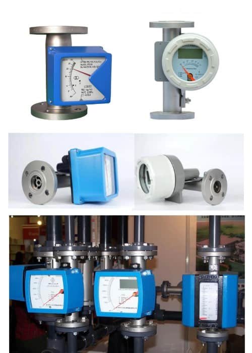
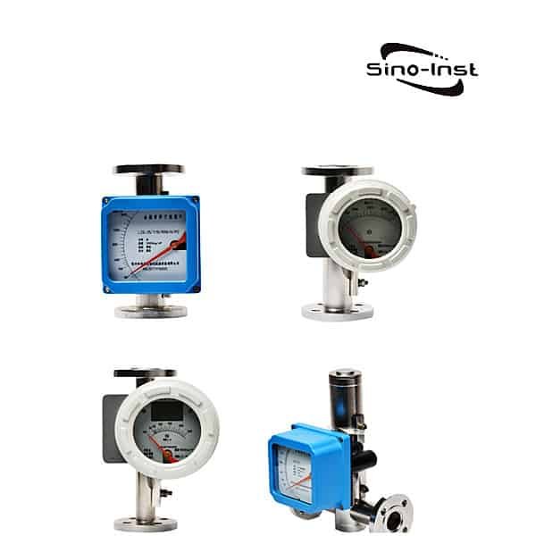
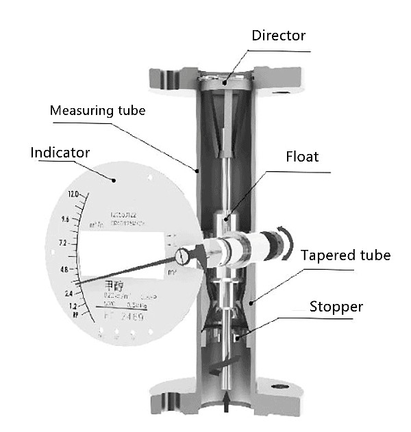
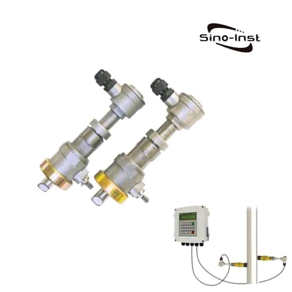
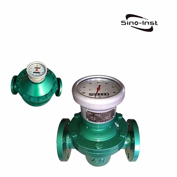
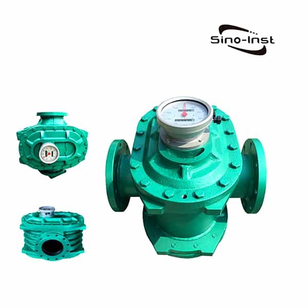
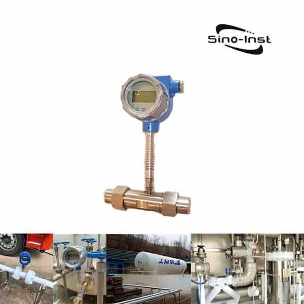
The gear flow meter is a type of volumetric flow meter.
It is made of stainless steel and can be customized with 40MPa high pressure.
The high pressure gear flow meter is especially suitable for low flow measurement.

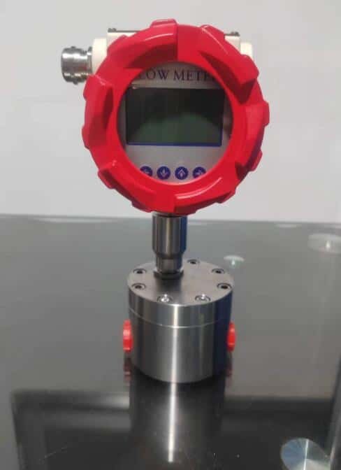
Features:
- High pressure resistance (1.0-40MPa)
- High and low temperature resistance (-196℃-200℃)
- Can measure various viscous media
- High precision and high repeatability
- Pulse output/analog output optional
- Wide range ratio (1:100)
- Wide measuring range
- High corrosion and stain resistance (acid and alkali)
Applications:
- Resin, glue measurement
- Ink, asphalt measurement
- Fuel oil measurement
- Hydraulic oil, lubricating oil, grease measurement
- Liquid nitrogen, freezing liquid, solvent measurement
- Edible oil, fish oil and food filling measurement
- Chemical and anti-corrosion requirement fluid measurement
- Fluid dosing control system
Extended Reading: Rotameter vs Flow meter

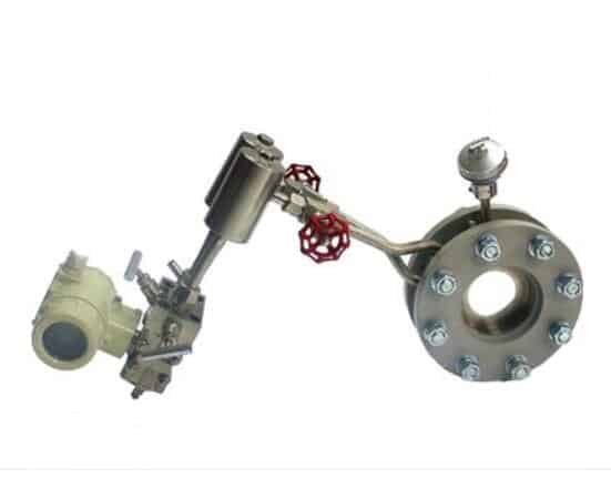
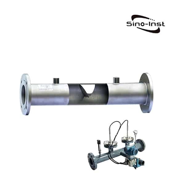
A high pressure orifice plate flowmeter is a device used to measure the flow of fluids through a pipe. It consists of a plate with an opening in the middle, through which the fluid flows. The plate is placed in the path of the fluid stream and the pressure drop across the plate is measured. This pressure drop is then used to calculate the flow rate. High pressure orifice plates are used in applications where the fluid being measured is under high pressure, such as in steam, oil and gas pipelines.
- Applicable measured media is very wide, can be used for almost all gases, steam and liquid flow measurement.
- Use pressure up to 32MPa, also can be used for negative pressure.
- Medium temperature range: -30°C to +650°C.
Extended Reading: Fluid pressure sensor
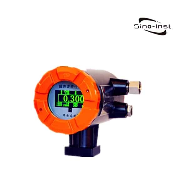
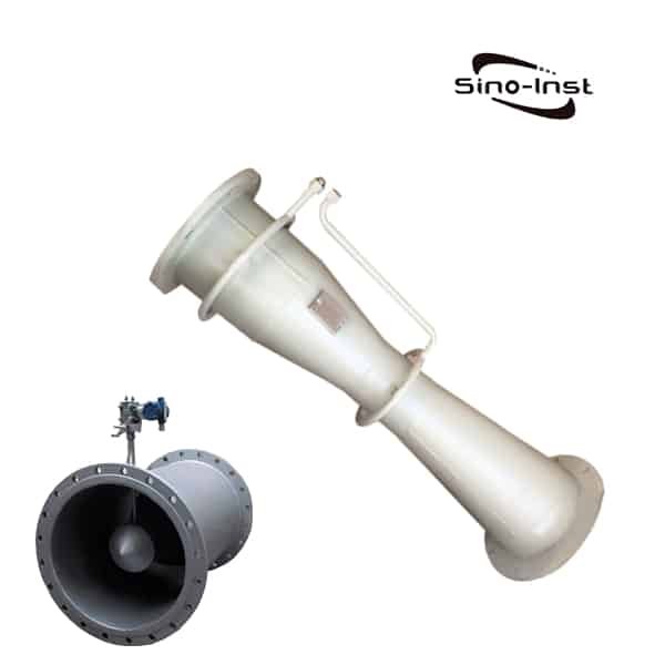
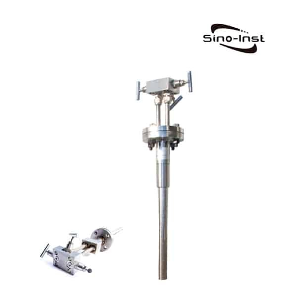
Bar type flowmeter will be inserted into the center of the pipe probe, the total pressure hole on the direction of the incoming fluid flow. Static pressure hole to the direction of the fluid to flow. The difference between the total pressure and static pressure is the measured differential pressure in the center of the pipe. Then the standard differential pressure at that point is fitted by the wind tunnel calibration curve of the probe.
It is mainly used in high temperature and high pressure high flow rate or ultra-high temperature and ultra-high pressure steam flow meter. It is made of high temperature resistant and impulse corrosion resistant 1Cr18Ni9Ti material.
The complete metal chamber structure is adopted to ensure the strength and steel. So that no damage to the mechanism will occur under the washout of high-speed airflow.
Matching temperature and pressure sensors are used to compensate for the temperature and pressure of the measured medium to ensure measurement accuracy.
- High temperature and pressure resistance: the primary element intelligent probe material selection 1Cr18Ni9Ti stainless steel ( according to different media selection of special steel ).
- Can withstand the maximum temperature of 650 ℃, the highest medium pressure 32MPa.

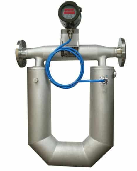
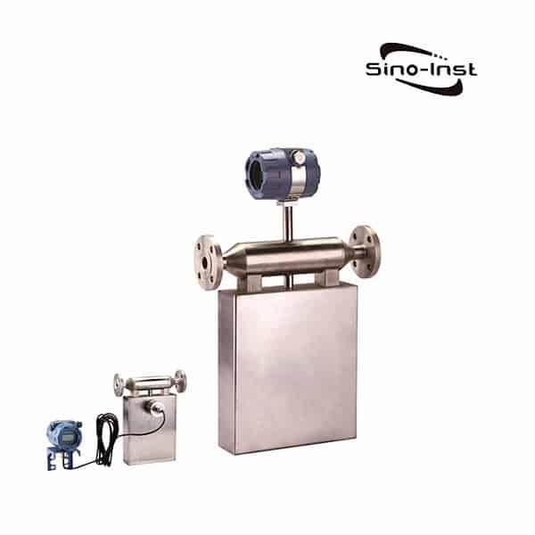
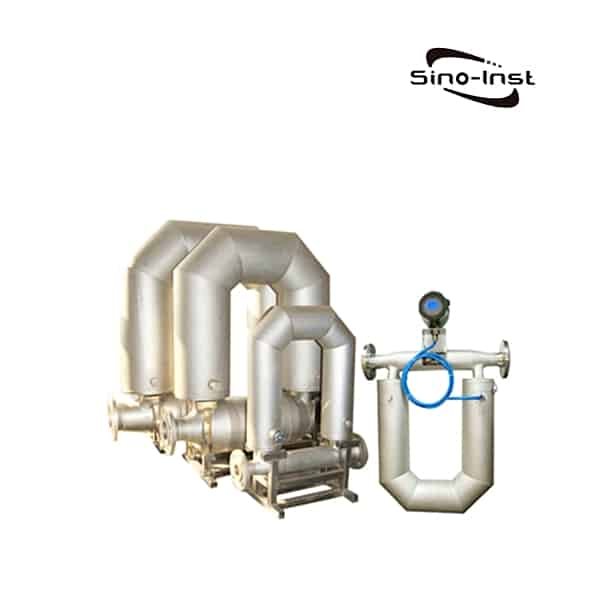
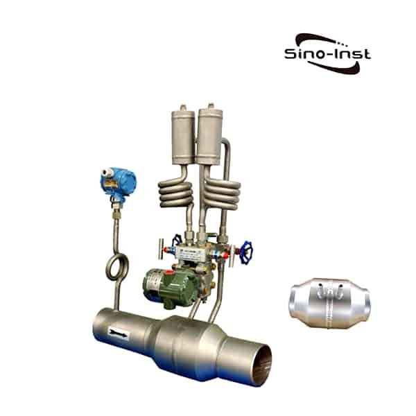
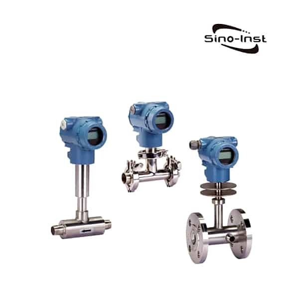
Mass flow meters are based on the Coriolis principle. The flow tube through which the medium flows vibrates, thus triggering the Coriolis effect. The sensor detects and analyzes the change in frequency, phase difference and amplitude of the flow tube. The mass flow rate and density of the fluid are calculated.
The high pressure coriolis mass flow meter is pressure resistant to 24 MPa. The type of process connection as well as the ambient and process medium temperature may reduce this rating.
Read more about: Condensate Flow Meter-Steam Condensate Flow Meter|Types & Selection Guide
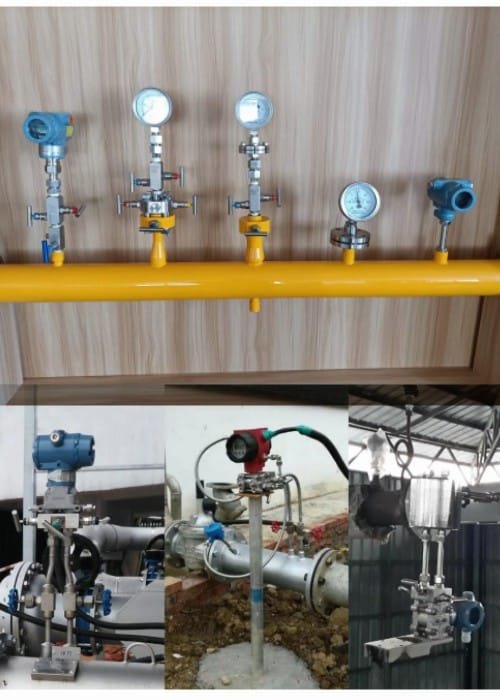
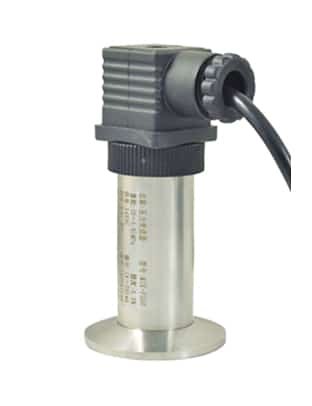
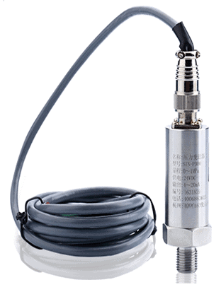
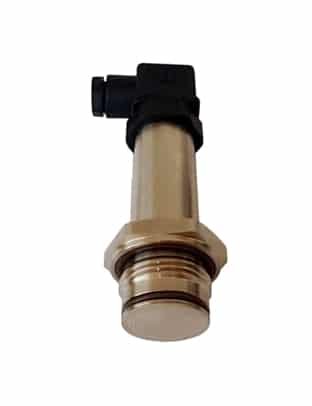
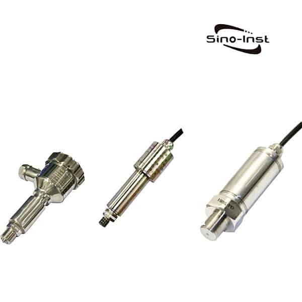
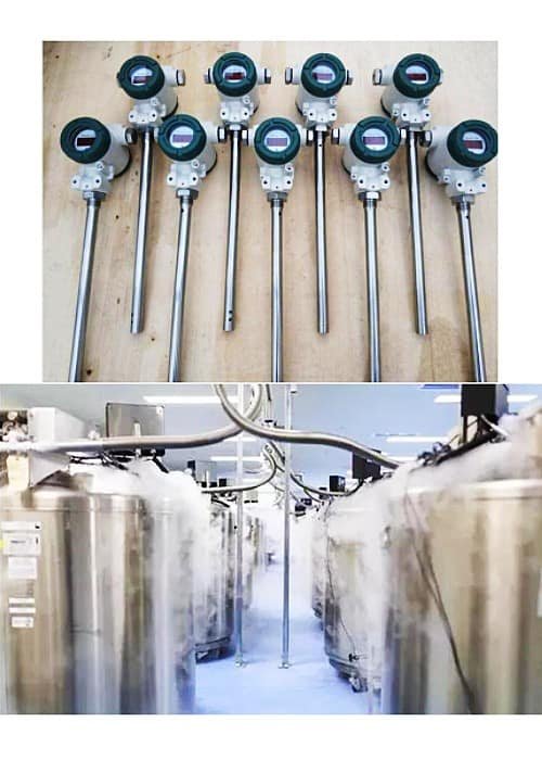
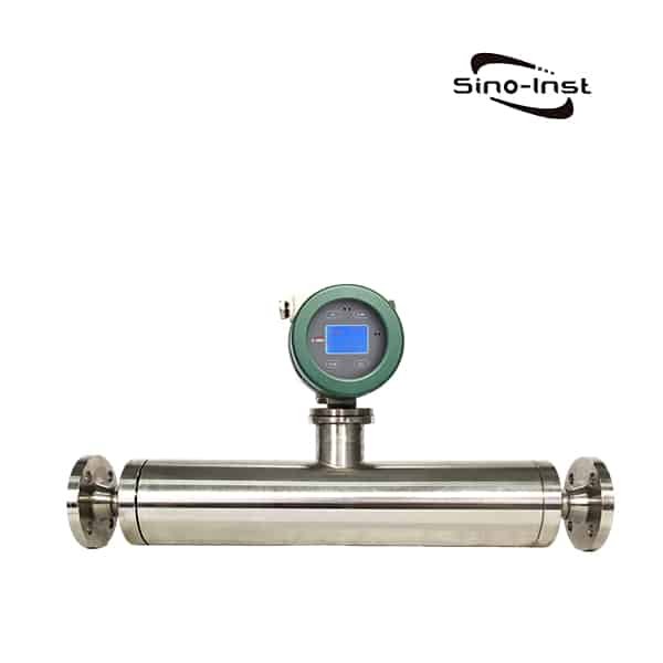
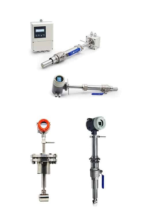
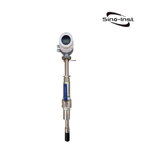
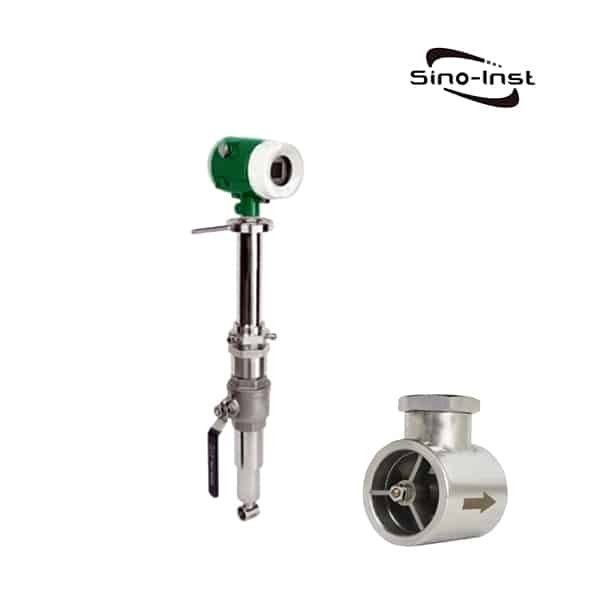
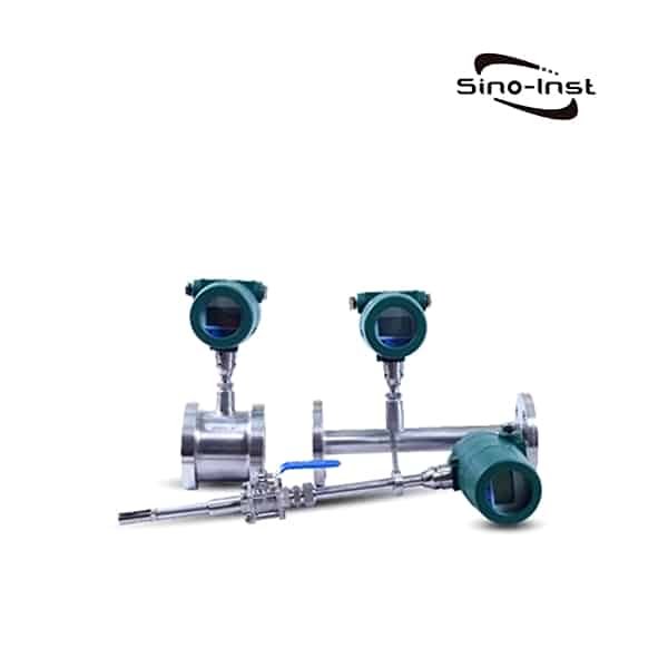
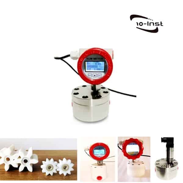
Featured High Pressure Flow Meters for Sale

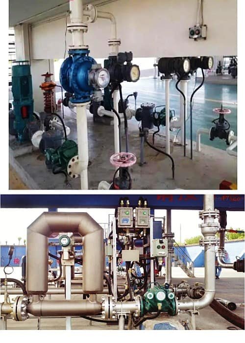
High pressure flow meters Applications
High pressure flow meters are recommended based on the application. High pressure gas, High pressure water, High pressure liquid, High pressure steam or High pressure air. High pressure oxygen is also a common application. Read more Turbine Flow Meter Application Case: Demineralized Water.
Some common applications for high pressure flow meters include:
- – High pressure gas flow measurement
- – High pressure water flow measurement
- – High pressure hydraulic flow measurement
- – High pressure steam flow measurement
- – High pressure air flow measurement
- – High pressure oxygen flow measurement
Read more about: High Pressure Hydraulic Flow Meter
When selecting a high pressure flow meter, it is important to consider the nature of the fluid being measured, the operating conditions and the required degree of accuracy. Each type of high pressure flow meter has its own advantages and disadvantages that should be considered in order to select the best meter for the application.
Read More about: What is the difference between rotameter and flowmeter?
More Related Flow Measurement Solutions
Extended Reading: Special Magnetic Flowmeter Installation situation
Sino-Inst is a manufacturer of High Pressure Flow Meters for Liquids-Steam-Gas. We offer more than 20 types of High Pressure Flow Meters, 40% for gas, 30% for liquid and the rest for steam. High Pressure Flow Meters include turbine, coriolis mass, and more DP flow meters.
High Pressure Flow Meter is mainly used for small and medium diameter flow measurement. It can measure liquid, gas, steam, etc. Complete product series specifications, in all walks of life are widely used.
High Pressure Flow Meters can be stable flow measurement without modifying the pipeline. This greatly meets the measurement needs of many applications. From small tubes to large tubes can be used.
Sino-Inst’s High Pressure Flow Meters, made in China, have good quality, with better prices. Our flow measuring instruments are widely used in China, India, Pakistan, USA and other countries.
Sino-Inst’s entire team is well trained, so we can ensure that each customer’s needs are met. If you need any help with your product requirements, whether it is a High Pressure Flow Meter, level sensors, or other equipment, please give us a call.
Request a Quote


Wu Peng, born in 1980, is a highly respected and accomplished male engineer with extensive experience in the field of automation. With over 20 years of industry experience, Wu has made significant contributions to both academia and engineering projects.
Throughout his career, Wu Peng has participated in numerous national and international engineering projects. Some of his most notable projects include the development of an intelligent control system for oil refineries, the design of a cutting-edge distributed control system for petrochemical plants, and the optimization of control algorithms for natural gas pipelines.