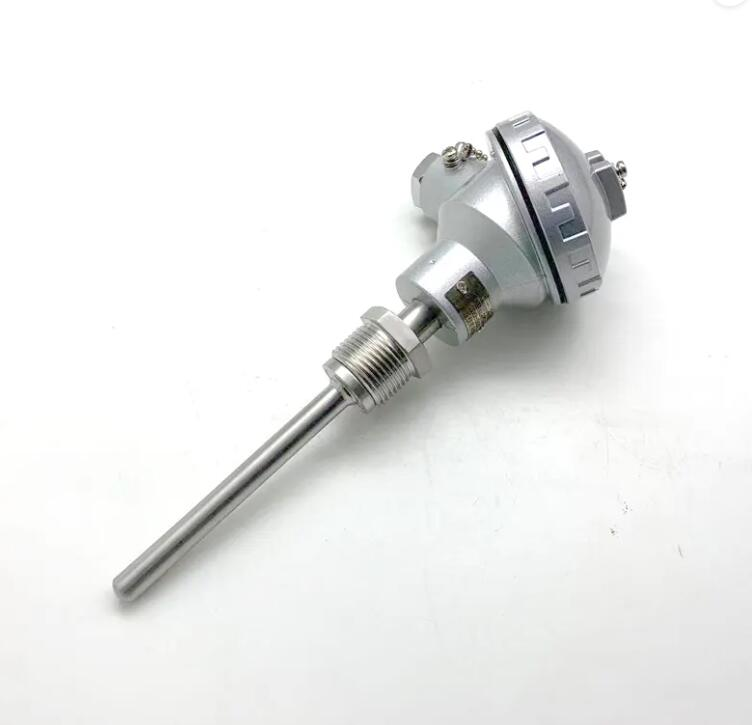
WZP PT100 is an industrial thermal resistance. It is used as a sensor for measuring temperature, and it is used in conjunction with display instruments, recording instruments and electronic regulators.
WZP PT100 industrial thermal resistance is the most commonly used temperature detector in the middle and low temperature areas. The main features are high measurement accuracy and stable performance. Among them, the measurement accuracy of platinum thermal resistance is the highest. It is not only widely used in industrial temperature measurement, but also made into a standard reference instrument.
Note: ︱ t ︱ is the absolute value of the humidity measured by the hygrometer;
More About WZP PT100
PT100 and RTD are both temperature sensors, but PT100 specifically refers to a type of RTD (Resistance Temperature Detector).
RTD is a type of temperature sensor that works by measuring changes in electrical resistance as temperature changes. PT100 RTDs have a resistance of 100 ohms at 0 degrees Celsius, which makes them a common choice for temperature measurement in industrial and scientific applications.
So, PT100 is just one type of RTD sensor that has a specific resistance value at a specific temperature.
A PT100 temperature sensor is a type of temperature sensor that measures temperature by detecting changes in electrical resistance. Specifically, it is an RTD (Resistance Temperature Detector) that has a resistance of 100 ohms at 0 degrees Celsius.
As the temperature changes, the resistance of the sensor also changes in a predictable way, allowing the sensor to accurately measure the temperature. PT100 sensors are commonly used in industrial and scientific applications where precise temperature measurement is important.
PTC and PT100 are both types of temperature sensors, but they work in different ways.
PTC stands for Positive Temperature Coefficient, and it is a type of thermistor that increases in resistance as temperature increases. In other words, the resistance of a PTC sensor goes up as the temperature it is measuring goes up. PTC sensors are commonly used in applications such as over-temperature protection in electronic circuits.
PT100, on the other hand, is a type of RTD (Resistance Temperature Detector) that has a specific resistance value of 100 ohms at 0 degrees Celsius. As temperature changes, the resistance of a PT100 sensor changes in a predictable way, allowing it to accurately measure temperature. PT100 sensors are commonly used in industrial and scientific applications where precise temperature measurement is important.
So, the main difference between PTC and PT100 is that PTC sensors increase in resistance as temperature increases. While PT100 sensors have a specific resistance value at a specific temperature and change resistance in a predictable way as temperature changes.
Calibrating a PT100 temperature sensor involves comparing its readings to known, accurate temperatures and making adjustments to the sensor’s output to ensure it is reading accurately.
Here are the basic steps for calibrating a PT100 sensor:
Obtain a reference thermometer or other temperature calibration device with a known, accurate temperature reading.
Place the reference thermometer and the PT100 sensor in a controlled environment with a stable temperature.
Wait for the temperature to stabilize and record the readings from both the reference thermometer and the PT100 sensor.
Compare the readings and calculate the difference between the two.
Adjust the output of the PT100 sensor as needed to match the reference thermometer reading.
Repeat the process at several different temperatures to ensure accuracy across a range of temperatures.
It’s important to note that calibrating a PT100 sensor can be a complex and technical process. And it may be best to consult with a professional or use specialized calibration equipment to ensure accurate results.
Here are some key differences between RTD temperature sensors and thermocouples:
RTD Temperature Sensors
Thermocouples
Higher accuracy and repeatability; Smaller temperature range; Less susceptible to EMI; More stable over time and exhibit less drift; Require a stable, regulated power source to operate; Can be more expensive;
Wider temperature range; Can operate in harsher environments; Do not require a power source to operate; Can be less expensive; More susceptible to EMI; Can exhibit more drift and require frequent calibration;
Standard Platinum Rhodium Thermocouple-Platinum Thermocouple Standard Platinum Rhodium Thermocouple is a temperature measurement standard device produced by our company. There…
A thermocouple chart is a practical tool for the electronic query of temperature index. It is used by technicians who…
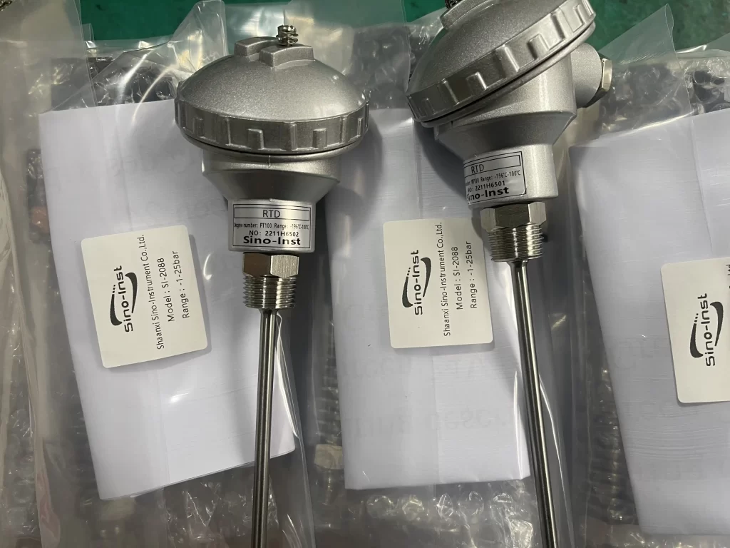
Industrial thermal resistance has the characteristics of high sensitivity and good stability and is widely used. If equipped with corrosion protection tube. Can also be used in corrosive media.
Wu Peng, born in 1980, is a highly respected and accomplished male engineer with extensive experience in the field of automation. With over 20 years of industry experience, Wu has made significant contributions to both academia and engineering projects.
Throughout his career, Wu Peng has participated in numerous national and international engineering projects. Some of his most notable projects include the development of an intelligent control system for oil refineries, the design of a cutting-edge distributed control system for petrochemical plants, and the optimization of control algorithms for natural gas pipelines.
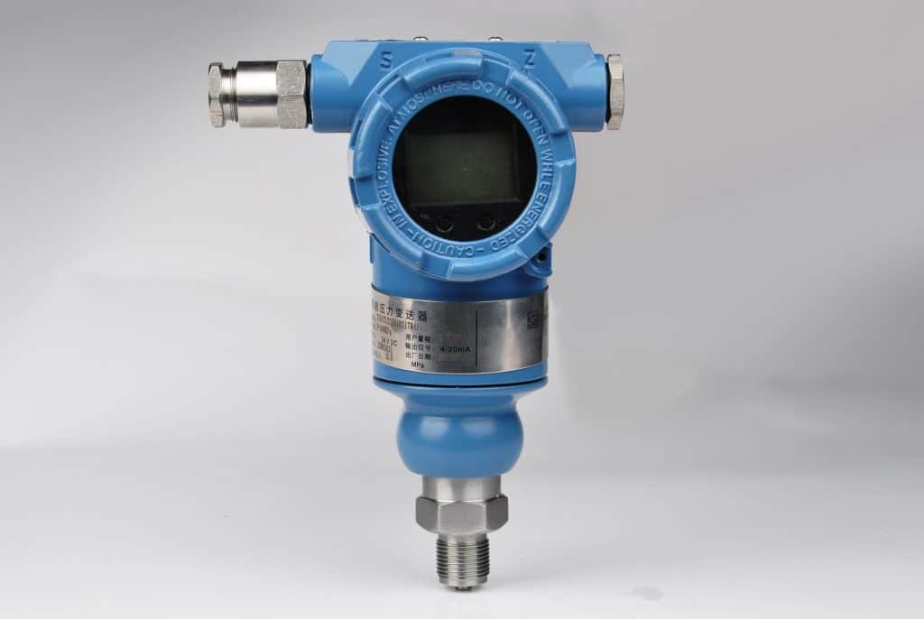
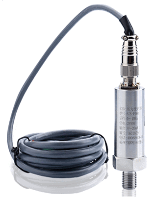
HART pressure transmitter is an SMART pressure measurement product. It is compatible with analog two-wire 4~20mA signals and HART protocol.
Users can use HART communicator to manage, adjust or monitor process variables of HART instruments running in the process. It can also be configured on site using buttons for easy operation.
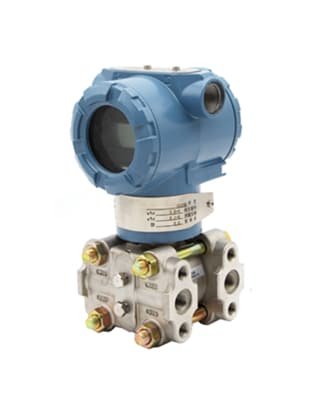
3051 HART Smart pressure transmitter that provides simplified field change, while communicating asset management data utilizing the latest HART 7 specification.
Sino-Inst offers a variety of HART pressure sensors for industrial pressure measurement. If you have any questions, please contact our sales engineers.
What is a communication protocol? A communication protocol refers to the specification for data exchange between different devices. In a pressure transmitter, a communication protocol is used to achieve data transmission between the transmitter and other devices.
HART is a digital communication protocol used for communication protocols between field intelligent instruments and control room equipment. The HART protocol can establish two-way communication between a 4-20mA sensor and a controller equipped with a two-way HART communication circuit.
Therefore, the pressure sensor can send a digital signal to the controller through the HART protocol. The controller can send commands to the sensor to set and adjust parameters.
The HART communication protocol of the pressure transmitter provides two synchronous communication channels: a 4-20mA analog signal and a digital signal. The 4-20mA signal uses a 4-20mA current loop to transmit the main measurement value.
The HART protocol allows digital information to be transmitted on a 4-20mA transmission loop. Therefore, without adding equipment, the coexistence of digital and analog signals can be achieved.
The HART protocol can simultaneously transmit analog signals and digital signals. Therefore, it is widely used in practical applications.
HART communication uses a digital signal superimposed on the analog signal of the pressure transmitter to transmit other device information of the pressure transmitter.
The digital signal of the pressure transmitter contains information from the device. Including device status, diagnostics, additional measurements or calculated values, etc.
The combination of these two communication channels of the pressure transmitter provides a low-cost, highly reliable, and complete field communication solution for pressure transmitters that is easy to use and configure.
Benefits of HART pressure transmitters
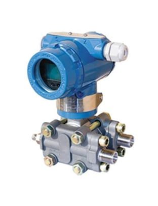
3151 HART pressure transmitter
4mA~20mA DC current output superimposed HART® protocol digital communication (two-wire system);
Adopt digital compensation and nonlinear correction technology;
-10℃~80℃ digital wide temperature compensation;
With local and remote zero and span adjustment functions;
Key operation on site for easy configuration;
Shorten troubleshooting time from discovery to problem solving;
Continuously verify the integrity of loops and control/automation system strategies;
Improve asset efficiency and system availability;
Quickly determine and verify control loops and device configurations;
Use remote diagnosis to reduce unnecessary on-site inspections.
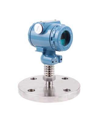
Featured Industrial HART Pressure Transmitters
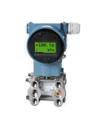
HART pressure transmitter is a complete product line of liquid level, differential pressure, gauge pressure and absolute pressure transmitter. Models include flushing diaphragms and sanitary flanges for liquid level measurement, hydrostatic tank metering – HTG. And wetted parts of various materials to suit the process requirements.
HART transmitters are much more complicated. The HART transmitter has the same pressure input and 4-20 mA output. But it also has an analog current loop output. The device contains some digital variables and settings. Access to these digital parameters requires the use of a HART configurator or communicator. This is essential for maintaining these devices. Just like Hart Communicator 375. In fact, many HART devices, cannot be maintained without access to digital parameters.
HART calibrator is our HART communicator for calibrating instruments. For example pressure transmitter, DP transmitter, liquid level transmitter, flowmeter, and temperature transmitter. HART communication protocol (Highway Addressable Remote Transducer) is a hybrid analog + digital industrial automation open protocol. Its most significant advantage is that it can communicate through the traditional 4–20 mA analog instrument current loop, sharing only a pair of wires used by the analog host system. We use this protocol in the HART calibrator.
HART communicator (such as HART 475) is the most common HART calibrator. The proprietary calibration process ensures optimal temperature compensation. This limits the thermal impact on the sensor output. It is suitable for the global process control industry. It provides a cost-effective solution for the use of conventional HART transmitters (such as the HART 475 field communicator).
HART protocol
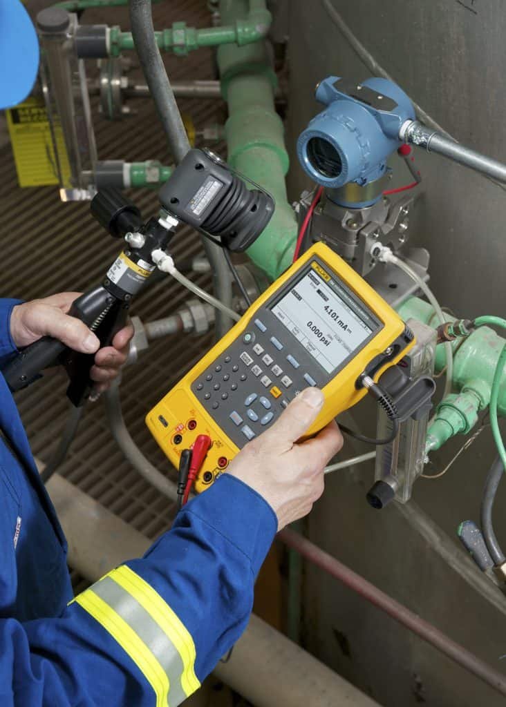
How to calibrate a pressure transmitter using Hart?
A pressure transmitter is one of the most common instruments in a process plant. To assure its accuracy, it needs to be calibrated.
But what do you need to calibrate it and how is it done?
You may knowhow to calibrate a pressure transmitter? Or, how to calibrate a differential pressure transmitter? Then, calibrate HART pressure transmitters, kind of like pressure transmitter calibration using a hart communicator. Pressure transmitter manufacturers have improved accuracy and technology, designed into these smart pressure measurement devices.
To calibrate a pressure transmitter, you need:
loop supply (if not connected to the controls system’s loop supply); a pressure generator to generate input pressure; an accurate calibrator to measure the input pressure; an accurate calibrator to measure the output mA current.
Typically, the pressure transmitter is a HART protocol transmitter. So in case, there is any need to adjust/trim it, you will need to use a device supporting HART communication.
How to calibrate HART pressure transmitters?
Explaining how to do the calibration would result in quite a long text. So we have put together a video for you instead. The video shows you how to calibrate and trim a HART pressure transmitter. Please have a look at the video: How to calibrate HART pressure transmitters
1. Isolate the transmitter from the process being measured and its loop wiring.
2. If measuring the mA signal across the transmitter test diode leave the wires intact, but note this method does not give the best mA measurement accuracy.
3. Connect the mA measurement jacks of the 754 to the transmitter.
4. Connect the pressure module cable to the 475, and connect the transmitter test hose from the hand pump to the transmitter. Press the HART button on the calibrator to see the configuration of the transmitter.
5. Press HART again and the calibrator will offer the correct measure/source combination for the test.
6. If documenting the calibration press As-Found, input the test tolerance and follow the prompts.
7. If the measured mA signal at the test points is found within tolerance the test is complete. If not, change is required. Select, adjust, and trim the pressure zero, mA output signal and input sensor.
If you still do not know, how to check the pressure transmitter? Or, how to calibrate a pressure transmitter.
Sino-Inst sells through a mature distribution network that reaches all 50 states and 30 countries worldwide. HART Pressure Transmitter products are most popular in Domestic Market, Southeast Asia, and Mid East. You can ensure product safety by selecting from certified suppliers, with ISO9001, ISO14001 certification.
Request a Quote
Please enable JavaScript in your browser to submit the form
Wu Peng, born in 1980, is a highly respected and accomplished male engineer with extensive experience in the field of automation. With over 20 years of industry experience, Wu has made significant contributions to both academia and engineering projects.
Throughout his career, Wu Peng has participated in numerous national and international engineering projects. Some of his most notable projects include the development of an intelligent control system for oil refineries, the design of a cutting-edge distributed control system for petrochemical plants, and the optimization of control algorithms for natural gas pipelines.
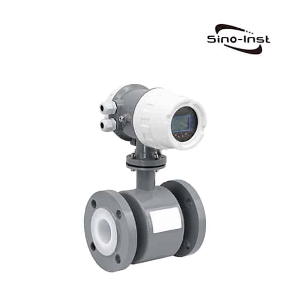
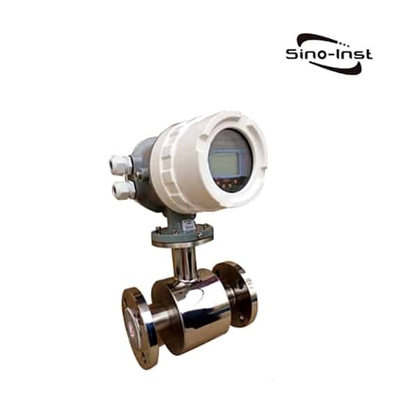
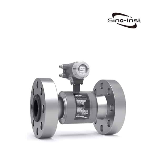
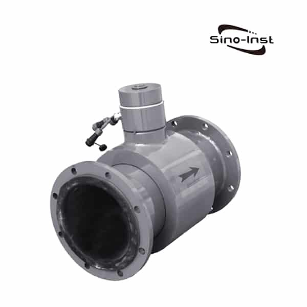
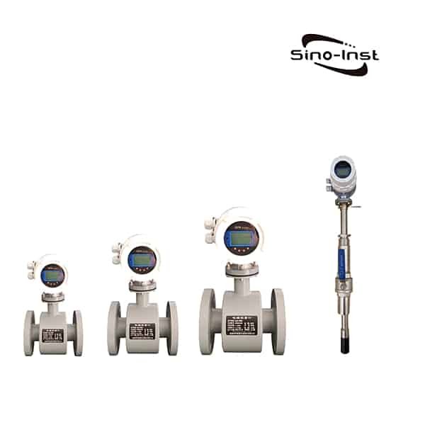
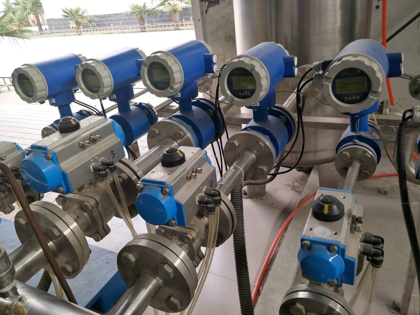
Magmeter Flow Meters are also called Electromagnetic flow meters or magnetic meters. Magmeter Flow Meter is a type of volumetric flow meter. It is mainly used to measure high-precision flow measurements of various conductive fluids. Such as water-based liquids, mixed media such as mud and sludge can also be measured.
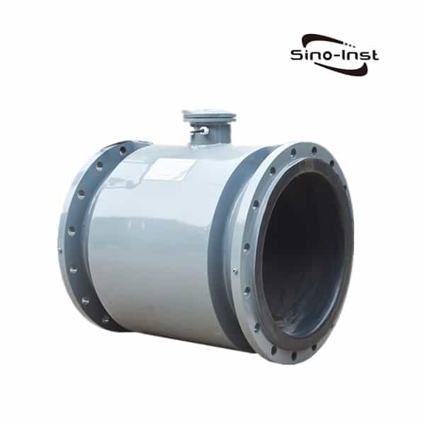
Magmeter Flow Meters are based on the principle of electromagnetic induction. We Sino-Inst offer a range of full-bore and insertion electromagnetic meters. Covering pipe diameters from DN6 to DN3000. Accuracy can reach 0.5%.
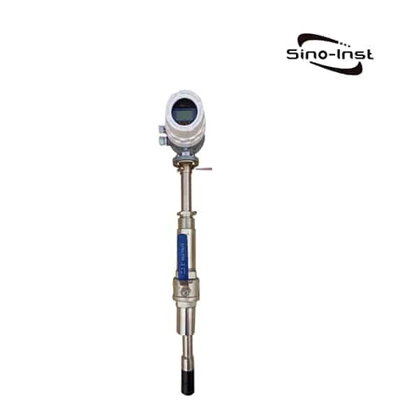
Suitable for measuring two-phase flow containing suspended matter, solid particles, fibers, etc. Such as mud, sewage, ore pulp, pulp, and other viscous slurries.
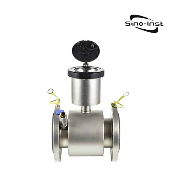
It uses four electrodes and a built-in grounding electrode. It is used for non-conductive pipes without the need for additional electrical rings.
It also has 420mA current signal output, pulse output, and instantaneous flow upper and lower limit alarm outputs. RS485 communication and HART protocol are also available.
On-site display of instantaneous flow, percentage, flow rate, forward and reverse cumulative flow, and total cumulative amount.
The power supply mode can be selected from AC85V~AC220V or DC24V.
Daily reports, monthly reports, annual reports, power failures, and other functions can be queried with one click.
More Flow Meters
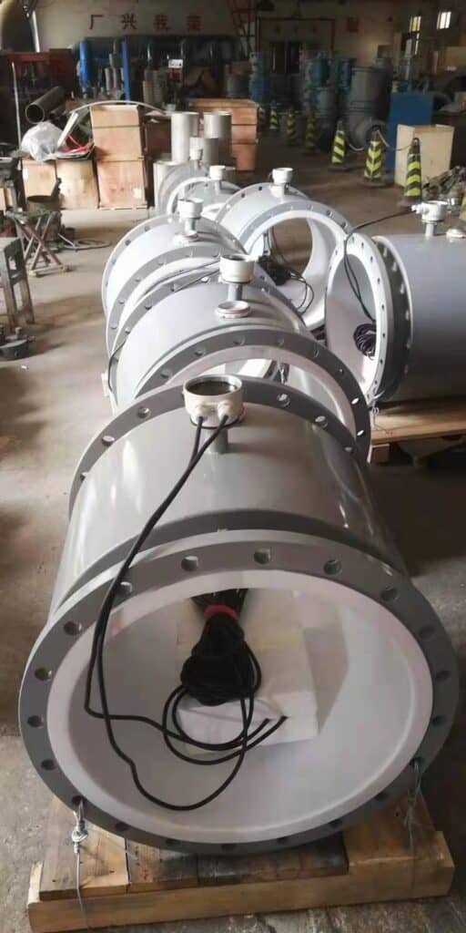
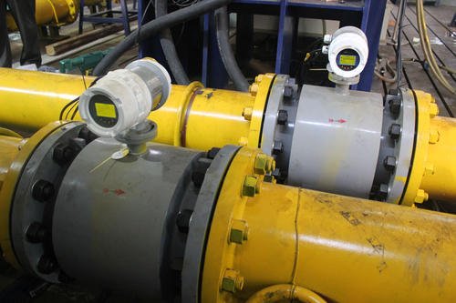
First, let us look at the structure of the magmeter.
The structure of electromagnetic flowmeter is mainly composed of magnetic circuit system, measuring catheter, electrode, shell, lining and converter.
The electromagnetic flowmeter is made according to Faraday’s law of electromagnetic induction. It is used to measure the volume flow of conductive liquid.
Faraday’s law of induction (referring to the induction of an electric potential inside the conductor when the conductor passes through a magnetic field) is the basic principle of electromagnetic flowmeter measurement.
This measurement principle can be applied to conductive fluids.
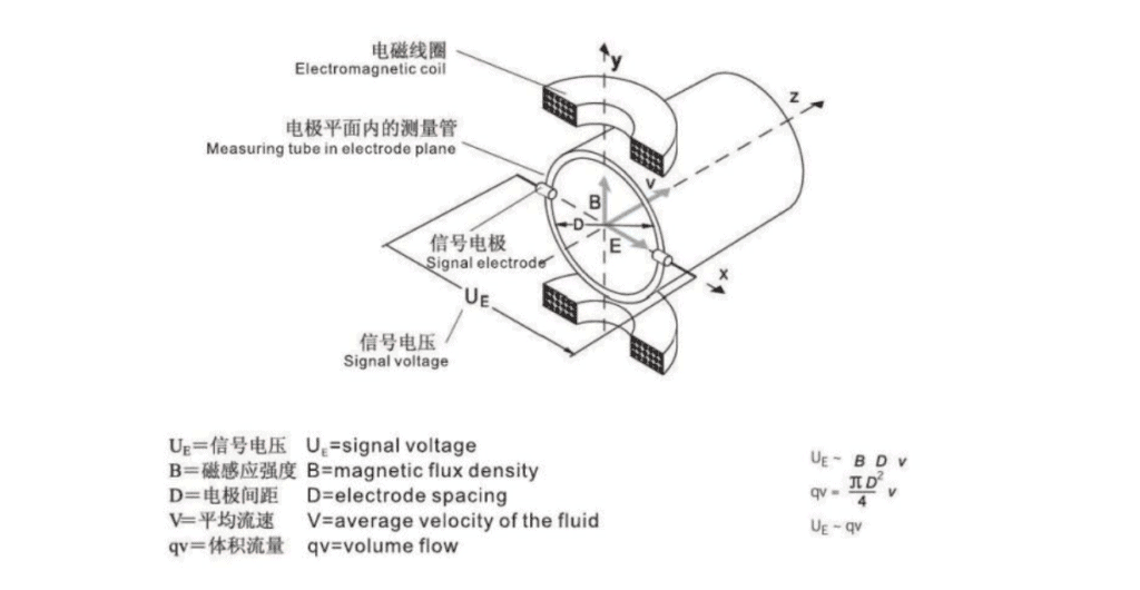
The fluid flows into a pipe whose magnetic field is perpendicular to the direction of the fluid, and the electric potential induced in the fluid can be measured using two symmetrically arranged electrodes.
The signal voltage UE is proportional to the magnetic induction intensity B, the electrode spacing D and the average fluid velocity v.
Because the magnetic induction intensity B and the electrode spacing D are constant. Therefore, the signal voltage UE is proportional to the average flow velocity v.
The equation used to calculate the volume flow rate shows that the signal voltage UE is linearly proportional to the volume flow rate.
The sensed signal voltage is converted into the graduation in the converter, analog and digital output signals.
Magmeter flowmeters measure the velocity of conductive liquids (such as water, acid, caustic and slurry) in the pipeline. When measuring deionized water, the minimum conductivity of the medium is 20uS/cm. For most liquids, the minimum conductivity required for measurement can be 5uS/cm.
Magmeter is mainly used in the following areas:
Measure clean water, sewage, domestic water, raw water;
Various acid, alkali, salt and other solutions;
Mud, mineral pulp, paper pulp, and food liquids, etc.;
It is widely used in metallurgy, papermaking, water treatment, chemical industry, light industry, textile, food and beverage, catering, agricultural irrigation, hydropower station, oil production, electric power and mining industries.
Magmeter liner selection should be selected according to the corrosiveness, abrasiveness and temperature of the measured medium.
Hard/soft rubber is resistant to general weak acid and alkali corrosion. Temperature resistance is 65℃. Soft rubber has abrasion resistance.
Polytetrafluoroethylene (PTFE) is almost resistant to strong acid and alkali corrosion except hot phosphoric acid. The temperature of the medium can reach 130℃. But it is not resistant to wear.
Polyurethane rubber has good wear resistance. But it is not resistant to acid and alkali corrosion. Temperature resistance is also poor. The medium temperature is less than 65°C.
Liner Materials
Functions
Applications
Hard rubber
1. It is resistant to hydrochloric acid, acetic acid, oxalic acid, ammonia, phosphoric acid and 50% sulfuric acid, sodium hydroxide, and potassium hydroxide at room temperature. 2. Avoid strong oxidants.
1, below 70℃ 2. General acid, alkali, and salt solutions.
Soft rubber
1. It has good elasticity and good wear resistance; 2. It is resistant to the corrosion of general low-concentration acids, alkalis, and salt media, and is not resistant to the corrosion of oxidizing media.
1. The material with the most stable chemical properties in plastics. It can withstand boiling hydrochloric acid, sulfuric acid, nitric acid and aqua regia, as well as strong alkalis and various organic solvents; 2. Poor abrasion resistance and adhesion.
1.-40℃~+130℃C(PTFE), -40℃~+160℃(PFA); 2. Strong corrosive media such as acid and alkali; 3. Sanitary media.
PO
1. It can withstand hydrochloric acid, acetic acid, oxalic acid, ammonia, phosphoric acid, sulfuric acid, sodium hydroxide, and potassium hydroxide at room temperature. 2. It can withstand concentrated alkali and various organic solvents.
1. Below 70℃; 2. General acid, alkali, and salt solutions; 3. General water, sewage, mud, mineral slurry.
Ceramics
Wear resistance, high temperature resistance, corrosion resistance
Below 200℃
1.Environmental conditions:
Magmeter flowmeter, especially the flowmeter with intelligent LCD screen. The installation position should avoid direct sunlight as much as possible. The ambient temperature should be between 5℃~55℃.
2.Avoid strong interference sources
Choose a place where there is no strong electromagnetic field radiation to install the flowmeter.
Avoid devices that can easily cause electromagnetic interference, such as motors, transformers, and frequency converters.
The measurement principle of the flowmeter is based on Faraday’s law of electromagnetic induction, the original The initial signal is very weak, less than millivolt.
If there is strong electromagnetic field radiation near the flowmeter, it will affect the accuracy of the measurement and even fail to work normally.
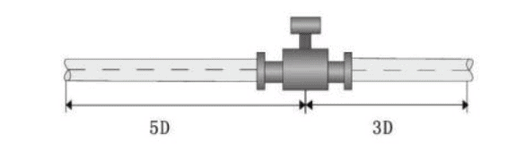
3.Magmeter straight run
Pay attention to avoid eddy current generating parts as much as possible. Such as various valves, elbows, bypasses, etc.
Try to extend the straight pipe section upstream and downstream of the flowmeter. Install a rectifier tube if necessary.
Ensure that the upstream straight pipe section of the flowmeter must be at least 5 DN (measurement pipe diameter). The downstream is guaranteed to be more than 2 DN.
4.The conductivity of the liquid must be uniform and stable
Do not install the flowmeter in a place where the conductivity of the fluid to be measured is extremely uneven. If different media are injected upstream, the conductivity will be uneven and will affect the measurement.
In this case, it is recommended to move the injection port downstream.
If it must be injected from upstream, it should be as far away from the flowmeter as possible. Generally, it is better to keep a distance of more than 20 DN. To ensure that the liquid is fully mixed and uniform.
5.Keep the electrode axis level
The plane of the intermittent measuring electrode must be kept level. This prevents short-term insulation between the two electrodes due to air bubbles.
6.Magmeter grounding rings
Since the induction signal of the electromagnetic flowmeter is very weak, it is susceptible to noise. Therefore, the reference potential of the sensor and the converter must be the same as the measured liquid, and be grounded together.
The purpose of installing grounding rings or grounding electrodes on both sides of the electromagnetic flowmeter is to establish the equipotentiality between the flowmeter casing and the liquid.
Ordinary metal pipe (generally no need to install grounding ring)
When the pipeline itself is well grounded, the grounding wire can be omitted, but the casing must be connected to the liquid through the grounding wire equipped with the flowmeter.
A grounding ring (or grounding electrode) should be installed at both ends of the sensor and the measured medium should be short-circuited with the earth through the grounding wire.
Cathodic protection pipeline
The pipe flanges are connected by copper wires, but they must be insulated from the grounding wire.
Magnetic flowmeter is a widely used flow measuring instrument. How should we calibrate it?
Let’s take a look at the calibration method of electromagnetic flowmeter:
Determine the corresponding water pump according to the pipe diameter and flow rate of the verification test;
After the flowmeter is correctly installed and connected, it should be energized and preheated for about 30 minutes in accordance with the requirements of the verification regulations;
If the high-level tank water source is used, check whether the overflow signal of the stabilized water tower appears. Before the formal test, use the verification medium to circulate in the pipeline system for a certain period of time. At the same time, check whether there is any leakage in the sealing parts of the pipeline;
The verification medium should be filled with the electromagnetic flowmeter sensor before the formal verification. Then the downstream valve should be closed to adjust the zero position;
At the beginning of the verification, open the valve at the front of the pipeline and slowly open the valve behind the electromagnetic flowmeter to adjust the flow at the verification point.
During the calibration process, the flow stability of each flow point should be within 1% to 2%-flow method. The total amount law can be within 5%.
The temperature change of the verification medium should not exceed 1℃ when the verification process of a flow point is completed. It should not exceed 5℃ when the entire verification process is completed.
There must be a sufficiently high pressure downstream of the electromagnetic flowmeter to be checked to ensure that no flashing and cavitation occur in the flow pipeline;
After the test, close the valve at the front end of the test pipeline. Then stop the pump to avoid emptying the voltage stabilization facility. At the same time, the remaining verification medium in the test pipeline must be vented and the control system and the air compressor must be closed.
A Rotameter flow meter is a variable area flow meter based on float position measurement. It is suitable for liquid and gas volumetric flow measurement and control.
All electromagnetic flowmeters need to be calibrated when they leave the factory. Each finished product needs to pass the calibration line inspection before leaving the factory.
It is to install the product on the assembly line. The front end adopts a strictly debugged standard table. A series of coefficients such as the diameter of the flowmeter, the damping coefficient, and the sensor coefficient of the electromagnetic flowmeter are set at the back end. To achieve the same flow rate as the standard meter.
If calibration is done on-site, it may generally be used to calibrate outside the sealed pipeline. Such as portable ultrasonic flowmeter. But the accuracy is generally 0.5. If you just check it, you can use a portable ultrasonic flowmeter.
Ultrasonic flow meters and electromagnetic flow meters have different measurement principles.
Electromagnetic flowmeter must measure conductive liquid. The ultrasonic flowmeter can measure pure single-phase liquid. It has nothing to do with the conductivity of the liquid.
The electromagnetic flowmeter must be in contact with the medium to measure. The ultrasonic flowmeter can do contact and non-contact measurement.
The electromagnetic flowmeter is a flow measuring instrument. The measuring principle of the electromagnetic flowmeter is measured according to its principle of conduction. Most of the flow measurement on the market is solved by electromagnetic flowmeters.
The electromagnetic flowmeter is a pure liquid volume measurement instrument.
The mass flow meter is a function of fluid volume and fluid temperature and pressure. Is a dependent variable. The quality of a fluid is a quantity that does not change with time, space temperature, and pressure.
Mass flow meters are compared with electromagnetic flow meters. It can measure non-conductive media. This is one of the biggest differences. In addition, the accuracy of the mass flow meter is higher. The cost is large, and there are fewer applications in the market.
There is a big difference in the performance of general-purpose electromagnetic flowmeters on the market. Some have high precision and many functions. Some have low precision and simple functions.
The basic error of the instrument with high accuracy is (±0.5%~±1%)R. The instrument with low accuracy is (±1.5%~±2.5%)FS. The price difference between the two is 1 to 2 times.
Petrol flow meters are often used for inline monitoring of gasoline flow rates. Positive displacement & Turbine flow meters are commonly used industrial fuel flow…
CO2 flow meters are instruments that can measure the flow of gaseous or liquid carbon dioxide. CO2 is a common industrial gas, and effective measurement…
LPG flow meter is used for flow measurement of liquefied petroleum gas. The flow measurement of LPG is very important in industrial production, transportation and…
Featured Inline Propane Flow Meter Propane is also generally referred to as liquefied petroleum gas (LPG). So what is the difference and connection between propane…
Clamp on flow meters refers to the non-contact flow meter, or strap-on flow meters, which clamps the ultrasonic sensor outside the pipeline for measurement. Sino-Inst…
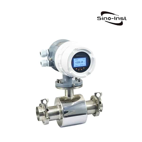
Common sanitary flow meters are sanitary magnetic flow meters and sanitary turbine flow meters. Composed of 304/316 stainless steel. A Sanitary flowmeter with Tri-Clamp fittings…
Cryogenic Flow Meters for Highly Accurate and Reliable Cryogenic Fluids Flow Measurement. Sino-Inst offers a variety of Cryogenic Flow Meters for Cryogenic fluids flow measurement…
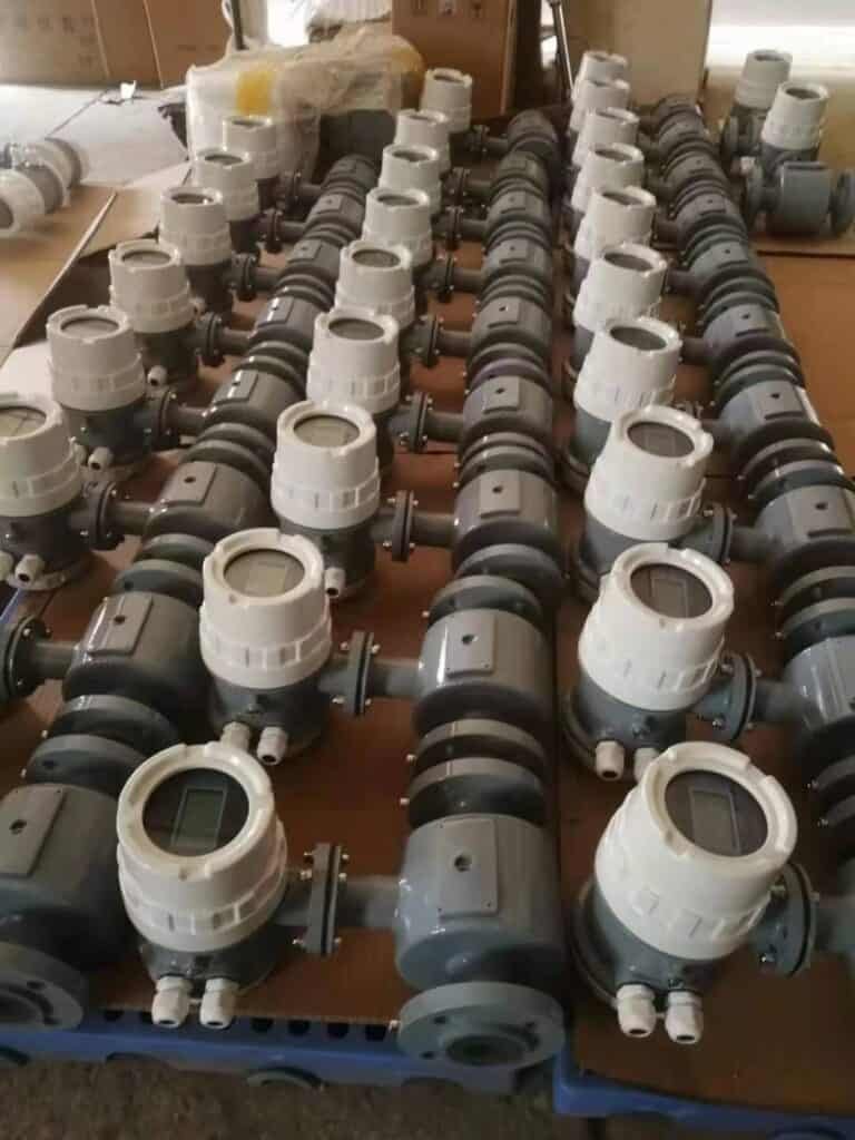
Magnetic flow meter manufacturers
Sino-Inst is one of the reliable Magnetic flow meter manufacturers and suppliers in China. Magnetic flow meters are applied for wastewater flow rate measurement.
Sino-Inst offer over 20 Magnetic flow meters, at the Best Price. A wide variety of Magmeters options are available to you, such as free samples, and paid samples.
Wu Peng, born in 1980, is a highly respected and accomplished male engineer with extensive experience in the field of automation. With over 20 years of industry experience, Wu has made significant contributions to both academia and engineering projects.
Throughout his career, Wu Peng has participated in numerous national and international engineering projects. Some of his most notable projects include the development of an intelligent control system for oil refineries, the design of a cutting-edge distributed control system for petrochemical plants, and the optimization of control algorithms for natural gas pipelines.
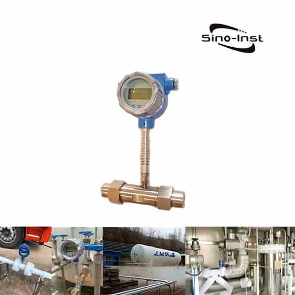
Sino-Inst is a Turbine Flow Meter Manufacturer from China. Our turbine flow meters are widely used to measure liquid and gas flow in a variety of industrial, commercial and laboratory applications.
Sino-Inst offers turbine flowmeters for liquids, gases, and more. We can provide you with precision flow measurement solutions at the best price.
Sino-Inst is a leading manufacturer of turbine flowmeters, providing a variety of instruments used in many industries. Including water treatment, food and beverage production, and pharmaceutical research.
We offer a range of products suitable for almost all applications. These include:
Water turbine flowmeter;
Diesel turbine flowmeter;
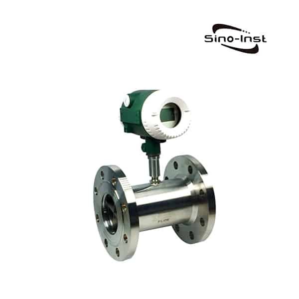
304 SS and 316 SS turbine flowmeters with pulse or 4-20mA output;
Plastic material turbine flowmeter;
Low flow brass and 316 SS turbine flowmeter
Ultra-high pressure turbine flowmeter;
High temperature, extremely low temperature turbine flowmeter;
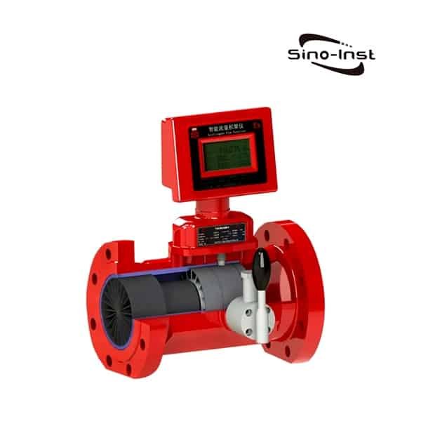
Gas turbine flowmeter, etc.
When you need reliable, accurate, and best-priced turbine flowmeters, Sino-Inst is your one-stop shop.
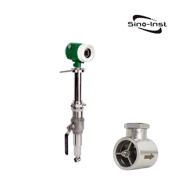
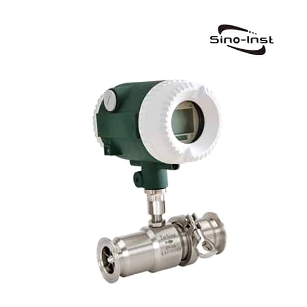
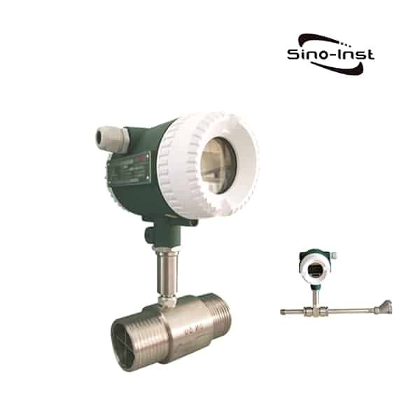
A turbine flow meter is a type of flow meter that works by measuring the velocity of a fluid or gas as it passes through a turbine rotor. Turbine flow meters are commonly used to measure the flow of liquids and gases in a wide range of applications. They offer a high level of accuracy, especially in high flow rate applications, and can be used for both clean and dirty fluids. Turbine flow meters are also relatively easy to install and maintain, making them a popular choice in many industries.
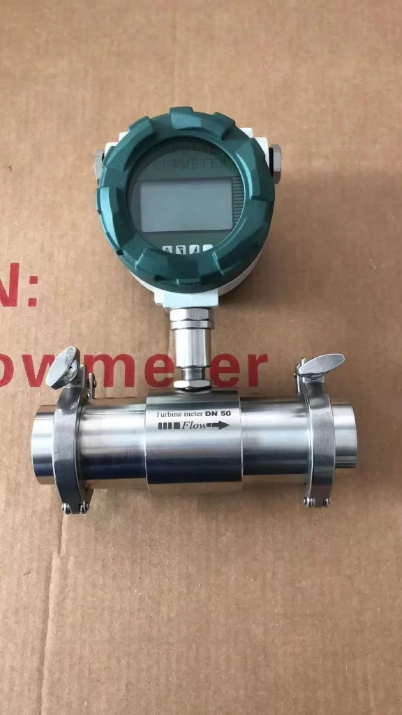
Turbine flowmeter is composed of turbine, bearing, preamplifier and display instrument.
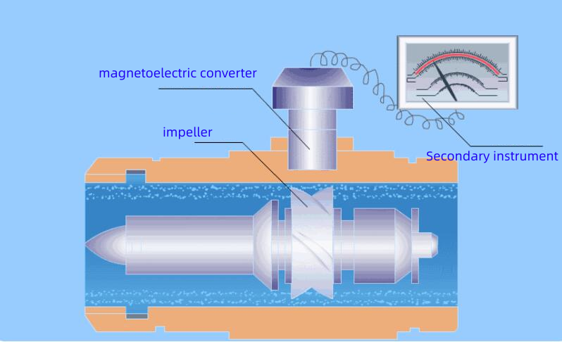
The principle of the turbine flowmeter is to place a turbine in the center of the pipeline, and the two ends are supported by bearings. As the fluid passes through the pipes, it strikes the turbine blades. Drive torque to the turbine. Make the turbine rotate by overcoming the friction torque and fluid resistance torque.
In a certain flow range, for a certain fluid medium viscosity, the rotational angular velocity of the turbine is proportional to the fluid velocity. Thus, the fluid flow rate can be obtained from the rotational angular velocity of the turbine, so that the fluid flow through the pipeline can be calculated.
The fluid to be measured impacts the turbine blades, causing the turbine to rotate, and the rotation speed of the turbine changes with the change of the flow rate. That is, the flow rate is large, and the speed of the turbine is also large. Then the rotation speed of the turbine is converted into electric pulses of corresponding frequency by the magnetoelectric conversion device. After being amplified by the preamplifier, it is sent to the display instrument for counting and display. According to the pulse number and cumulative pulse number per unit time, the instantaneous flow and cumulative flow can be calculated.
Turbine flow meters offer a number of advantages over other types of flow meters. Here are some of the key benefits of using turbine flow meters:
High accuracy: Turbine flow meters offer a high level of accuracy, especially in high flow rate applications. They have an accuracy of ±0.5% to ±1.0% of reading.
Wide flow range: Turbine flow meters have a wide flow range capability. They can measure flow rates from as low as 0.1 GPM (gallons per minute) to as high as 10,000 GPM, depending on the model and size.
Quick response time: Turbine flow meters have a fast dynamic response time, which means that they can measure changes in flow rate quickly.
Versatile: Turbine flow meters can be used to measure the flow of a wide range of fluids and gases. Including hydrocarbons, chemicals, water, cryogenic liquids, air, natural gas, and industrial gases.
Overall, turbine flow meters are a reliable and cost-effective method for achieving high accuracy flow measurement.
No, a rotary meter is a different type of flow meter than a turbine meter. While both are used to measure the flow of liquids or gases, they operate on different principles and have distinct designs.
A rotary meter, also known as a positive displacement meter, works by dividing the fluid or gas being measured into specific volumes and then counting the number of volumes that pass through the meter.
In contrast, a turbine flow meter works by measuring the velocity of the fluid or gas as it passes through a turbine rotor. The rotor spins at a speed proportional to the flow rate, and this motion generates an electrical signal that can be used to measure the flow rate.
While both types of flow meters are used for measuring the flow of liquids or gases, they are different in their operation and design.
As a Turbine Flow Meter Manufacturer- We Can Offer
Extensive customization services:
Product brand OEM
Product parameters customization:
Temperature, high temperature or low temperature liquid (liquid nitrogen, liquid oxygen, etc.);
Pressure, especially high pressure products, 16MPa, 25MPa, 32MPa, etc.;
Connecting flange: Accept flange thread customization such as German standard DIN, American standard ANSI, and Japanese standard JIS.
Last but not least. We can offer you the most reasonable price. The cheapest price is not necessarily the best product. Reference: DN50 Turbine Flow Meter Price, FOB Price USD 298.00/set.
Sino-Inst is one of the reliable turbine flow meter manufacturers and suppliers in China. Of course, there are also many Leading Turbine Flow Meter Manufacturers in the international market. For example:
The turbine flow meters we supply from Sino-Inst include liquid turbine flow meters, gas turbine flow meters, etc. We can provide you with precision flow measurement solutions at the best price.
Sino-Inst’s turbine flow meters are made in China. Good quality and more favorable prices. Our flow measurement instruments are widely used in the United States, Indonesia, Singapore, and other countries.
Request a Quote
Please enable JavaScript in your browser to submit the form
Wu Peng, born in 1980, is a highly respected and accomplished male engineer with extensive experience in the field of automation. With over 20 years of industry experience, Wu has made significant contributions to both academia and engineering projects.
Throughout his career, Wu Peng has participated in numerous national and international engineering projects. Some of his most notable projects include the development of an intelligent control system for oil refineries, the design of a cutting-edge distributed control system for petrochemical plants, and the optimization of control algorithms for natural gas pipelines.