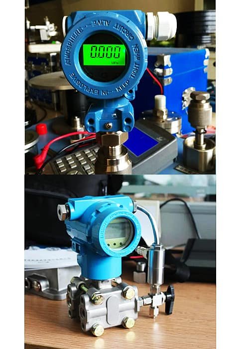
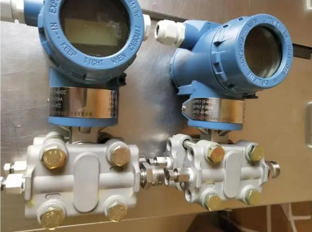
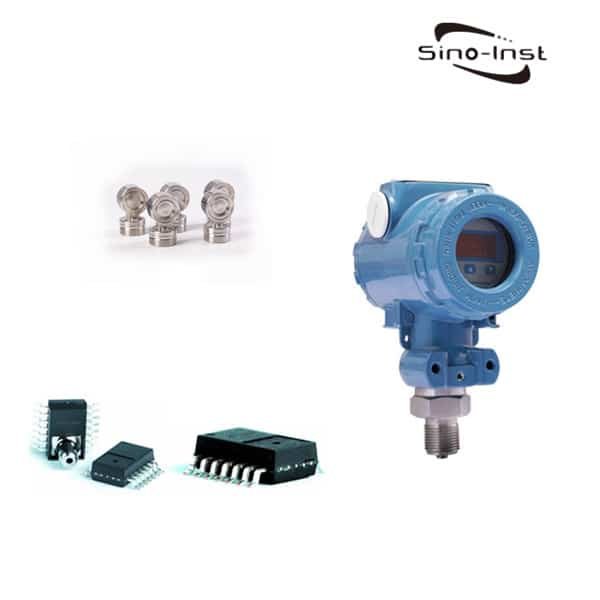
What is a pressure transmitter?
A pressure transmitter also often called a pressure transducer. A pressure transmitter is a device used to measure the pressure of liquids or gases in pipes or containers. It works by converting the pressure readings into an electrical signal that can be easily transmitted to a control system for monitoring and analysis.
These devices are commonly used in industrial settings, such as in manufacturing plants and refineries. Where it’s important to monitor the pressure of gases and liquids flowing through pipes and containers to ensure that they’re at safe levels.
Pressure transmitters can measure pressure in gases, liquids, air or oil. Widely used in various industrial processes. Such as pharmaceutical industry, chemical feed, waste water industry, food industry, farms, etc.
Overall, pressure transmitters are essential tools for measuring and monitoring pressure levels in various settings, helping to keep people and equipment safe and functioning properly.
In order to choose a suitable pressure transmitter, we must understand what types of pressure transmitters are there, what are the functions of pressure transmitters, and how do pressure transmitters work? Read on to find out the answers below.
Types of Pressure Transmitters
According to different measurement media, pressure transmitters can be divided into liquid pressure transmitters and gas pressure transmitters.
According to the measurement conditions, the pressure transmitter can have a high temperature type, a very low temperature type, and a high pressure type.
Here we divide by the type of pressure measured.
| Type of Pressure Transmitter | Characteristics/Principles |
| Absolute Pressure Transmitter | – Measures pressure relative to atmospheric pressure – Can only measure positive pressures |
| Gauge Pressure Transmitter | – Measures pressure relative to atmospheric pressure – Can only measure positive pressures |
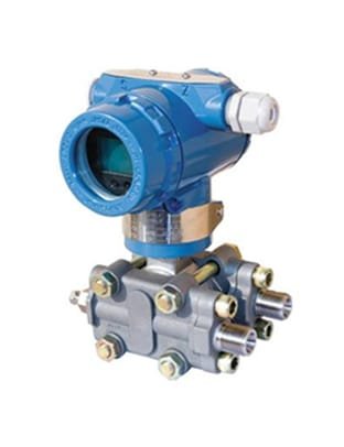
| Differential Pressure Transmitter | – Measures the difference between two pressures – Can measure both positive and negative pressures<br>- Used to measure flow rates |
| Vacuum Pressure Transmitter | – Measures pressure below atmospheric pressure – Can only measure negative pressures – Used to maintain vacuum in a process |
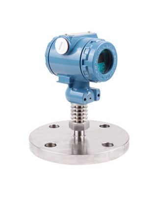
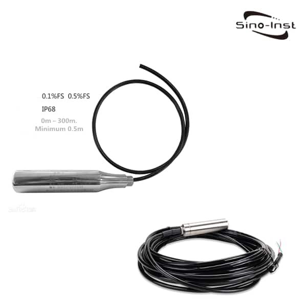
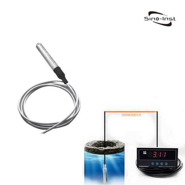
| Hydrostatic pressure transmitters | – Often called level transmitters. Because of their working principle and ability to measure level. – Hydrostatic pressure transmitters work on the basis that the amount of pressure increases with depth. – These devices are submersible and can be used for liquids and gases. |
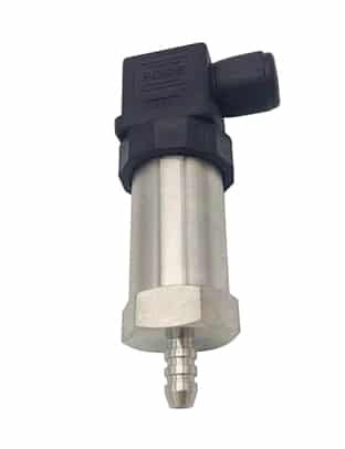
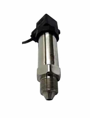
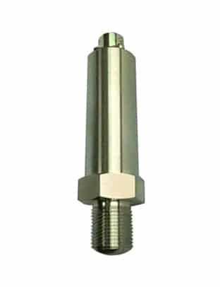
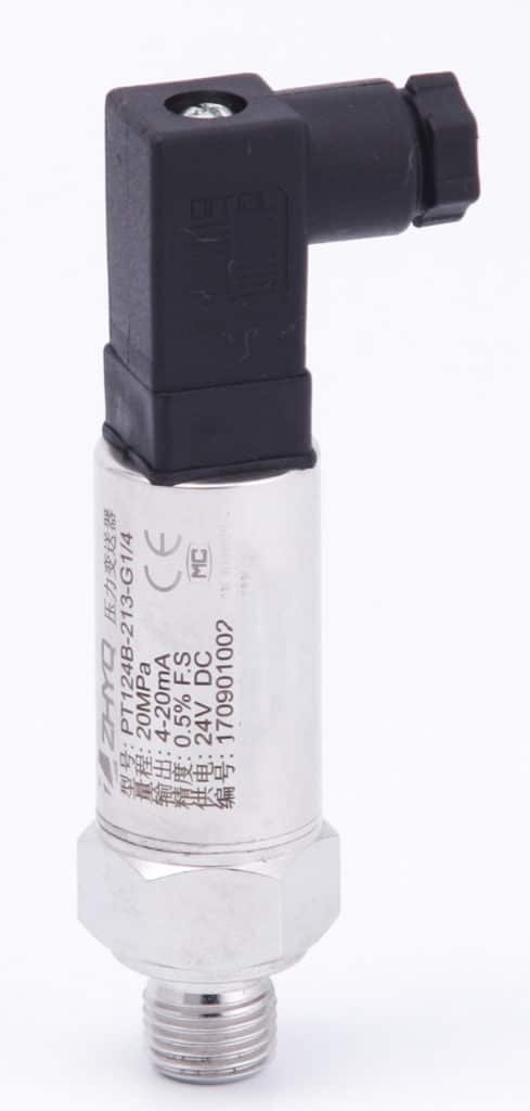
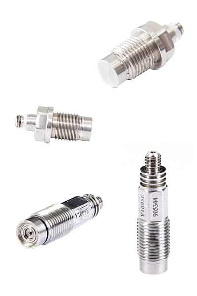
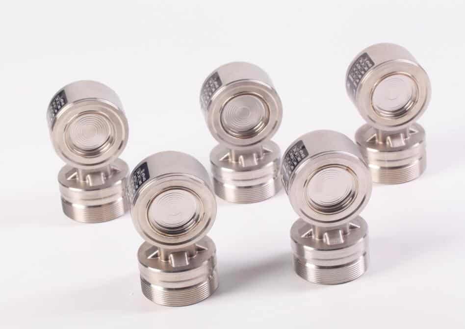
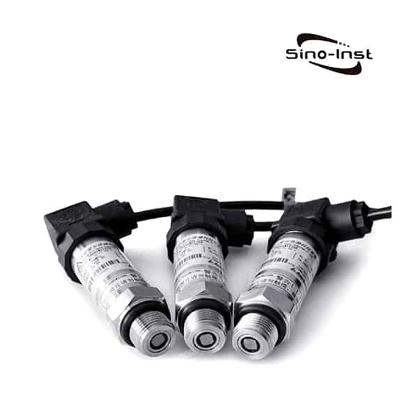
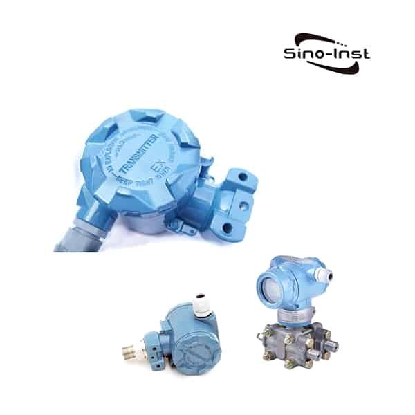
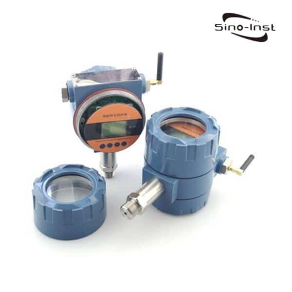
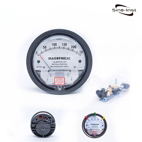
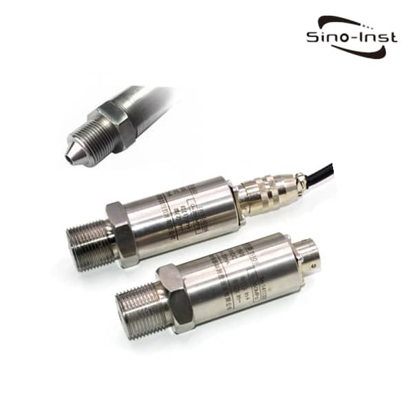
Featured Pressure Transmitters


Pressure Transmitter Working Principle
A pressure transmitter is a device that measures the pressure of fluids or gases in a process and converts it into an electrical signal that can be used for monitoring or control purposes. There are several different working principles that pressure transmitters use to accomplish this:

One of the main components of piezoresistive pressure transmitters is the resistance strain gauge. It is a sensitive device that converts the strain change on the DUT into an electrical signal.
Usually, the strain gauges are closely bonded to the substrate that generates mechanical strain with a special adhesive. When the stress of the substrate changes, the resistance strain gauge also deforms together. Change the resistance value of the strain gauge, so that the voltage applied to the resistance changes. The transmitter has extremely low price and high accuracy and good linearity characteristics.

Diffused silicon pressure transmitters were introduced in the mid-1990s. It utilizes the piezoresistive effect of elastic elements. When the pressure of the measured medium directly acts on the diaphragm of the sensor, the diaphragm produces a micro-displacement proportional to the pressure of the medium, which changes the resistance value of the sensor. This change is detected electronically. And convert and output a unified standard signal.
Compared with traditional products, this transmitter has the advantages of advanced technology, reliable performance, convenient installation, high accuracy and small size.
Corrosion-resistant ceramic pressure transmitters have no liquid transfer. When the pressure acts on the ceramic diaphragm, the diaphragm will produce a slight deformation. Make the thick film resistor printed on the back of the ceramic diaphragm pass through the Wheatstone bridge (closed bridge) connected to it. Output a voltage signal proportional to the excitation voltage.

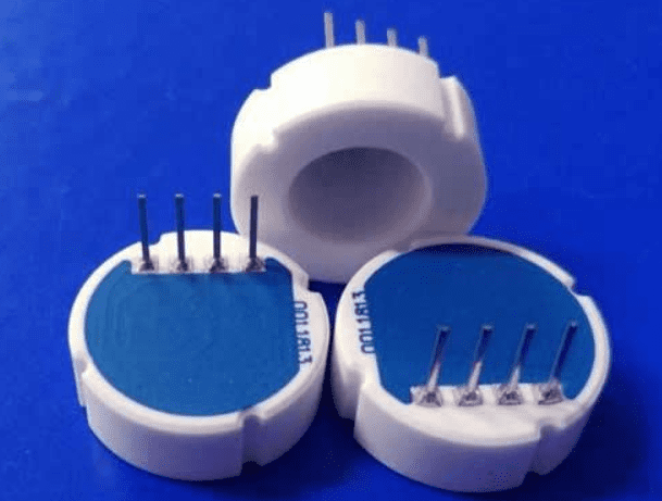
The pressure physical quantity is measured through the built-in circuit of the transmitter and converted into a unified standard signal.
The transmitter can introduce various media (corrosive and non-corrosive gases, liquids) directly to the ceramic diaphragm.
The thermal stability of the ceramic and its thick-film resistance allow it to operate over a temperature range as high as -40°C to 135°C.
Therefore, it has high measurement accuracy, good stability, strong output signal and low price.
Piezoelectric pressure transmitters work on the piezoelectric effect.

The crystal is anisotropic, and when a force is applied along a certain direction, the crystal can produce an electric effect. When the mechanical force is removed, it will return to the uncharged state again. The piezoelectric materials mainly used in sensors are quartz, sodium potassium tartrate and ammonium dihydrogen phosphate.
The transmitter is mainly used in the measurement of acceleration and pressure. It has the characteristics of simple structure, small size, light weight and long service life. But it can only be used to measure dynamic stress.
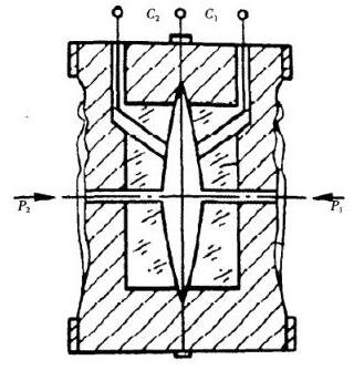
The capacitive pressure transmitter is composed of a measuring diaphragm and electrodes on both sides of the insulating sheet to form a capacitance.
When the pressure on both sides is inconsistent, the displacement of the measuring diaphragm is proportional to the pressure difference. Therefore, the capacitance on both sides is not equal.
Through the oscillation and demodulation link, it is converted into a signal proportional to the pressure. Then the pressure physical quantity is measured and converted into a unified standard signal through the transmission circuit.
It has high precision, corrosion resistance, pollution resistance and good stability. It is recognized as an ideal instrument for detecting low vacuum pressure at home and abroad. It is mainly used in various fields of civil industry, and plays a unique role in military industries such as aerospace industry and nuclear industry.
Extended Reading: Smart pressure transmitter


Video source: https://www.youtube.com/embed/QrT8VWxdxwk?rel=0
Read more about: How does a differential pressure transmitter work

Pressure transmitter signal output


There are three common signal outputs that pressure transmitters provide: millivolt, amplified voltage, and 4-20mA.
Below is a summary of the outputs and when they are best used.
Millivolt Output:
This type of output signal is a low-level voltage signal that is proportional to the pressure being measured. The signal typically ranges from 0-50mV or 0-100mV, depending on the specific pressure range being measured.
This type of output signal is usually used in applications where the signal needs to be amplified or converted to a different format before it can be used by the control system.
Amplified Voltage Output:
This type of output signal is a higher-level voltage signal that has been amplified to a specific range, such as 0-5V or 0-10V.

The voltage signal is proportional to the pressure being measured and can be used directly by the control system without the need for additional signal conditioning.
Amplified voltage output signals are commonly used in applications where the control system requires a voltage input signal.
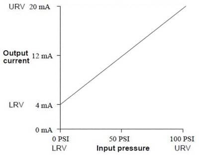
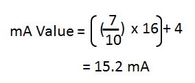
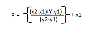
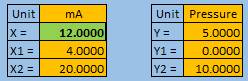
4-20mA Output:
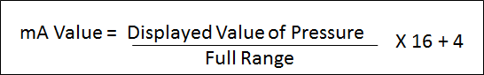
This type of output signal is a current signal that ranges from 4mA at zero pressure to 20mA at the maximum pressure being measured.
This type of signal output is popular because it is immune to electrical noise and can be transmitted over long distances without signal degradation.
4-20mA output signals are commonly used in industrial applications where the control system requires a current input signal.
The choice of signal output will depend on the specific requirements of the application, such as the distance between the pressure transmitter and the control system, the required accuracy and resolution, and the environmental conditions.
Extended reading: Pressure indicator transmitters
Read more about: What is industrial pressure transmitter?
How to Choose Pressure Transducer
There are multiple types of pressure transducers for a variety of applications.
Each pressure transducer has different aspects, that will impact how it works and the applications the pressure transducer works best for.
When selecting a pressure transducer, keep these 6 criteria in mind:
- Application and measurement type
- Pressure range
- Process media
- Temperature range and installation environment
- Accuracy
- Output
If you still don’t know how to choose the pressure transmitter, please contact our sales engineers.


how to use a pressure transducer?
Once you receive the pressure transmitter you ordered, you are ready to use it. First, please check the instruction manual configured by the manufacturer. Based on our many years of experience at Sino-Inst, you can start using a pressure transmitter by following these steps:
- Confirm parameters: Before use, please confirm whether the model, range, output type (generally 4-20 mA current output or 0-10 V voltage output) and working voltage of the pressure transmitter meet your application requirements.
- Check the appearance: Carefully check whether the transmitter is physically damaged and whether the interface is clean.
- Installation location: Install the pressure transmitter on the pipe or container that needs to be measured, ensuring that it is installed securely. Usually the pressure interface should be vertical to the ground.
- Connect the power supply and output: According to the instructions of the pressure transmitter, connect the power cord and output cord. Current-type transmitters need to be connected in series in the control loop, and voltage-type transmitters need to be connected in parallel on the measuring equipment.
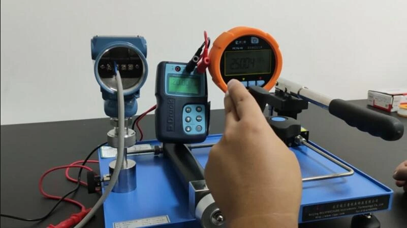
- Zero point calibration: Perform zero point calibration in a no-pressure state to ensure that the output of the transmitter is 4 mA or 0 V when there is no load.
- Testing and debugging: Turn on the power and gradually increase the pressure. Observe whether the output signal changes linearly with pressure. Adjust settings until the transmitter’s output meets operating requirements.
- Record data: Record the output current or voltage value under different pressures. To ensure that the pressure transmitter can accurately reflect pressure changes throughout the entire working range.
- Periodic calibration: Check and calibrate the pressure transmitter regularly to ensure its accuracy and stability in long-term operation.
Can a pressure transducer be used to measure volume?
Pressure transducer cannot be used to directly measure volume. Pressure transmitters are used to measure medium pressure.
However, we can also calculate the volume indirectly through measurements from a pressure transmitter. But this requires other parameters.
For example, in a closed tank, if the temperature of the gas can be kept constant. Then measuring the pressure of the gas can be used to calculate the volume of the gas. This is based on Boyle’s law, which states that the pressure of a gas is inversely proportional to its volume.
Or, in some liquid tanks, if the tank is regular, then we can calculate the cross-sectional area of the tank. Then by measuring the pressure at the bottom of the container, we can calculate the volume of the liquid. Our volumetric recorders also enable this conversion.
Our Pressure Transmitter Markets and Applications
Small Pressure Transducer/Sensor-Low Cost-High Performance
What’s the Difference Between a Pressure Transducer and a Pressure Switch?
What Is Flush Diaphragm Pressure Transducer? When Use?
Natural Gas Pipeline Monitoring: Pressure-Temperature-Flow
Different Types of Pressure: Absolute, Gauge, Sealed Gauge and Differential Pressure
Static Pressure Sensor and Transmitter Features and Applications
Pressure Transducer Price
There are a number of factors, that will impact the price of a pressure transducer.
The biggest differentiator is whether you can use a standard, off-the-shelf pressure transducer or if you need a custom pressure transducer.
For an off-the shelf pressure transducer, pressure transducer prices will be most affected, by the level of accuracy required for your application.
The more accurate, typically the more expensive the pressure transducer.
Extended reading: What is a pressure sensor?
Choose the right pressure transducer for your application
Sino-Inst offers over 20 Pressure Transmitters. A wide variety of Pressure sensors options are available to you. Such as free samples, paid samples. Sino-Inst is a globally recognized manufacturer of Pressure sensors, located in China.
Sino-Inst sells through a mature distribution network that reaches all 30 countries worldwide. Pressure sensors products are most popular in Europe, Southeast Asia, and Mid East. You can ensure product safety by selecting from certified suppliers. With ISO9001, ISO14001 certification.
Request a Quote


Wu Peng, born in 1980, is a highly respected and accomplished male engineer with extensive experience in the field of automation. With over 20 years of industry experience, Wu has made significant contributions to both academia and engineering projects.
Throughout his career, Wu Peng has participated in numerous national and international engineering projects. Some of his most notable projects include the development of an intelligent control system for oil refineries, the design of a cutting-edge distributed control system for petrochemical plants, and the optimization of control algorithms for natural gas pipelines.