
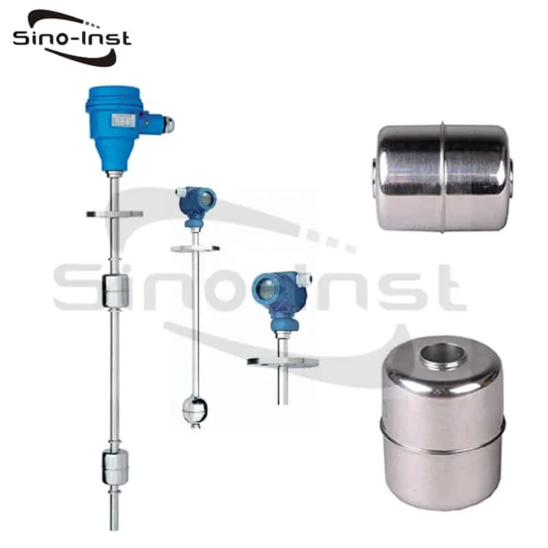
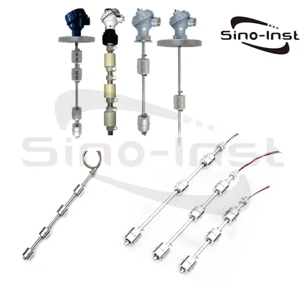
Float Switch Water Level Controller for Continuous Liquid Level (interface) Measurement and Automatic Control. Explosion-proof and water proof.
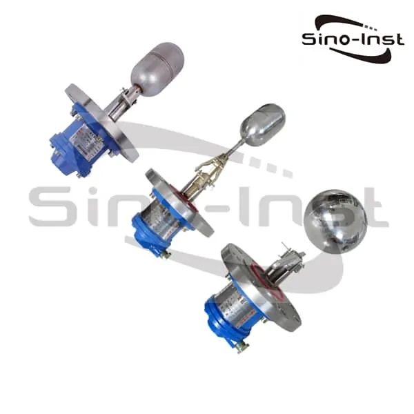
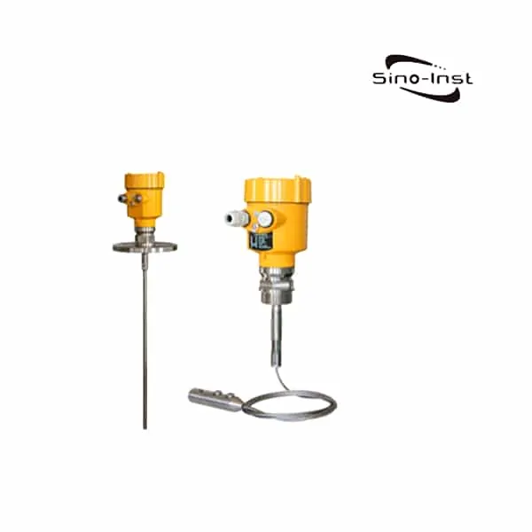
SI-U03 Float Switch Water Level Controller
Float switches, also known as float level switches. Float Switch Water Level Controller is mechanical water level indicators that depend on moving parts to trigger a switch.
Float switch water level controller can be directly installed on various tank equipment (water tank). Float switch water level controller is especially suitable for hot heavy oil in oil refinery (temperature ≤500 ℃, pressure ≤4.0MPa). Viscous and dirty media, asphalt, grease and other oil products. As well as flammable, explosive, corrosive and other media’s Liquid level (interface) continuous measurement and automatic control.
Please feel free to contact us for Techinical Support, or Request a quote for float level sensors (customization available).
Float Switch Water Level Controller Features
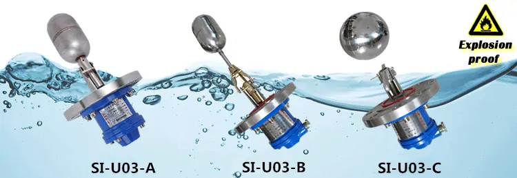
Specifications of SI-U03 Float Switch Water Level Controller
| Type | SI-U03-A | SI-U03-B | SI-U03-C |
| Protection level | dIIBT4 | dIIBT4 | dIIBT4 |
| Pressure | 1.0 MPa | 1.0 MPa | 1.0 MPa |
| Tenperature(℃) | Normal:≤100℃ High Temperature:≤350℃ | ||
| Net weight | 1.5~2.0Kg | ||
| Switching difference(mm) | ≤8 | 25~550 | 8~1000 |
| Setting method | Not adjustable | Stepwise adjustable | Stepless adjustable |
| Installation form | Horizontal | Horizontal | Vertical |
| Power supply and contact capacity and life | AC:220V/1.5A、110V/2.5A DC:24V/2.5A、240V/0.5A Life:5×100^2 |
Know more about: Guide for Liquid level float switches
How to install float switch in water storage tank?

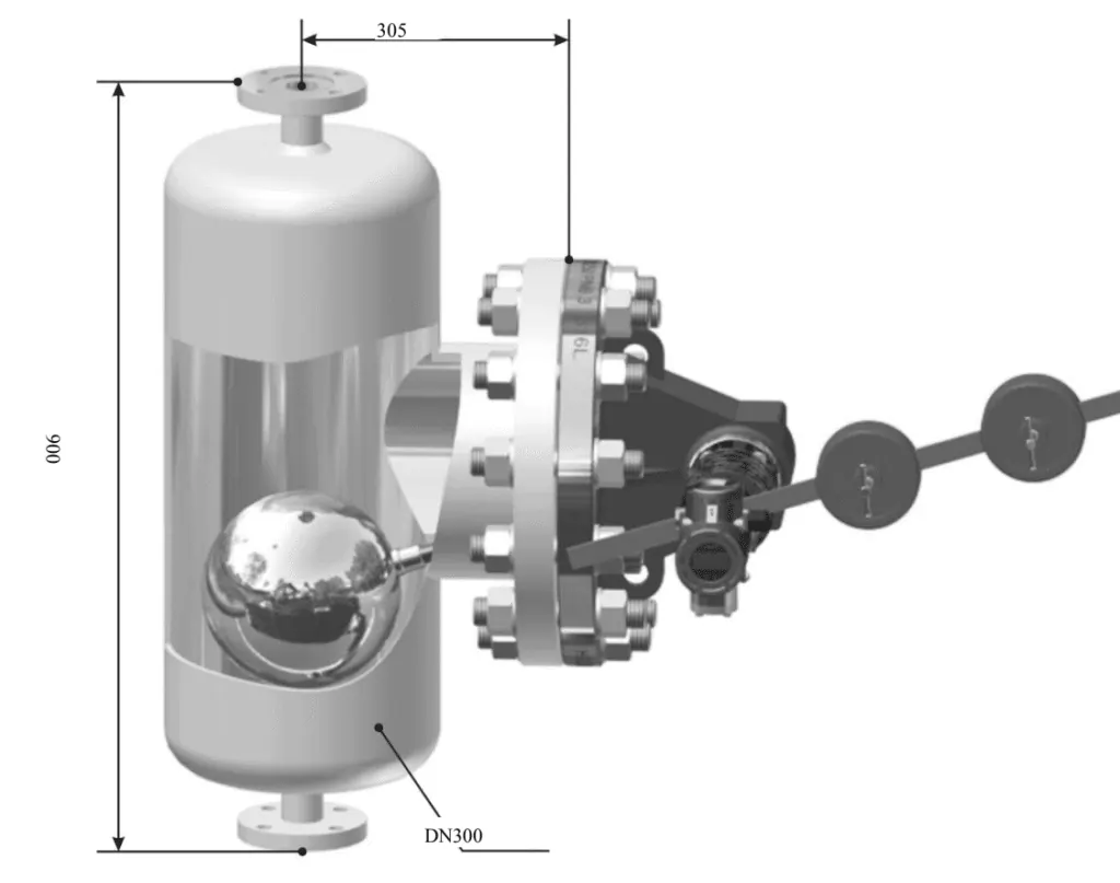
- The flange of SI-U03 series electric float liquid level transmitter is installed on the side wall of the medium tank.
- Before installation, it should be considered in combination with the structural characteristics of the transmitter. It is convenient to operate, observe and maintain to determine the installation position and direction. If the floating ball transmitter is installed on the left side of the flange, it is installed on the left side, otherwise it is installed on the right side.
- Assume that the current state is the right installation. If you want to change to the left installation, use the HART Communicator to move or set the transmitter’s zero position and range.
- And (PV range), follow the prompts on the HART communicator display to enter URV (upper range value). LRV (lower range value). And display USL (upper sensor limit)With LSL (Low Sensor Limit). Reset the lower range value corresponding to 4mA and the upper value corresponding to 20mA and send it. If other parameters are not changed, you can change to the left installation.
- Floating ball and club installation: First, the floating ball and the club are tightened and welded. For the club installation operation of the new connection structure of SI-U03-A small-angle floating ball liquid level transmitter, the club is installed. Screw into the inner screw hole of the connecting rod at the end of the protective rod sleeve.
- Pay attention to tighten the top wires on both sides of the connecting rod into the annular grooves on the club. And then tighten the lock nuts on the top wire. For SI-U03-B large-angle floating ball liquid level transmitter, screw the ball into the inner screw hole at the end of the swing arm. And then tighten the top wire and lock nut on it in the same way.
- Note: “If the site conditions are poor, in order to prevent the floating ball, club, swing arm and other connecting parts from loosening. It is recommended to place the top wire and the lock nut on the joint and tighten the float and the club After welding directly to the coupling. “
- The transmitter is directly installed on the flange of the side wall of the medium container under test through a flange. The requirements for the straight pipe section of the connection flange are as follows: SI-U03-A L ≤ 160mm;
- The transmitter head is connected to the radiator through the connection plate. When installing, insert the spindle head into the coupling hole of the transmitter head, and the coupling should not be distorted. The meter head can be installed on the left or right side.
- For correct installation, please refer to the indicator dial on the back of the transmitter case. If the transmitter is installed on the left, turn the end pointer behind the meter head to the “left 0” scale. If the transmitter is installed on the right side, turn the pointer on the back of the meter to the “right 0” scale line. And when the float is moved to the lowest measurement position, tighten the set screw of the coupling and the spindle.
- Install the balance rod (mechanism) into the dental insert and square hole. Tighten the top wire to fix the balance rod. Loosen the shaft nut and adjust the dental insert to make the balance rod and the ball in the same plane. And put the axial head nut.
- Tighten the position of the balance weight and adjust the balance weight to the optimal state to fix the balance weight. Note: “For liquids of different densities due to the different buoyancy forces experienced by the float, the balance can be adjusted. The position of the hammer on the balance bar to achieve the goal of normal measurement. “
- In the process of adjusting the balance weight, when the feel is light, you can adjust the two M10 compression bolts of the waist-shaped compression sleeve inside the radiator to tighten the expansion force of the sealing gasket. Otherwise, you can adjust the waist-shaped compression sleeve when the feel is light Two M10 bolts loosen the expansion of the gasket until it does not leak!
How does a float switch water level controller work?
The float ball level switch structure is mainly designed and produced based on the principles of buoyancy and static magnetic fields. The position of the floating ball with a magnet (floating ball for short) in the measured medium is affected by buoyancy. The change of the liquid level causes the position of the magnetic float to change. The magnet in the float and the sensor (reed switch) function to generate a switching signal.
Similar to the principle of the float level sensor. But the float level sensor outputs a quasi-continuous electrical signal, while the float level switch outputs a discrete switching signal.
Water Tank Level Controller
Water level controller refers to the control of high and low water levels by mechanical or electronic methods. It can control solenoid valves, water pumps, etc., and become water level automatic controllers or water level alarms. To achieve semi-automation or full automation.
Water level control is generally used for high-level tank water supply and sump drainage. The device that converts the water level signal into an electrical signal to control the start and stop of the water pump is called a water (liquid) level controller.
Commonly used water (liquid) level controllers include reed switch water level controllers, float magnetic switch liquid level controllers, electrode type water level controllers, pressure type water level controllers, etc.
Read more about: Types of water level controllers
Water Level Sensors for Water Tanks
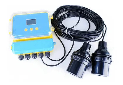
Water level transducers are also called Water Level Sensors, or water level transmitters. Water level transducers are used to monitor water usage and quality. The water level signal is output through 4-20mA and other signals, which is convenient for people to monitor the water level.
There are many types of water level transducers. Common ones are input type, ultrasonic, radar and so on.
Sino-Inst offer a wide range of solutions with various pressure ranges, cable lengths and output options.
For remote monitoring and recording of water level data in groundwater pumping and sludge testing, stormwater flood analysis and runoff, and surface water irrigation canals, streams and river measurements.
Read more about: Types Of Water Level Sensors
Water Tank Level Control System
Water level control refers to the control of high and low water levels by mechanical or electronic methods. It can control solenoid valves, water pumps, etc. to become an automatic water level controller or water level alarm, thereby realizing semi-automation or full automation.
Water level control is generally used for high-level tank water supply and sump drainage. The device that converts the water level signal into an electrical signal to control the start and stop of the water pump is called a water (liquid) level controller. Commonly used water (liquid) level controllers include reed switch water level controllers, float magnetic switch liquid level controllers, electrode type water level controllers, pressure type water level controllers, etc.
Read more about: Water tank level sensor system
Frequently
Asked
Questions
Related Products
Technical Support
Sino-Inst offers over 10 Float Switch Water Level Controllers for level measurement. About 50% of these are liquid Float Switch Water Level Controllers, 40% is the tank level sensor.
A wide variety of Float Switch Water Level Controllers options are available to you, such as free samples, paid samples.
Sino-Inst is a globally recognized supplier and manufacturer of level measurement instrumentation, located in China.
Request a Quote

Wu Peng, born in 1980, is a highly respected and accomplished male engineer with extensive experience in the field of automation. With over 20 years of industry experience, Wu has made significant contributions to both academia and engineering projects.
Throughout his career, Wu Peng has participated in numerous national and international engineering projects. Some of his most notable projects include the development of an intelligent control system for oil refineries, the design of a cutting-edge distributed control system for petrochemical plants, and the optimization of control algorithms for natural gas pipelines.