Remote Magnetic Sewage Flow Meter

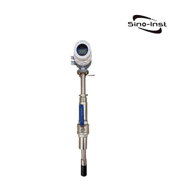
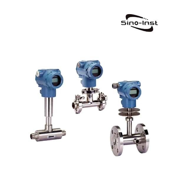
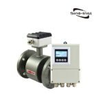
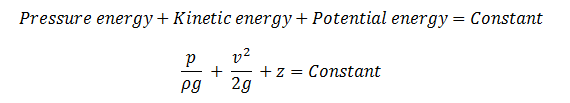
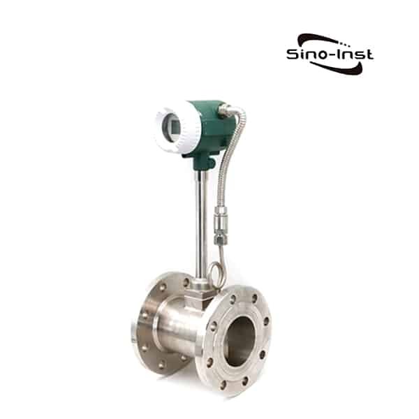
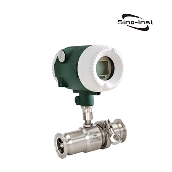
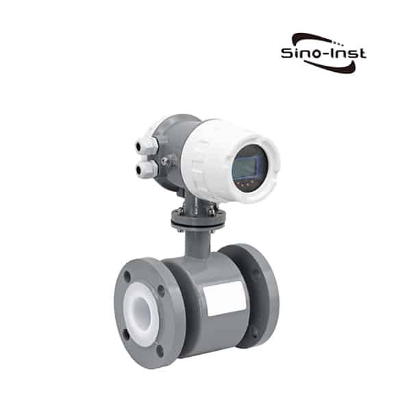
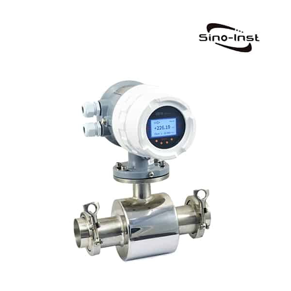
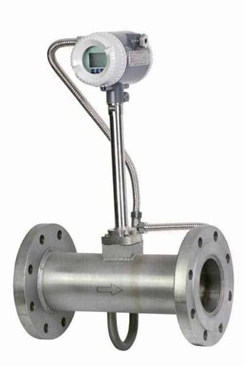
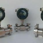
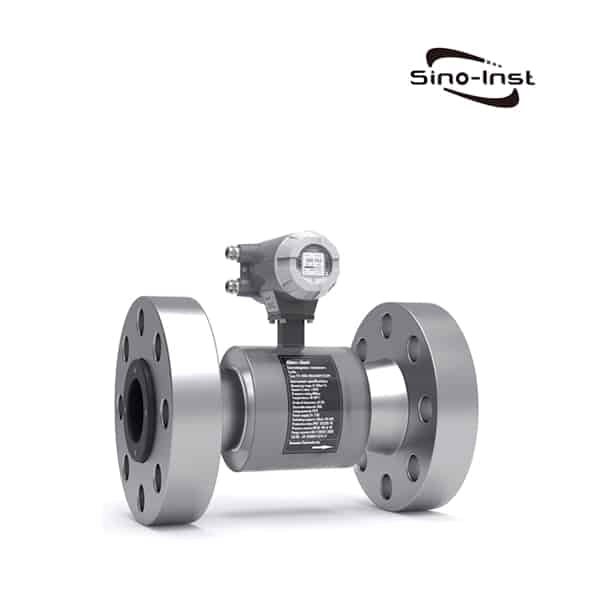
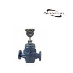
Sewage Flow Meter is an electromagnetic flow meter used to measure sewage/waste water. Also called Effluent flow meter, or wastewater flow meter.

Remote Magnetic Sewage Flow Meter

Sewage Flow Meter application for water flow rate measurement, in those wastewater treatment industrial pipes. The water and sewage treatment industry plays an important role in providing high-quality water supply. In the water treatment process, no matter it is water inlet, transportation, drainage and other processes, the flow needs to be measured. Therefore, the choice of flowmeter is particularly important.

Sewage has the characteristics of large flow rate changes, impurities, high corrosiveness, and certain conductivity. Electromagnetic flowmeter has the advantages of wide range, simple structure, no moving parts, and can measure dirty and corrosive media. Therefore, in the sewage treatment industry, electromagnetic flowmeters are widely used. Here you can find the right sewage flow meter to measure the flow of wastewater for your application.

Sino-Inst offers a variety of  Magnetic Flow Meters for flow measurement. If you have any questions, please contact our sales engineers.

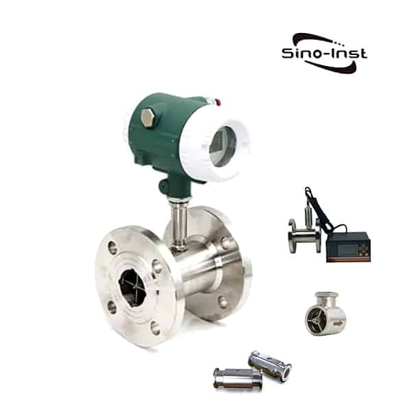
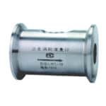
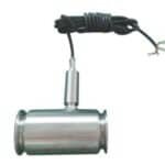
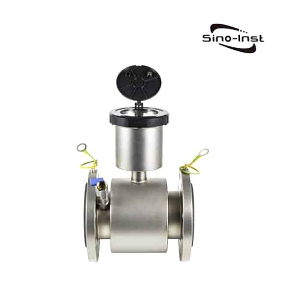
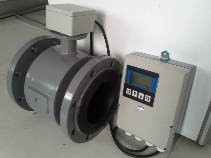
Features of Remote Magnetic Sewage Flow Meter

  • Electromagnetic flowmeter is an instrument for measuring volumetric flow. Flow measurement is not affected by changes in fluid density, viscosity, temperature, pressure and conductivity. The sensor induced voltage signal has a linear relationship with the average flow rate, and the measurement accuracy is high.
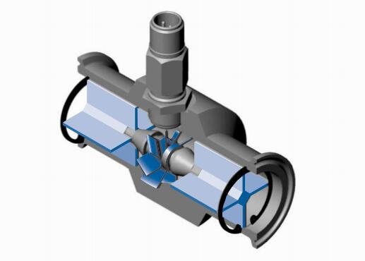
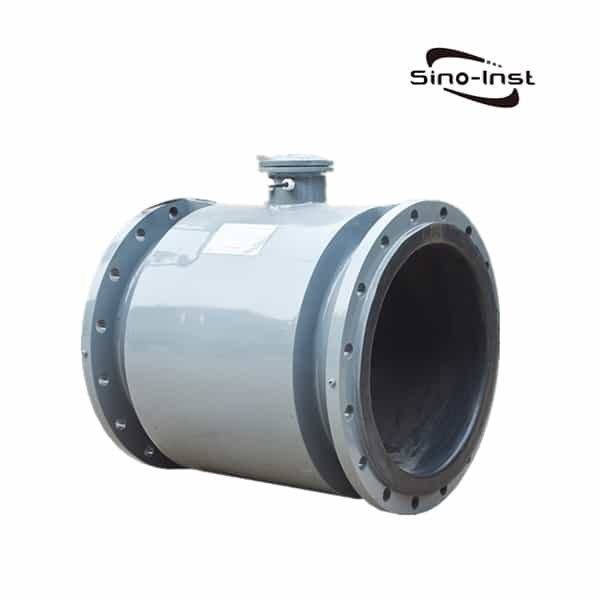
  • There are no obstructions and moving parts in the measuring tube, which will not cause additional energy loss or blockage. Therefore, the energy-saving effect is significant, and it is especially suitable for the measurement of liquid-solid two-phase flow such as sewage, mud, mineral pulp, coal water slurry, paper pulp, etc.
  • The electromagnetic flowmeter has no mechanical inertia and is sensitive. It can measure instantaneous pulsating flow and has good linearity.
  • Installation requirements are low. The straight pipe section required by the sensor is relatively short, generally the first 5D and the rear 3D (D is the inner diameter of the selected instrument).
  • The sensor part only has the lining and the electrode in contact with the medium. As long as the electrode and the lining material are selected reasonably, it can resist corrosion and abrasion, ensuring long-term use.
  • When the power is off, the EEPROM can protect the set parameters and accumulated values.
  • The converter uses a low-power single-chip microcomputer to process data. It uses SMD electronic components and surface mount SMT technology. Reliable performance, high precision, low power consumption, and zero point stability. LCD display, display cumulative flow, instantaneous flow, flow rate, flow percentage and other parameters.
  • It adopts multi-electrode structure with high accuracy. Equipped with ground electrode, no grounding ring is needed, which saves cost.
  • The low-frequency rectangular wave excitation improves the stability of the flow. The power loss is low and the low flow rate is superior.
  • Two-way measurement system. It can measure forward flow and reverse flow.

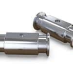
Specifications of Remote Magnetic Sewage Flow Meter

CaliberDN 10 ~ DN2000 (3/8″…80″)
Excitation methodSquare wave constant current excitation
Installation formOne-piece flange, split flange
liningNeoprene, polyurethane rubber, PTFE, F46
Electrode material316L, Hc, Hb, titanium, tantalum, platinum iridium, tungsten carbide
GroundBuilt-in ground electrode (DN25 and above)
MediumConductive liquid
level of accuracy0.5, 1.0
Dielectric conductivity> 5 μS/cm
Flow rate≤ 10 m/s
Pipe connection flangeGB 81~59
Pipe connectionFlange connection
Medium temperatureChloroprene rubber: -10℃~60℃; PTFE: -10℃~120℃
Polyurethane rubber: -10℃~80℃; F46: -10℃~150℃
preset pressure4.0 MPa; 1.6 MPa; 1.0 MPa
Protection levelIP65; IP68
output signal4mA ~ 20mA DC current; pulse/frequency; upper and lower limit alarm
Cable interfaceM20×1.5 internal thread
CommunicationRS 485 communication protocol (modbus protocol)
RS 232 communication protocol (optional)
DisplayInstantaneous flow, alarm display, percentage, flow rate, forward and reverse cumulative flow and total cumulative
power supply220V AC, 24V DC, 3.6 V battery power supply
Use typeOrdinary type, waterproof type
High pressurecustom made

Read more about: Digital Water Flow Meters

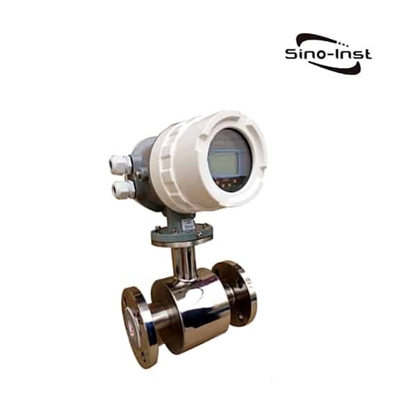
Electromagnetic Flow Meter for Sewage

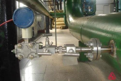
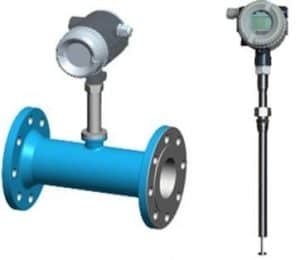
According to the situation of the wastewater treatment site, there are two general wastewater discharge methods. One is to discharge through pipes, and the other is to discharge through ditches. The two types of flow meters selected are therefore different.

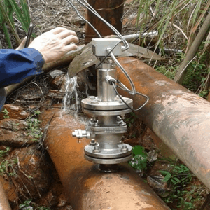
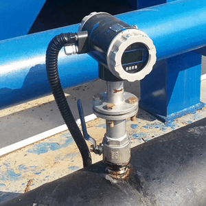
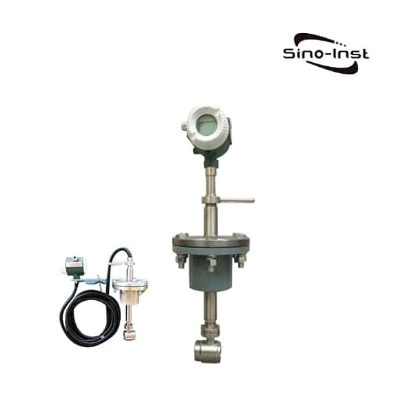
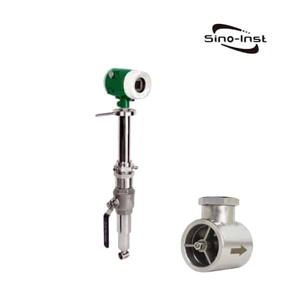
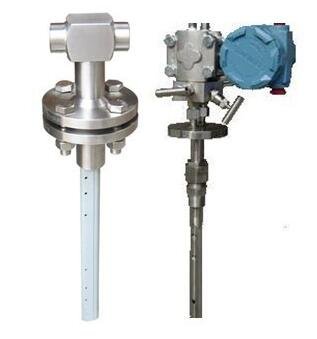
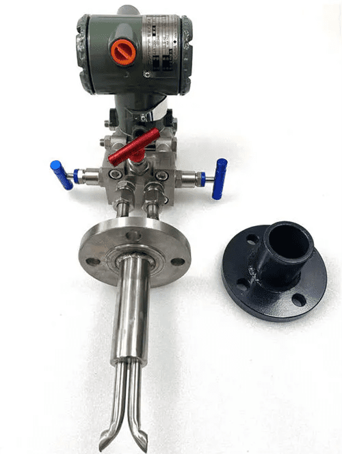
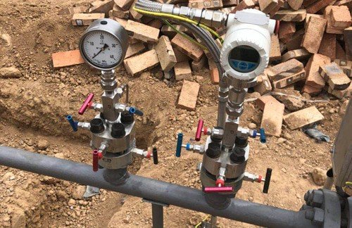
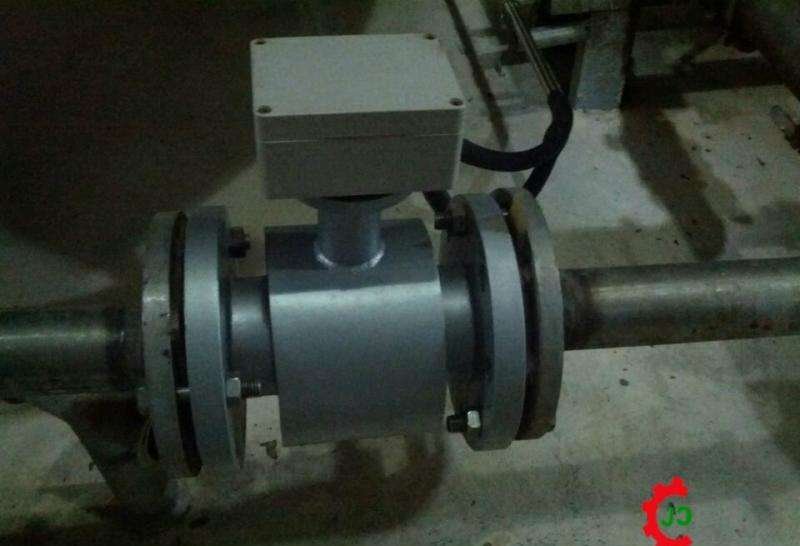
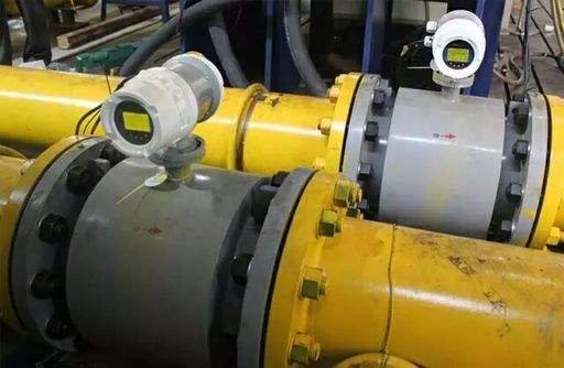
1.Waste water is used for pipeline discharge, and most of them choose electromagnetic flowmeter to measure. Because there are no obstructions in the sensor, there is no fear of debris in the medium.

But need to pay attention to the medium must be full. If the pipe is not full, a pipe must be used to lead a section of the sinking pipe to ensure that the flowmeter is in a full pipe.

Note that the electromagnetic flowmeter cannot be installed at the drain of the pipeline, and the length of the straight pipe must meet the requirements of the flowmeter.

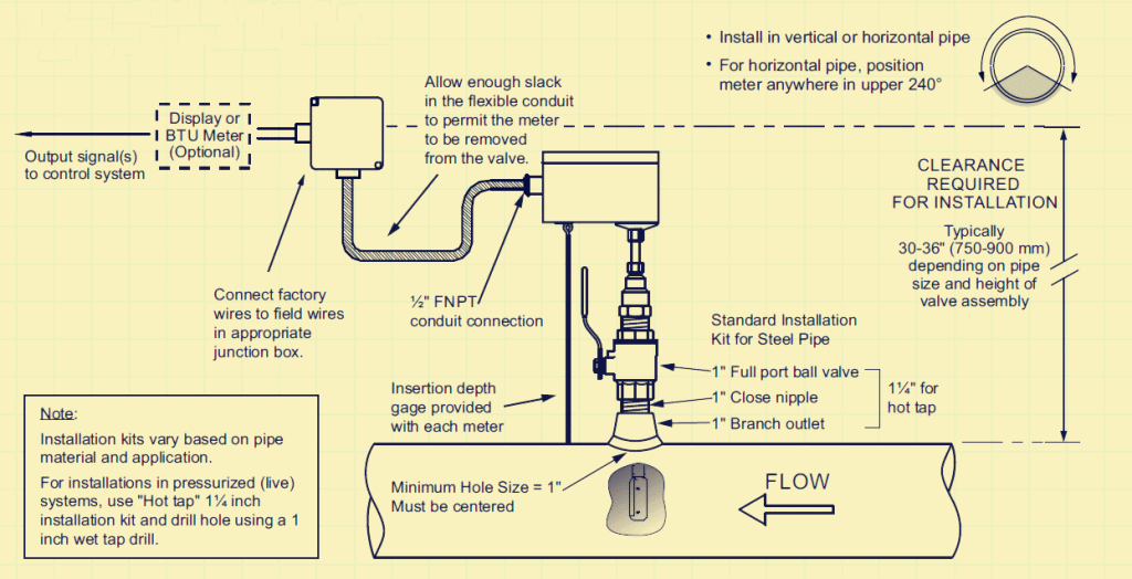
Extended Reading: Guide: Magnetic Flowmeter Installation

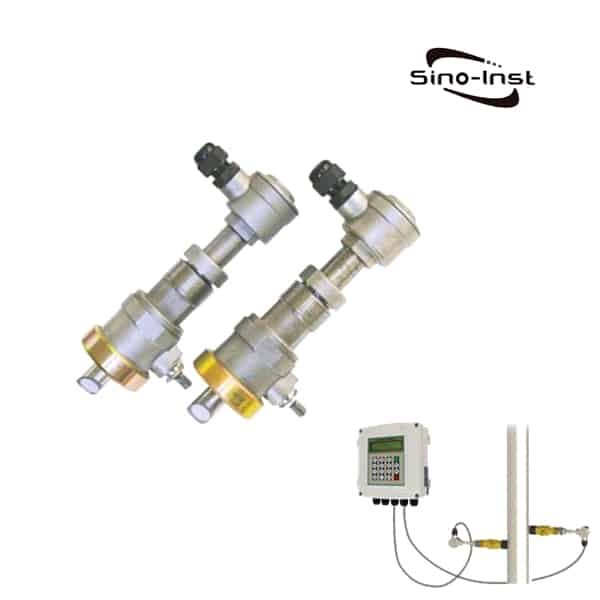
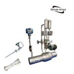
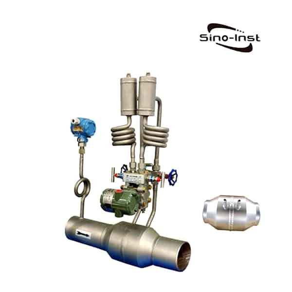
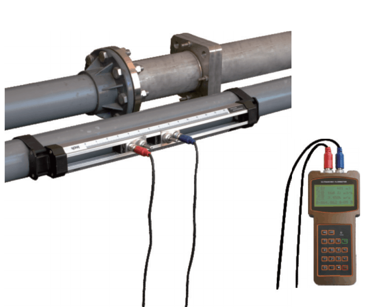
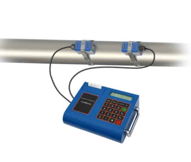
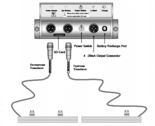
2.Wastewater is used for ditch discharge, mostly using ultrasonic open channel flow meters.

A measuring groove is installed at the discharge port, and an ultrasonic probe is installed directly above the groove. In this way, the flow of wastewater flowing through can be measured. This instrument generally uses 24V power supply, output: 4-20MA.

When selecting the electromagnetic flowmeter for waste water, it is necessary to know the temperature of the medium, the pressure of the medium, the flow range of the medium, the composition of the medium, the power supply requirements, and the on-site installation requirements. The key point of the selection is to choose which product to measure well. The second is to consider the convenience of installation, operation and maintenance. Finally, the product price can be considered.

Read more about: Sewage flow meters|Waste water measurement

Wastewater/Sewage Flow Meter Calibration

A flow meter’s deviation from the standard can be measured in two ways: with a master meter or by weighing mass flow.

Master meters are calibrated to peak accuracy by specified, accredited laboratories.

These labs are ones that are certified by the National Institute of Standards and Technology (NIST). Subsequently, this means that flow meters. Which are calibrated to master meter accuracy in such a lab will be backed by NIST certification and traceability.

The second method of flow meter calibration involves weighing the amount of fluid that flows through the meter, during the calibration procedure. This is typically done using a supremely accurate weigh scale, which must also be approved by NIST.

This method is often regarded as the most accurate way to measure the volume of flow.

Flow meters can also be calibrated in the field, also known as “wet” calibration.

However, this method is frequently scrutinized because it lacks the involvement of national standards.

Additionally, field calibrations are usually not an option in most applications. Because challenging an installed flowmeter with a given volume of water is just not practical.

You may like:

Featured Sewage Flow Meters

Sino-Inst offer over 20 Sewage flow meters, with Best Price.

A wide variety of Sewage Flow Meters options are available to you, such as free samples, paid samples.

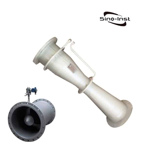
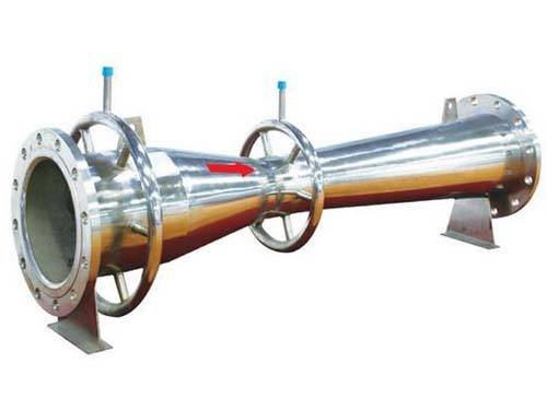
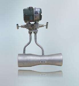
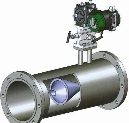
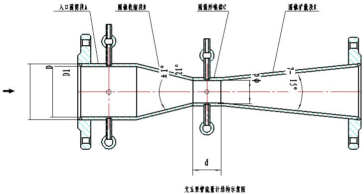
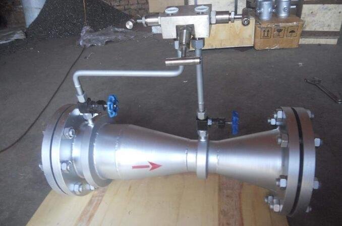
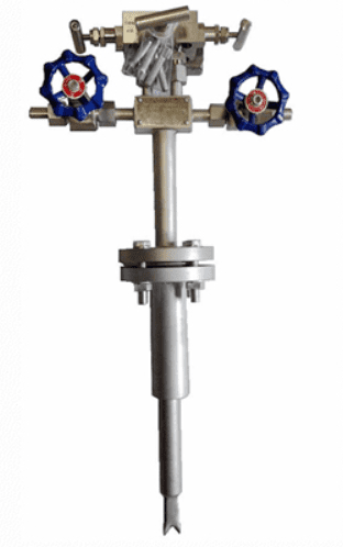
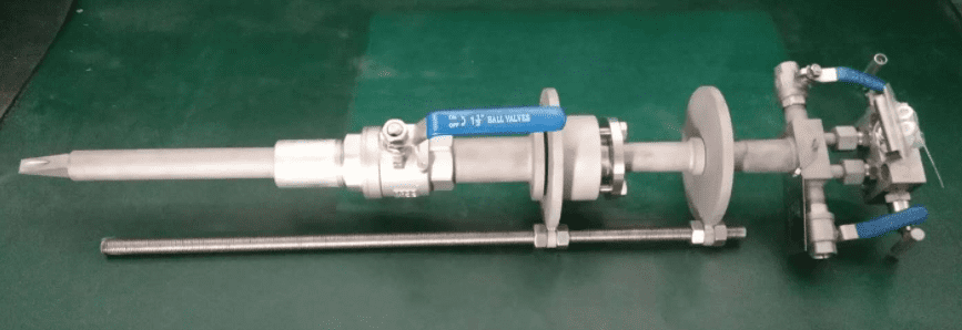
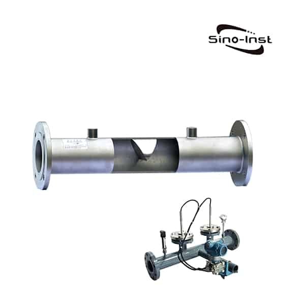
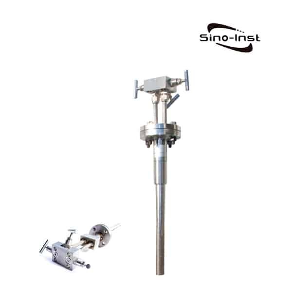
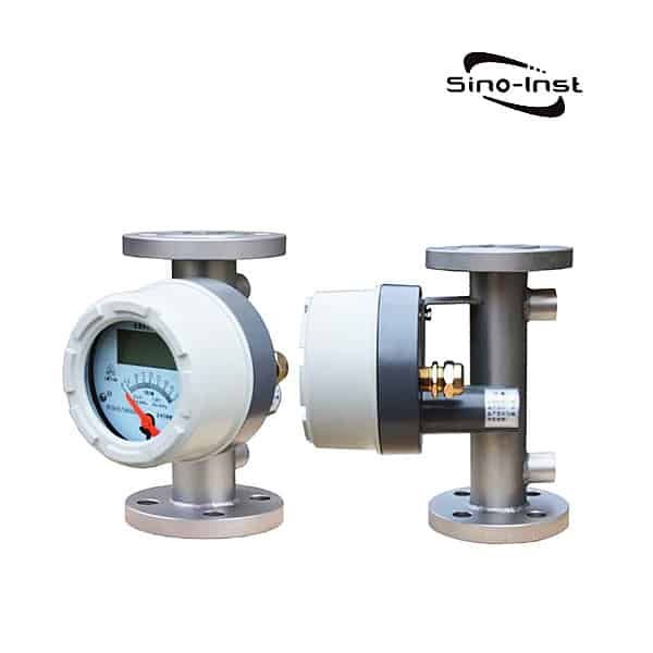
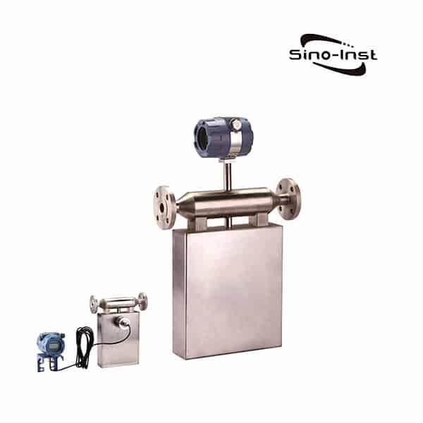
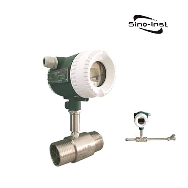
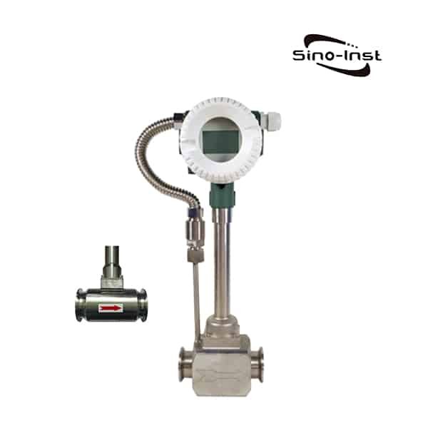
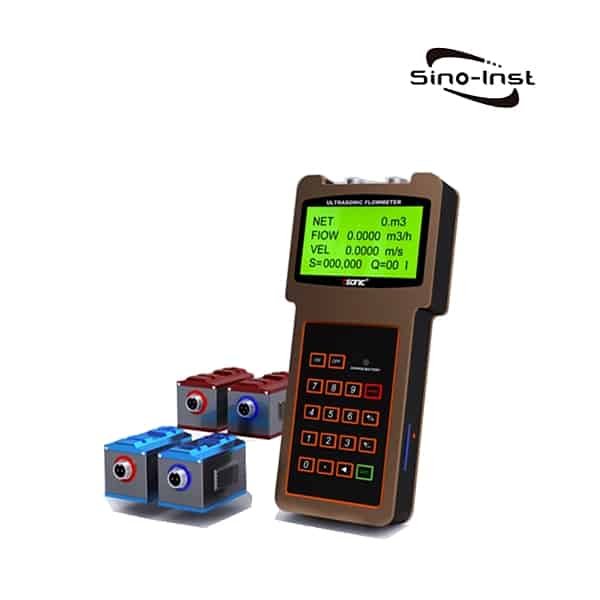
About 13% of these are magnetic flow meter, 14% are Insertion Magnetic Flow Meter, 25% are Venturi flow meter, 13% are Handheld ultrasonic flow meter, and others are Liquid Turbine Flow Meters.

Sino-Inst is Sewage Flow Meters suppliers, located in China. Sewage Flow Meters products are most popular in North America, Mid East, and Eastern Europe. The United States, and India, which export 99%, 1%, and 1% of ultrasonic level transmitter respectively.

Request a Quote

Insertion Magnetic Flow Meter

Insertion Magnetic Flow Meter, also called insertion electromagnetic flow meter, is an insertion type flow meter. Insertion magnetic flowmeter can be installed without stopping the flow. Suitable for large diameter DN300-3000.

Insertion Magnetic Flow Meter adopts pressure tapping and installation technology. Insertion electromagnetic flow meter is composed of insertion electromagnetic sensor and electromagnetic flow converter.

Installation can be divided into an online installation type of the cut-off valve, and water control installation type without stop valves. The Insertion Magnetic Flow Meter is suitable for measuring the volume flow of various conductive liquids in the pipeline. It can also be used to measure corrosive conductive liquids such as acid, alkali and salt.

Sino-Inst offers a variety of  Magnetic Flow Meters for flow measurement. If you have any questions, please contact our sales engineers.

Features of Insertion Magnetic Flow Meter

Compared with the pipe segment electromagnetic flowmeter, the advantages of Insertion Magnetic Flow Meter:

  1. No need to cut off the water, cut off the pipeline, install directly on the old pipeline;
  2. Easy to disassemble during maintenance;
  3. Especially suitable for large-diameter pipelines, with high cost performance;
  4. The accuracy is lower than the flange type, and it is mostly used for process control rather than measurement;
  5. It can be made into one-piece or component pose;
  6. The Insertion electromagnetic structure can be easily installed and disassembled without stopping the water under low pressure or under pressure. Therefore, it is very suitable for the fluid measurement of existing pipelines and facilitates the maintenance and repair of instruments.
  7. The measurement accuracy is not affected by changes in physical parameters such as the temperature, pressure, density, viscosity, conductivity (as long as the conductivity is greater than 20μs/cm) of the measured medium.
  8. The sensor has almost no pressure loss and extremely low energy loss.
  9. Large flow measurement range. The full-scale flow rate in the measured pipe can be set arbitrarily from 1m/s to 10m/s, and the output signal has a linear relationship with the flow rate.
  10. The flowmeter not only has 0~10mA or 4~20mA standard current output, but also 1~5kHz frequency output

Specifications of insertion electromagnetic flowmeter

Medium Water, sewage water, acid, alkali, etc.    
Diameter Dn300~DN3000mm    
Accuracy ±2.5%    
Temp. range -20~+150℃    
Pressure 1.6 MPa    
Flow rate 0.5~6m/s    
Straight pipe required Upstream≥5DN, downstream≥3DN    
Electrode 316L,Hastelloy C(HC), Titanium(Ti), Tantalum(Ta),Platinum(Pt)    
Installation way Without a ball valve or with a ball valve    
Body material Stainless steel    
Power supply 220VAC/24VDC/Lithium battery    
Signal output Pulse output, 4~20mA    
Communication RS485,Hart, GPRS etc.    
Explosion-proof No    
Protection class IP65(compact type), IP68(remote type)    
Working environment Temp. Range: -20~+60℃,  humidity: 5%~90%    

Applications of Insertion Magnetic Flow Meter

  • Potable Water
  • Water Distribution
  • Pumping Stations
  • Filter Balancing and Backwash
  • Reclaim Water
  • Treated Water
  • Irrigation Water
  • Cooling Water
  • Raw Water

Extended reading: 2 inch Water Flow Meter

Insertion magnetic flow meter principle

All MAG Meters operate under the same fundamental principle of classical physics (Faraday’s Law of Electromagnetic Induction):

E = CONSTANT x B x D x V

The law states that the magnitude of the voltage (E) induced in a conductive medium, moving through a magnetic field is directly proportional to the strength of the magnetic field (B), the path length between the probes (D), and the velocity of the medium (V).

In principle and implementation, it is possible to fix all parameters except velocity.

Thus a MAG Meter responds only to “velocity” and is extremely insensitive to changes in fluid conditions (density, viscosity, etc.) and application constraints (pressure, temperature, and mechanical vibrations, as well as fluid pulsation).

The operation of a MAG Meter is completely analogous to an electrical generator.

A voltage is induced in a conductor that is moving at right angles through a magnetic field.

The faster the conductor moves, the more voltage is generated.

You may want to know more about: Magnetic Flow Meters technical guide|What is &How they work? 

Advantages of Magnetic Flowmeters

Electromagnetic (MAG) flowmeters have been widely used in industry for over 50 years.

And for good reason, the advantages of MAG meters are irrefutable.

  • High reliability – no moving parts
  • No scheduled maintenance
  • Good accuracy: 0.5% to 2.0% of reading
  • Very wide range: up to 100:1
  • No pressure drop
  • The wide selection of materials
  • The wide selection of fluids metered

Extended reading: Industrial Magmeters

Typical Installation of Insertion Magnetic Flow Meter

Easy To Install

  1. Place saddle and ball valve
  2. Hot tap
  3. Insert meter and set the depth
  4. Tighten clamp
  5. Provide electrical Ground connection on plastic pipes

Extended Reading: Special Magnetic Flowmeter Installation situation

Choice of installation environment

  1. It should be installed at the lower part of the horizontal pipeline and vertically upwards, avoid installing at the highest point of the pipeline and vertically downwards;
  2. It should be installed on the rising part of the pipeline;
  3. Installation in the open discharge pipe should be installed at the lower part of the pipe;
  4. If the pipeline drop exceeds 5m, install an exhaust valve downstream of the sensor;
  5. The control valve and shut-off valve should be installed downstream of the sensor, not upstream of the sensor;
  6. The sensor must not be installed at the inlet and outlet of the pump, it should be installed at the outlet of the pump.
  7. Keep away from equipment with strong fields, such as large motors and large transformers.
  8. There should be no strong vibration in the installation place, and the pipeline should be firmly fixed. The ambient temperature should not change much.
  9. The installation environment should be easy to install and maintain.

Choice of installation location

The installation location must ensure that the pipeline is always filled with the fluid under test.
Choose a place where the fluid flow pulse is small, that is, away from the pump, valves, elbows and other local resistance parts.

When measuring two-phase (solid, liquid or gas, liquid) fluids, choose a place that is not easy to cause phase separation.

Avoid negative pressure at the measurement site.

The diameter or circumference of the side pipe is easy to measure, and the ovality should be small.

Length of straight pipe

The length of the straight pipe section on the upstream side of the sensor installation pipeline should be greater than or equal to 10D, and the downstream side should be no less than 5D (D is the diameter of the pipeline being tested).

The flow control valve should be installed on the pipe under test on the upstream side of the sensor, and the flow control valve should be installed on the downstream side of the sensor. When measuring, usually the flow control valve should be fully open.

Installation method

Vertical installation, when the sensor is inserted into the pipeline, it should be perpendicular to the central axis of the pipeline, and the included angle with the pipe section is less than 50. It is suitable for measuring clean media with small pipeline vibration.

There are two ways to insert the insertion point of the electromagnetic flow sensor. One is to insert at 1/4 of the inner diameter of the pipe. The other is to insert at 1/2 of the inner diameter of the pipe.

Correctly weld the mounting base to the pipe. Clean up welding slag and burrs on the mounting base of the pipe under test.

Turn off the upstream flow control valve or use a low-pressure water supply.

Install the DN50 ball valve on the mounting base. Note that the long cavity of the ball valve faces upwards. Check whether the ball valve can be fully opened and closed. If there is any problem, repair it. Install the compression threaded seat, compression nut and rubber sealing ring on the ball valve. Loosen the positioning screw and the compression nut, and insert the sensor through the ball valve into the pipe under test. Tighten the compression nut and the positioning screw, and at the same time, pay attention to the insertion direction of the sensor direction sign and the fluid flow direction.

Insertion depth

(1) When selecting the electrode to insert to the average flow rate, the average flow rate point is about H=0.25D from the pipe wall (D: pipe inner diameter) according to the pipeline turbulent flow conditions. Press the handle to make the insertion rod enter the pipe H deep. (L2 at this time = original L2-H)

(2) After confirming that the insertion depth is correct, turn the flow direction rod to make its connection parallel to the centerline of the pipeline. At this time, the connection between the two electrodes will be perpendicular to the centerline of the pipeline. That is, the connection between the electrodes is perpendicular to the flow rate.

(3) After adjustment, first tighten the lock nut firmly, and then tighten the three locknuts separately. One of their functions is to ensure that the insertion rod is not pushed out by the pressure in the tube. The other is to ensure that the insertion rod does not vibrate.

(4) During actual on-site installation, the insertion depth is only allowed to be 0.25D, which is a quarter of the diameter of the pipe. The insertion depth is 0.5D, which is the center of the pipe.

(5) Loosen the fastening screws under the junction box. Rotate the junction box to the position you are satisfied with and tighten the nuts.

The Insertion flowmeter is a type of flowmeter divided by structure. It includes various flowmeters with different working principles.

Usually, the flowmeter and the pipeline are flanged. Only when the processing pipeline is cut off is allowed to be disassembled, repaired, and replaced. This has a great impact on the reliable operation of the system. The Insertion flowmeter fundamentally solves this defect. Although the measurement accuracy is slightly lower. But on some large-caliber occasions, Insertion flowmeters have been used to measure the total amount of fluid.

There are many forms of Insertion flowmeters that have been promoted. According to the working principle of Insertion flowmeter detection heads, they can be divided into Insertion turbine, Insertion vortex, Insertion electromagnetic, uniform velocity tube, and thermal flowmeter. The number of measuring points of the Insertion flowmeter can be divided into two categories: point flow type and runoff type.

The accuracy of the magnetic flowmeter has been calibrated by the calibration line when it leaves the factory. However, at the use site, due to environmental conditions, fluid characteristics, and instrument damage such as component damage. It often causes instrument operation failures. Therefore, the electromagnetic flowmeter needs calibration. Ensuring accurate flow meter performance is an inestimable part of business planning and costing.

More Featured Insertion flowmeters

At present, there are many kinds of Insertion flowmeters in use. According to the working principle of the Insertion flowmeter detection head, it can be divided into Insertion turbine, Insertion vortex, Insertion electromagnetic, Insertion ultrasonic, and Insertion target flowmeter.

The correct choice of the flowmeter is of great significance for flow measurement. Choosing different flow meters under the same working conditions will definitely have a considerable difference in the final measurement results.

If the initial selection is improper, it may even lead to the inability to perform quantitative measurements and cause damage to the instrument. Therefore, it is necessary for users to have a correct understanding of how to choose a suitable flow meter. Knowing some basic selection methods will help make mistakes when choosing meters.

In order to ensure the use of the flow meter in the production site process. The choice of flowmeter, in general, must be determined according to the medium that needs to be measured at the production site.

The advantages of the insertion vortex flowmeter are particularly good anti-vibration performance, no zero drift, and high reliability. Through a large number of waveform analyses and frequency spectrum analyses on the vortex flowmeter for a long time, the probe shape, wall thickness, height, probe rod diameter, and matching piezoelectric crystals are designed.

Insertion Vortex Flow Meter

It adopts an advanced numerical control lathe for processing. It ensures the coaxiality and smoothness of processing and other technical parameters and cooperates with special processing. It overcomes the common problem of the influence of the inherent self-oscillation frequency of the vortex flowmeter on the signal.

The insertion vortex flowmeter is mainly used for the flow measurement of large-caliber gas, liquid, and steam medium fluids in industrial pipelines in various industries.

It is characterized by small pressure loss, a large measuring range, and high accuracy. It is almost not affected by fluid density, pressure, temperature, viscosity, and other parameters when measuring volume flow under working conditions.

Insertion ultrasonic flowmeter can be divided into propagation velocity difference method (direct time difference method, time difference method, phase difference method and frequency difference method), beam shift method, Doppler method, and cross-correlation method according to the principle of signal detection. , Spatial filtering method and noise method, etc.

Ultrasonic Insertion Flow Meter

Ultrasonic flowmeters are the same as electromagnetic flowmeters. Because the flow channel of the instrument is not equipped with any obstructions, it is an unobstructed flowmeter. It is a type of flowmeter suitable for solving difficult problems in flow measurement. Especially in large-caliber flow measurement. The advantages.

Insertion ultrasonic flowmeter is mainly used in petroleum, chemical industry, metallurgy, electric power, water supply, and drainage, and other fields.

The structure of the Insertion turbine flowmeter is an explosion-proof design. It can display the total flow, instantaneous flow, and the percentage of flow full scale. The battery adopts a long-term lithium battery. The battery life of a single-function integrator can reach more than 5 years, and the battery life of a multi-function indicator can reach more than 12 months.

Turbine Insertion Flow Meter

Insertion turbine flowmeter can display many flow units, including cubic meters, gallons, liters, standard cubic meters, standard liters, etc. The fixed pressure and temperature parameters can be set to compensate for the gas. For occasions where the pressure and temperature parameters do not change much, the instrument can be used for fixed compensation accumulation.

Insertion turbine flowmeters are mainly used in metering and control systems in the fields of petroleum, chemical industry, metallurgy, scientific research, and so on.

The Insertion target flowmeter is based on the traditional target flowmeter. With the development of new sensors and microelectronics technology, a new type of capacitive force induction flow Insertion target flowmeter has been developed. It has the characteristics that the flowmeter has no movable parts such as an orifice plate and vortex street. At the same time, it has high sensitivity and accuracy comparable to positive displacement flow meters. The measuring range is wide.

Target Flow Meter

Insertion target flowmeter has good adaptability in the working conditions of small flow, high viscosity, easy to condense and easy to block, high and low temperature, strong corrosion, strong vibration and other flow measurement difficulties. Mainly used for flow measurement in various fields such as metallurgy, petroleum, chemical industry, energy, food, and environmental protection.

More Featured Wastewater Flow Meters

More about: Sewage Flow Meter Selection

Sino-Inst offers all kinds of flow meters, which can work for the wastewater.

You may like:

Sino-Inst offers 10 Insertion Magnetic Flow Meters. A wide variety of  Industrial flow meters options are available to you. such as free samples, paid samples.

Sino-Inst is an Industrial flow Transmitter supplier, located in China. The top applying countries are China (Mainland), Hong Kong, and the United States, which supply 96%, 2%, and 1% of wireless pressure transmitters respectively.

Insertion Magnetic Flow Meter products are most popular in North America, Domestic Market, and South America. You can ensure product safety by selecting from certified suppliers, with ISO9001, and ISO14001 certification.

Request a Quote

Please enable JavaScript in your browser to submit the form

Venturi Flow Meter

Venturi flow meter is also called classical venturi, and is used to call venturi meter, standard venturi. It is used to measure the flow of single-phase stable fluid in closed pipelines.

Venturi flow meter is a flow measurement method based on the principle of differential pressure. Commonly used to measure the flow of fluids such as air, natural gas, coal gas, and water. In the standard throttling device, the upstream and downstream straight pipe sections required by it are short. The lasting pressure loss is small, the performance is stable, and the maintenance is convenient.

Sino-Inst, Manufacturer for differential pressure flow meters. Including the Orifice plate, Venturi, Annubar, etc. Suitable for liquid, gas, and steam flow measurement. Please contact our sales engineers for technical support!

Features of Venturi flow meter

  • Less head loss than an orifice or nozzle meter, due to the streamlined design
  • Ideal for clear gas, liquid or steam applications
  • Available in many materials and end arrangements
  • Can be equipped with fittings to accept secondary instrumentation packages

The classic venturi tube is simple, durable and stable in performance.

Classic venturi pressure loss is small, saving the energy needed for fluid delivery.

Classic venturi tube in the range of 50 ~ 1200.

No real-flow calibration is required.

Beyond this range, you can refer to the design and manufacture.

When high precision is required, real-time calibration is possible.

The body is installed in long size, and it is not convenient for transportation and installation for large-diameter instruments.

What is a venturi flow meter?

Venturi flowmeter, also known as venturi tube flow meter. It is a commonly used device for measuring the flow of pressurized pipelines.

It is a differential pressure flowmeter, and is commonly used to measure the flow of air, natural gas, gas, water, and other fluids.

It consists of a “contraction section”, a “throat” and a “diffusion section”, which are installed on the pipe where the flow rate needs to be measured.

The classic venturi tube is designed and manufactured, according to China GB/T2624-93, and is verified according to the verification procedure JJG640-94.

In the standard throttling device, it requires the shortest upstream and downstream straight pipes, the lowest pressure loss, stable performance, and convenient maintenance.

Because of its accurate calculation and low energy consumption, it has been widely used in petroleum, chemical, electric power, and metallurgy industries.

Venturi flow meter parameters:

1. Nominal diameter: 50mm≤DN≤1200mm (more than this range needs to be calibrated)                 

Roughcasting shrinkage section: 100mm ≤ DN ≤800mm                

Mechanical processing shrinkage section: 50mm ≤ DN ≤ 250mm                 

Shrinking section of rough welded iron plate: 200mm≤DN≤1200mm

2. Throttle aperture ratio β: 0.3 ≤ β ≤ 0.75                    

Roughcast shrinkage segment: 0.3 ≤ β ≤ 0.75                   

Machining shrinkage section: 0.4 ≤ β ≤ 0.75                    

Coarse section of rough welded iron plate: 0.4≤β≤0.7

3. Reynolds number range: 2 × 10 5 ≤ ReD ≤ 2 × 10 6                  

Rough cast shrinkage section: 2 × 10 5 ≤ ReD ≤ 2 × 10 6                   

Machining shrinkage section: 2 × 10 5 ≤ ReD ≤ 2 × 10 6                   

Shrinkage section of rough welded iron plate: 2×10 5≤ReD≤2×10 6

4. Accuracy level: 1

Venturi Flow Meter PDF

Classic venturi flowmeter structure

venturi flowmeter structure

The axial section of the classic venturi is shown in the figure above.

It is composed of an inlet cylinder section A, a conical contraction section B, a cylindrical throat C, and a conical diffusion section E.

The diameter of the cylinder section A is D, the length is equal to D. The contraction section B is conical and has an angle of 21 ° ± 1 °. The throat C is a cylindrical shape of diameter d, the length of which is equal to d;

E is conical and has a diffusion angle of 7° to 15°.

The constricted section of the classic venturi is divided into three forms: a coarse cast shrinkage section, a machined shrinkage section, and a coarse welded iron plate shrinkage section.

The upper-pressure port and the throat pressure port of the classic venturi, are made into several (not less than four) separate tube wall pressure ports.

And several separate tube walls are pressure-connected by a pressure-equalizing ring.

When d≥33.3mm, the diameter of the throat pressure port is 4~10mm, the diameter of the upstream pressure port should be no more than 0.1D. When d≤33.3mm, the diameter of the throat pressure port is 0.1d~0.13d. The diameter of the upstream pressure tap is 0.1d to 0.1D.

Extended reading: How to realize the flow accumulation function in PLC?

Venturi meter working principle

Venturi flowmeter working principle

The Venturi flow meter produces a differential pressure, to calculate the flow rate through a pipe.

The meter works by measuring the pressure of fluid before and after it passes through a narrow tube; the pressure difference indicates the volumetric rate of flow.

The basic measurement principle of the new generation, of differential pressure flow measuring instruments, is the flow measurement method based on the law of conservation of energy – the primary effort equation and the flow continuity equation.


The inner venturi consists of a circular measuring tube, and a special core placed in the measuring tube and coaxial with the measuring tube.

The outer surface of the special core has a geometric profile, similar to the inner surface of a classic venturi. And forms a different diameter annular flow gap with the inner surface of the measuring tube.

How does a Venturi meter work?

The working of venturi meter is based on the principle of Bernoulli’s equation.

Bernoulli’s Statement: 

It states that in a steady, ideal flow of an incompressible fluid, the total energy at any point of the fluid is constant.

The total energy consists of pressure energy, kinetic energy, and potential energy or datum energy.

Mathematically:

Here all the energies are taken per unit weight of the fluid.

The Bernoulli’s equation for the fluid passing through the section 1 and 2 are given by

Flow tools:

DP Flow Meter Output CalculatorFlow Meter 4-20mA Current Output CalculatorFlow Velocity & Pipe Diameter to Volumetric Flow Rate Calculator
Mass Flow & Density to Volume Flow CalculatorMass Flow Rate Unit ConverterVolume Flow Rate Converter
Volume Flow & Density to Mass Flow CalculatorVolumetric Flow Rate & Pipe Diameter to Flow Speed Calculator

Venturi Flow Meter Applications

Since its development, venturi products have been successfully applied to the measurement of high-humidity natural gas, low-pressure dirty biogas, coke oven gas, gas, steam, hot water, high-temperature hot kerosene, etc., And the practical application range is rapidly expanding.

Besides, the venturi tube has a unique measurement advantage, for measuring conditions such as long straight pipe installation conditions, special high temperature, high pressure, strong corrosive and dirty media, and non-single phase flow measurement.

Of course, in the sewage and wastewater treatment industry, in addition to venturi flowmeters, electromagnetic flowmeters are also the first consideration for many users.
For example, if you need to measure the flow of wastewater in a 2-inch pipe. Then you can refer to: Magnetic Flow Meters Guides.

Extended reading:  Flow Nozzle for Steam Flow Measurement

Orifice meter vs Venturi meter

The orifice flow meter is a flowmeter with a variable cross-sectional pressure difference.

The velocity at the vein is the largest, the pressure of the fluid is minimized, the structure is simple, but the resistance loss is large.

The Venturi flow meter is also a flowmeter with a variable cross-section pressure difference.

On the basis of the orifice flowmeter, the orifice plate is replaced by a lengthy and gradually expanding short tube, and the structure is simple, the resistance loss is small, but the cost is high.

The orifice flowmeter is similar to the venturi flowmeter, in terms of working principle. But some of the main differences are that the orifice plate can be easily replaced. Adapting to a wide range of different flow rates, while the venturi’s throat diameter is fixed.

The measured flow rate range is limited by the actual pressure difference.

Due to the vortex on the downstream side of the orifice plate, the permanent loss of the orifice flowmeter is large. And the structural shape of the venturi flowmeter can avoid the formation of vortices.

Thus, permanent losses can be greatly reduced.

Venturi flowmeters consume much less energy in measuring flow than orifice flowmeters.

But because venturi flowmeters are more time consuming and expensive than orifice flowmeters, in manufacturing and processing.

Orifice flowmeters is the least troublesome when installing the pipeline and the lowest cost.

In fluid measurement, venturi flowmeters are typically used for the measurement of gas flow at low flow rates.

The orifice flow coefficient in orifice flowmeters is significantly affected by fluid disturbances, which are generated upstream of the orifice plate.

The influence of valves, elbows and other fittings.

The value of its flow coefficient is less affected by downstream disturbances.

Typically, such flow meters should be installed at 50 and 10 pipes diameters, from the upstream and downstream disturbance components, respectively.

It is obvious that the required distance is related to the nature of the disturbance.

Therefore, when measuring with an orifice flowmeter, the orifice flowmeter must be properly installed according to the disturbance of the fluid.

Through the specific analysis and comparison of the orifice flowmeter and the venturi flowmeter, the advantages and disadvantages between them can be seen. And the user is reminded to analyze and compare more when selecting the flowmeter.

In this way, you can choose the measurement tools you need.

Extended reading: [Working principle&Price]SI3051ANB Annubar Flow Meter

Pitot Tube vs Venturi Meter

Pitot tube flowmeter is a new type of advanced insertion type differential pressure flowmeter. It is designed and manufactured according to the standard of IS03966 “Measurement of Fluid Flow in Closed Pipeline – Velocity Area Method Using Pitot Tube Static Pressure Tube”.

To meet the different measurement requirements of different field conditions, Pitot tube flow sensors are divided into standard and functional structures.

The standard type is suitable for the measurement of pure gas, steam, liquid and various chemical materials and liquids. The function is suitable for the working conditions of easy blockage, adhesion, high impurity content, and solid-liquid mixed flow such as various coal gas in the metallurgical industry. Measurement of gas, steam and various liquids.

Smart Pitoba flowmeter is easy to scale and easy to install. Just make a hole in the pipeline. Insert the Smart Pitoba into the center of the pipeline. Connect it with the pipeline by welding or flange.

The difference between Pitot tube vs venturi meter, in simple terms:

  1. Pitto is taking advantage of the same point.
    The only difference between the total pressure and the static pressure is the dynamic pressure V2/2g to obtain the speed and flow.
  2. The Venturi nozzle is used to pass through two points of variable diameter.
    The measured pressure difference is the dynamic pressure increase (or static pressure decrease).
    List the continuity equation with the product of diameter and velocity.
    Then find the speed and flow.

Frequently
Asked
Questions

Yes, Venturi tubes can measure volume flow. To be precise, the Venturi tube measures differential pressure. The differential pressure signal is transmitted to the integrator or the monitoring system, and the compensation operation is performed. is further converted into traffic. Most customers monitor volume flow.

The Venturi effect, also known as the Venturi effect. This phenomenon is named after its discoverer, the Italian physicist Giovanni Battista Venturi.

This effect is manifested when the restricted flow passes through the narrowed flow section. The flow velocity of the fluid increases, and the flow velocity is inversely proportional to the flow section.

And according to Bernoulli’s law, the increase of flow velocity is accompanied by the decrease of fluid pressure. That is, the common Venturi phenomenon.

In layman’s terms, this effect means that a low pressure will be generated near a fluid flowing at a high speed, resulting in adsorption. Using this effect, a venturi can be made.

Venturi Flow Meter is a device for measuring the flow of a pressure pipeline, which belongs to a differential pressure flowmeter. It is generally installed on the pipeline that needs to measure the flow, and can measure the flow of air, natural gas, gas, water and other fluids.
Venturi Flow Meter is widely used in many energy and power industries such as gas, electricity, cement, etc. due to its simple structure, wide range of applicable working conditions, and easy real-time monitoring.

When the fluid flows through the orifice plate of the orifice flow instrument device, the cross-sectional area decreases and the velocity increases. The corresponding pressure decreases. And the degree of reduction is proportional to the fluid velocity in the flow state.

Therefore, the flow rate can be calculated by detecting the pressure difference, and then the flow rate can be calculated.

Under normal circumstances, if we want to measure differential pressure, we can directly purchase a differential pressure transmitter.

However, in fluid pipelines. The differential pressure of the fluid cannot be measured directly. A throttle is required.

When the differential pressure flowmeter measures the fluid flow parameters, it is based on the differential pressure generated by the throttling part. When the fluid passes through the throttling part, because the pipe section becomes narrower. Therefore, the flow velocity of the fluid in the pipeline increases, and the kinetic energy of the fluid also increases. increased accordingly.

Ideally, when the fluid velocity increases, part of the static pressure will be converted into fluid kinetic energy. The static pressure value of the fluid will decrease accordingly.

At this time, a pressure difference is generated, and there is a certain functional relationship between the pressure difference and the fluid flow. Only by measuring the pressure difference, the flow value of the fluid can be determined.

Related Products

Related Blogs

Measuring Steam Flow and Steam Flow Meters

Measuring Steam Flow Measuring Steam Flow is a difficult task. But again, it’s a very important thing. Steam flow measurement is difficult, the main reason is determined by the characteristics…

Digital Flow Meter for Argon Gas

What is Digital Flow Meter for Argon Gas? Digital flow meter for argon gas refers to a flow meter that can be used for detection, display, transmission, and signal output…

BTU Meter for Chilled Water

What is BTU Meter for Chilled Water? The BTU Meter for Chilled Water accurately measures the thermal energy consumed by chilled water in British Thermal Units (BTU). This is a…

Guide for Digital Fuel Flow Meter

Digital Fuel Flow Meter is a flow meter dedicated to measuring fuel, diesel, gasoline, and petroleum. Digital Fuel Flow Meter generally has a digital display or signal output. Such as…

Water Flow Measurement for Pipes and Open Channels

Water flow measurement is common in both industry and life. You may often hear about the use of electromagnetic flowmeters to measure wastewater. The clamp-on ultrasonic flowmeter measures large water…

Flow Totalizer Meter vs Flow Meter

A flow totalizer meter is sometimes referred to as a flow meter or flow totalizer. flow totalizer meter displays the flow rate from either an analog or pulse output flow…

Explore Oil and Gas Flow Meters

An oil and Gas Flow Meter is A device installed in a pump manifold or treating line to measure the fluid flow rate. Oil and Gas Flow Meters can be…

Strap on Ultrasonic Flow Meters

What is Strap on Ultrasonic Flow Meters? Strap on Ultrasonic Flow Meter is also often called Clamp On Type Flow Meter. The unique feature of Strap on Ultrasonic Flow Meter…

4-20ma Flow Meters

What is 4-20ma Flow Meter? 4-20mA Flow Meters are those flow meters with 4-20mA current signal output function. The signal current of general instruments is 4-20mA. This means that the…

What is a Venturi Tube?

what is a venturi tube? The Venturi Tube is a tubular device commonly used to measure fluid flow rates. It is based on a physical principle, the Venturi effect. This…

Sino-Inst, China, supplies all kinds of Flow Meters. Provide professional flow measurement solutions.

Sino-Inst offers over 50 flow meter products. About 50% of these are differential pressure flow meters (like the Orifice flowmeter), 40% are Magnetic Flow Meters, and 40% are Thermal mass flowmeters.

A wide variety of Annubar flow meter options are available to you, such as free samples, paid samples. 

Sino-Inst is a globally recognized supplier and manufacturer of flow measurement instrumentation, located in China.

The top supplying country is China (Mainland), which supply 100% of the turbine flow meter respectively. Sino-Inst sells through a mature distribution network that reaches all 50 states and 30 countries worldwide.

You can ensure product safety by selecting from certified suppliers, with ISO9001, ISO14001 certification.

Request a Quote

Please enable JavaScript in your browser to submit the form

VERIS Verabar Flow Meter

The VERIS Verabar Flow Meter, also called the Verabar Averaging Pitot Tubes, is a kind of differential pressure flow meter.

The SI-VL Verabar Flow Meter is designed with an aerodynamic engineering structure and is a sensor element. The VERIS Verabar Flow Meter is a plug-in flow meter. A Verabar tube sensor is inserted into the pipe. When the fluid flows through the sensor, a high-pressure distribution zone is created in the forward direction of the flow. And a low-pressure distribution zone is created in the rear. Verabar Flow Meter can be used to measure dry gas, humid gas, liquid or vapor, without being limited by dielectric constant.

Sino-Inst, Manufacturer for differential pressure flow meters. Including the Orifice plate, Venturi, Annubar, etc. Suitable for liquid, gas, and steam flow measurement. Please contact our sales engineers for technical support!

Features of VERIS Verabar Flow Meter

  • The measure parts design base on-air dynamic principle
  • The static pressure hole on the back side, produce the static pressure before split point between fluids and transducer, is the stable pulse signal
  • Without removable parts, which can insure long term of the transducer, and also can insure long term stability, eliminate the precision drift
  • Dust prevention. VERIS Verabar flow sensor is installed on both side of the transducer, not sensitive to medium particle and dust
  • Uniform veloc
  • ity tube flow sensor made of special material, in order to meet the demand of corrosive, high temperature, and pressure
  • Easy to install;

SI-VL Verabar flow meter Specifications

  • Applicable pressure: 0~30MPa
  • Applicable temperature: -25 ~ +550 degrees
  • Measurement accuracy: 1.5%
  • Repeatability: 0.5%
  • Sensor material: 304, 316L or special order
  • Pipe size: DN38 ~ DN15000 round pipe or square pipe
  • Turndown ratio: 10:1
  • Flow range: the upper and lower limits of the measurement are at the probe strength and the minimum allowable differential pressure

Verabar flowmeter measures the required minimum flow rate and differential pressure

MediumFlow rateMinimum differential pressure
Gas3.5m/s0.025kpa
Liquid0.6m/s0.25kpa
Steam9.0m/s0.38kpa

VERIS Verabar flow sensors combined with Sino-Inst differential pressure transmitters. Provide the most reliable and accurate DP flow measurement solution on the market.

Differential pressure transmitter is a transmitter that measures the pressure difference between the two ends of the transmitter. The differential pressure transmitter outputs standard signals (eg 4 ~ 20mA, 0 ~ 5V). DP transmitters are different from pressure transmitters as they have 2 pressure interfaces. Differential pressure transmitters are generally divided into positive and negative pressure end. In general, the pressure at the positive end should be greater than the pressure in the negative section to measure. With flanges, capillaries, valve, brackets, throttle devices. Differential pressure transmitters are used to measure the level, density, and pressure of liquids, gases, and vapors. Then convert it into 4–20mADC current signal output.

Extended reading: [Working principle&Price]SI3051ANB Annubar Flow Meter

3-Types of Verabar Flowmeters

SI-VL200 verabar flow meter

SI-VL200 verabar flow meter

The VL200 can be inserted and removed under pressure.

Use this model when you can not shut down the pipe to insert the sensor.

The VL200 is the most frequently sold hot-tap model.

It is available in single rod and double rod units for high pressure.


SI-VL350 verabar flow meter

SI-VL350 verabar flow meter

The VL350 can be inserted and removed under pressure.

The insertion mechanism (Jack) can be removed and used on multiple pipes. 

The Jack can be stored in a dry location away from the elements making it ideal for outdoor and coastal installations.


SI-VL400 verabar flow meter

SI-VL400 verabar flow meter

The VL400 can be inserted and removed under pressure.

Similar to a VL200 except it has a flanged connection to the pipe for added sealing capability. 

When plant regulations require a flanged hot tap connection, the VL400 is the correct model to use.

It is available in single rod and double rod units for high pressure.

VERIS Verabar Flow Meter Structure

The Verabar meter flowmeter consists of a detection rod, pressure tap, and a guide rod.

The cross-sectional shape of the detection tube of Verabar is divided into a variety of structures such as a circle,a diamond shape, and an elliptical shape.

What is Verabar Flow Meter?

The VERIS verabar flow meter is a high precision measuring instrument. Based on the principle of a piton tube measurement and applies the air dynamic theory.

Verabar flow meters belong to differential pressure flow meters, rate average of the flow sensor.

It measure flow rate through the differential, between average total pressure and static pressure, which often is used to measure the flow rate of the liquids, steam, and gas.

Extended reading: What Is A Venturi Flow Meter?

VERIS Verabar flow meter working principle

Verabar flow meter working principle

When the fluid flows through the probe, a high-pressure distribution zone is created at the front.

And the pressure in the high-pressure distribution zone is slightly higher than the static pressure of the pipeline.

According to the Bernoulli equation, the velocity of the fluid flowing through the probe is increased, and a low-pressure distribution zone is generated at the rear of the probe.

The pressure in the low-pressure distribution zone is slightly lower than the static pressure of the pipeline.

The fluid flows from the probe and creates a partial vacuum, at the back of the probe with vortices on either side of the probe.

The cross-sectional shape of the constant velocity flow probe, the rough surface condition and the position of the low-pressure tapping orifice are key factors, in determining probe performance.

The stability and accuracy of the low voltage signal are decisive for the accuracy, and performance of the uniform velocity probe.

The Verabar average velocity probe detects the average differential pressure produced, by the average velocity of the fluid.

The VERIS Verabar average velocity flow probe has multiple pairs of pressure tapping holes, arranged in certain directions in the high and low-pressure areas, which makes it possible to accurately measure the average flow rate.

Applications of Verabar Flow Meter

VERIS Verabar flowmeters are widely used in power plants, petrochemicals, metallurgy, water treatment, fine chemicals, environmental protection and other industries.

Verabar flowmeters are used in a wide range of applications for a wide range of gas, liquid and vapor measurements.

The following are typical application media.

  • Water Treatment
  • Pump Testing
  • Paper & Pulp
  • Effluent Treatment Plants
  • Waste Water & Sewerage
  • Food & Dairy Processing
  • Chemical Process Plants
  • Gas/Liquid/Steam;
  • Natural Gas
  • Cooling Water
  • Saturated Steam;
  • Compressed Air
  • Boiler Water/Superheated Steam;
  • Gas/Demineralized Water;
  • Gas Hydrocarbon/Liquid Hydrocarbon;
  • Hot Air/Cryogenic Liquid;
  • Producer Gas/Thermal Liquid

You may like:

Sino-Inst offers over 10 VERIS Verabar flow meter products. These are differential pressure flow meters, 40% are water meters (like the Insertion Turbine Flow Meter), and 40% are water treatment (like the Annubar flow meter ).

A wide variety of VERIS Verabar flow meter options are available to you, such as free samples, paid samples.

Sino-Inst is a globally recognized supplier and manufacturer of VERIS Verabar flow meter, located in China. The top supplying country is China (Mainland), which supply 100% of the VERIS Verabar flow meter respectively.

Sino-Inst sells through a mature distribution network that reaches all 50 states and 30 countries worldwide. VERIS Verabar flow meter products are most popular in Domestic Market, Southeast Asia, and Mid East.

You can ensure product safety by selecting from certified suppliers, with ISO9001, ISO14001 certification.

Request a Quote

Please enable JavaScript in your browser to submit the form

SI 3051ANB Annubar Flow Meter

Annubar flow meter also known as flute-shaped constant velocity tube flow meter and Toba tube flow meter. Annubar flow meter is a differential pressure flow meter.

Annubar Flow Meter is a no-equal solution with a patented, averaging pitot tube that delivers superior measurement accuracy over a wide flow range. This flow meter can measure multiple variables and is engineered with an integrated thermowell for temperature measurement. Its patented T-shaped sensor is capable of obtaining measurements via a single pipe penetration while maintaining a small profile in the pipe to reduce permanent pressure loss and increase energy savings.

Sino-Inst, Manufacturer for differential pressure flow meters. Including the Orifice plate, Venturi, Annubar, etc. Suitable for liquid, gas, and steam flow measurement. Please contact our sales engineers for technical support!

Features of SI 3051ANB Annubar Flow Meter

  1. Honeycomb hexagonal stable structure,increasing the range ratio.
  2. Suitable for square or rectangular pipes.
  3. For the unavoidable clogging problem of similar products in measuring dirty media, achieve non-stop production maintenance.
  4. Average speed tube + three valve group + temperature pressure compensation + transmitter, form an integrated structure, easy to use.
  5. No flow coefficient drift, long-term stability.
  6. Exclusively provide intuitive resonance check to ensure long-term stable operation.
  7. Low pressure loss, low energy consumption, significant energy saving effect.
  8. Easy to install and save labor, low price and fast delivery (1 week)

Annubar Flow Meters’ technical parameters

  • Suitable for measuring the flow of liquids, gases, and steam.
  • The maximum working temperature of 1300 ° C (with appropriate materials and mounting parts).
  • The highest working pressure up to 400Bar (40MPa)
  • The highest viscosity is 500 cp
  • The length of the upstream and downstream straight pipe sections is required to be short.
  • Standard stainless steel grade.
  • Long-term accuracy is not affected by wear and tear.
  • Specifications: DN50-DN5000 (mm); insert: DN500-DN5000 (mm);
  • Measurement accuracy: ±6.0%; repeatability: ±0.1%;
  • Range:
    • volume flow: 10:1;
    • mass flow: 8:1;4,
    • working pressure: the average speed tube does not propose a functional type: ≤ 20MPa;
    • the average speed tube can be proposed type: ≤ 10MPa;
  • Fluid temperature: ≤ 450 ° C; Medium viscosity: ≤ 30CP (equivalent to heavy oil);
  • Material:
    • Average speed tube, three valve group: various grades of stainless steel (optional);
    • Main pipe, flange: stainless steel or carbon steel (optional);

Application of the Annubar flow meter

The output of the Annubar flowmeter is a differential pressure signal.

It can be used with instruments that measure differential pressure to accurately measure a variety of liquids, gases and vapors (superheated steam and saturated steam) in the He-shaped pipe and rectangular pipe.

The size of the pipe to be tested ranges from 20MM to 5000MM. Annubar has been successfully used in the chemical industry, (including the nuclear industry) chemical industry, petrochemical industry and metal smelting industry.

It is suitable for:

  1. Gas delivery and liquid delivery
  2. Energy research, steam boiler heat rate, pump efficiency.
  3. Gas compressor efficiency and fuel consumption
  4. Process control: input and output, ratio, balance; cooling water or air, steam heating.
  5. Feeding in the chemical industry

The Use and Characteristics of the Annubar flowmeter

The Annubar flowmeter is an ideal substitute for differential pressure fow measurement. Because of its simple installation, low-pressure loss, high strength, no wear and no leakage.

It can be widely used in industrial and mining enterprises to measure the flow of blast furnace gas, compressed air, steam and other liquids and gases.

1. The unique internal secondary average structure provides high precision (±1% reading), and high repeatability (±0.1%).

2. The outer impact tube of the Annubar flowmeter, is processed by a single piece of material without welding.

It has the highest strength, compared with similar products welded by the double-body structure. And it is also convenient to use high-temperature resistance and corrosion resistant material.

Working principle of Annubar flow meter

Annubar flow meter working principle

When the fluid flows through the probe, a high-pressure distribution zone is created at the front. And the pressure in the high-pressure distribution zone is slightly higher than the static pressure of the pipeline.

According to the Bernoulli equation, the velocity of the fluid flowing through the probe is increased. And a low pressure distribution zone is generated at the rear of the probe.

The pressure in the low-pressure distribution zone is slightly lower, than the static pressure of the pipeline.

The fluid flows from the probe and creates a partial vacuum, at the back of the probe with vortices on either side of the probe.

The cross-sectional shape of the constant velocity flow probe, the rough surface condition and the position of the low-pressure tapping orifice are key factors, in determining probe performance.

The stability and accuracy of the low voltage signal, is decisive for the accuracy and performance of the uniform velocity probe.

The Annubar average velocity probe detects the average differential pressure, produced by the average velocity of the fluid.

The Annubar average velocity probe has multiple pairs of pressure tapping holes, arranged in a certain standard in the high and low-pressure zones, making it possible to accurately measure the average flow rate.

Annubar Flow Meter Calculation

The flow calculation formula of the uniform velocity tube flowmeter is derived from the Bernoulli equation and the continuity equation:

Qv=α﹒ ε﹒ (π/4)﹒ D2﹒ (2P/ρ1)0.5
Qm=α﹒ ε﹒ (π/4)﹒ D2﹒ (2?P﹒ρ1)0.5
Among them: Qv: volume flow
Qm: mass flow
α: Sensor structure coefficient
△P: Differential pressure value
ε: fluid expansion coefficient
ρ: Density under fluid conditions
ε: fluid expansion coefficient
For incompressible fluid ε=1, for compressible body ε<1. If D, △P, and ρ1 in the formula all use SI units, the unit of QV is M3∕S. The unit of Qm is ㎏∕S.

How Averaging Pitot Tubes Work-Annubar Technology

Video source: https://www.youtube.com/embed/ofiQPZkGPJM?rel=0

Advantages and Disadvantages of the Annubar flowmeter:

Advantages:

  • Can be inserted through a small opening.
  • Can be used to sample the velocity at several points.
  • Reasonable design, easy installation, and economy
  • Low-pressure drop, minimal obstruction.
  • High accuracy and good stability

Disadvantages:

  • Single point measurement.
  • The pitot tube is fragile
  • DP signal is low.

Annubar flow meter calibration

The annubar flowmeter is a commonly used type of flowmeter. It is a new type of differential pressure flow detection component, developed based on the principle of pitot tube velocity measurement.

It has the advantages of stable performance, flexible use and high reliability.

1. Connect the signal cable and power cable;

2, open the import and export valves, the inlet and outlet valves must be consistent

3. Open the stainless steel three-valve balance valve, slowly open the high-low pressure end of the orifice plate, and close the stainless steel three-valve balance valve, after the fluid passes through the flowmeter.

Annubar flowmeter installation pipeline conditions:

(1) The straight pipe sections before and after the throttle piece must be straight, and must not be visible to the naked eye.

(2) The straight pipe section used for installing the throttle piece should be smooth. If it is not smooth, the flow coefficient should be multiplied by the roughness correction sparse.

(3) In order to ensure the flow of the fluid, a fully developed turbulent velocity distribution is formed in the 1D before the throttle. And the distribution is made into a uniform axisymmetric shape, so:

1). The straight pipe section must be round. And the roundness of the 2D range of the throttle is very strict and has a certain roundness index.

Specific measurement method:

(A) On the OD, D/2, D, 2D 4 vertical pipe sections of the throttle, measure the inner diameter of the four pipes, at least equal to each other with an equal angular distance, and take the average value D.

The difference between the measured value of internal diameter, and the average value shall not exceed ±0.3%.

(B) After the throttle element, 8 inner diameter single measured values ​​are measured, by the above method at the OD and 2D positions. And any single measured value is compared with D. And the large deviation of zui must not exceed ±2%.

2). Before and after the throttle element, a straight pipe section of sufficient length is required.

The length of the straight pipe section which is long enough. And the form of the local resistance part. Before the throttle element are related to the diameter ratio β.

(4) The length of the straight pipe section between the upstream side of the throttle member, the resistance member and the second resistance member may be 1/2 of the listed value. According to the form of the second resistance member, and β = 0.7 (regardless of the actual β value)

(5) When the upstream side of the throttle member is an open space, or a large container with a diameter ≥ 2D, the open space or the straight pipe length, between the large container and the throttle member shall not be less than 30D (15D).

If there are other local resistance members, between the throttle member and the open space or the large container. The open space is from the open space to the length of the small straight pipe section 1 provided, between the throttle member and the local resistance member.

The total length of the straight pipe section between the throttle pieces shall not be less than 30D (15D).

You may like:

Frequently
Asked
Questions

Annubar flow meter is sometimes referred to as Averaging pilots and contains multiple pressure tappings to ‘average’ the flow; this is to try to compensate for a non-ideal flow profile.
The averaging pitot tube is inserted across the pipe as shown below. One side of the bar has pressure taps facing the flowing fluid that are coupled into an “averaging” chamber that measures the total (i.e. static + dynamic) pressure of the fluid.

There are numerous types of flow meters depending upon the application, the specific fluid, and the construction, including materials, of the flow meter. The 5 basic classifications of flow meters include:
1. Differential Pressure Flow Meters
Differential pressure flow meters measure the differential pressure across an orifice where flow is directly related to the square root of the differential pressure produced. There are also primary and secondary elements in differential flow meters. The primary element produces a change in kinetic energy using either flow nozzle, pitot tube, orifice plate, or venturi flow meters. The secondary element measures the differential pressure and provides the signal.
Differential pressure meters represent around 1/5 of all flowmeters around the world. They are commonly used in the oil & gas industry, along with HVAC, beverage, water, pharma, mining, paper, and chemical applications.

Extended reading: What Is A Venturi Flow Meter?
2. Positive Displacement Flow Meters
Positive displacement (PD) flow meters measure the volume filled with fluid, deliver it ahead and fill it again, which calculates the amount of fluid transferred. It measures the actual flow of any fluid while all other types of flow meters measure some other parameter and convert the values into flowrate. In PD flow meters, the output is directly related to the volume passing through the flow meter. PD flowmeters include piston meters, oval-gear meters, nutating disk meters, rotary vane type meters, etc.
Positive displacement flow meters are known for their accuracy. They are commonly used in the transfer of oils and fluids, like gasoline, hydraulic fluids as well as in-home use for water and gas applications.
3. Velocity Flow Meters
Velocity meters measure the velocity of the stream to calculate the volumetric flow rate. These are less sensitive when the Reynolds number of fluid is higher than 10000. Velocity flow meters include turbine, paddlewheel, vortex shedding, electromagnetic, and sonic/ultrasonic flow meters.
4. Mass Flow Meters
Mass flow meters are more effective in mass-related processes as they measure the force that results from the acceleration of the mass. More specifically, the force is measured as the mass moving per unit of time, instead of the volume per unit of time. Mass flow meters include Coriolis mass meters and thermal dispersion meters.
Typical applications for mass flow meters are tied to chemical processes. In addition to the chemical and gas industries, typical industries using mass meters include pharma, power, mining, and wastewater.
5. Open Channel Flow Meters
Measurement of liquid in open channels includes v-notch, weirs, and flumes. These dam-like structures, or overflows, allow for a limited or concentrated free-flow of liquids based on the unique shape and size of the structure. This type of flow meter allows for a reading of the flow rate to be calculated.
Common applications of open channel meters include free-flowing liquids like streams, rivers, irrigation channels, and sewer/wastewater systems.

From Wikipedia:

The biggest difference between an annubar and a pitot tube is that an annubar takes multiple samples across a section of a pipe or duct. In this way, the annubar averages the differential pressures encountered accounting for variations in flow across the section. A pitot tube will give a similar reading if the tip is located at a point in the pipe cross section where the flowing velocity is close to the average velocity.

Sino-Inst offers over 10 Annubar Flow Meter products. These are differential pressure flow meters, 40% are water meters (like the Insertion Turbine Flow Meter), and 40% are water treatment (like the Annubar flow meter ).

A wide variety of Annubar Flow Meter options are available to you, such as free samples, paid samples.

Sino-Inst is a globally recognized supplier and manufacturer of Annubar Flow Meter, located in China. The top supplying country is China (Mainland), which supply 100% of the Annubar Flow Meter respectively.

Sino-Inst sells through a mature distribution network that reaches all 50 states and 30 countries worldwide. Annubar Flow Meter products are most popular in Domestic Market, Southeast Asia, and Mid East.

You can ensure product safety by selecting from certified suppliers, with ISO9001, ISO14001 certification.

Request a Quote

Handheld Ultrasonic Flow Meter

Handheld ultrasonic flow meter realizes the non-contact measurement of liquid flow. Also often referred to as Portable Clamp-On Ultrasonic Flow Meter for Liquids.

Handheld Ultrasonic Flow Meter ( Model:2000H) has been successfully applied to measurement work in various industries. The measuring range is 20-6000mm (0.5-20 inches). A non-contact measurement method is adopted. Flexible operation and easy to carry. Conductive or non-conductive, corrosive or non-corrosive liquids can be measured. Various fluids: water, pure water, sewage, sea water, chemical fluids, river water, fuel Oil etc. can be measured.

Handheld Ultrasonic Flow Meter Reference price: USD 470.00/pc

Sino-Inst offers a variety of  Ultrasonic flow meters for flow measurement. If you have any questions, please contact our sales engineers.

Features of Handheld Ultrasonic Flow Meter

  • High precision measurement
    • Measurement accuracy is better than ±1%, linearity is 0.5%, repeatability is 0.2%
  • Small size and light weight
    • Volume: 210 × 90 × 30mm, the host weight is only 0.5kg
  • Non-contact measurement 
    • The magnetic flow ultrasonic sensor is adsorbed on the outer wall of the pipe to complete the flow measurement.
  • Large measuring range
    • Measurement of pipe flow from DN20 to DN2000 with different types of sensors
  • Charger
    • Built-in large-capacity nickel-metal hydride rechargeable battery to support continuous operation of the flowmeter for more than 12 hoursLarge screen
  • LCD display
    • It can display cumulative flow, instantaneous flow, flow rate, working status, etc. at the same time.
  • Built-in data logger
    • Built-in data logger with a space of 24K bytes and can store 2000 lines of measurement data.

Specifications of Handheld Ultrasonic Flow Meter

Items Performance and Parameter
Main Unit Principle transit-time ultrasonic flowmeter
Accuracy Accuracy :over 1%-2%; 
Repeatability: over 0.2%
Display 4 line x 16 character LCD with backlight
Dimension 200*93*33cm:  
 390g
Operation Support 16 key light touch keyboard 
and the Simulation keyboard software
Data interface Insulate RS232 serial interface, 
upgrade the flew meter software by computer, 
support the MODBUS, etc. 
Signal Output 1 way OCT output
Special Cable Twisted-pair cable ;
Select the RS232 communication.;
Generally, the standard is 5m*2, 
optional 10m*2 
Pipe Condition Pipe Material Steel, Stainless steel, Cast iron, Copper, 
Cement pipe, PVC, Aluminum, 
Glass, steel product, liner is allowed.
Pipe Diameter DN 15—6000mm
Straight length pipe Transducer installation should be satisfied: 
upstream10D, downstream 5D, 
30D from the pump.
Measuring Medium Type of Liquid Water ; Ultra-pure liquids; 
Solvents and other liquids 
Temperature Standard Transducer: -30–90; 
High-temperature transducer: -40–160
Turbidity under 10000ppm and less bubble 
Flow rate 0–±10m/s
Flow Direction Measuring two (plus-minis)
direction of flow rate 
Working Environment Temperature Main Unit: -20–60
Flow transducer: -40–160
;  
Temperature transducer: according to the customer’s demands.
Humidity Main Unit: 85% RH
Power Supply AC  110V-240V  

Optional Transducer

Handheld Ultrasonic Flow Meter packaging 3.png

Guess You’ll Like: Ultrasonic flow meters types & technical guide

Featured Clamp-on ultrasonic flow meters

Handheld Ultrasonic Flow Meter is a commonly used clamp-on ultrasonic flow meter.

Clamp-on ultrasonic flow meter mainly refers to the installation form of the ultrasonic sensor. The sensor clamp is fixed outside the pipe.

Clamp-on ultrasonic flow meters can be handheld, wall-mounted, and portable with printing functions depending on the host. You can select different hosts according to your measurement needs.

Typical Applications of Handheld Ultrasonic Flow Meter

The handheld ultrasonic flow meter is mainly used for flow measurement of industrial pipeline fluids, and is widely used in environmental protection, petrochemical, metallurgy, paper-making, food, pharmaceutical and other industries.

The SI-2000H ultrasonic flow meter is ideal for flow testing during test and balance.

It is also useful for temporary flow monitoring, in existing systems to establish baseline demand data.

  • Water (hot water, cooling water, potable water, seawater, etc.)
  • Petroleum products
  • Chemicals, including alcohol, acids, etc
  • Beverage, food, and pharmaceutical processors
  • Secondary sewage, waste treatment, etc.
  • Power plants, Metallurgy, and miming applications
  • Pipeline leak detection, inspection, tracking, and collection

Of course, if you are allowed to install a pipe segment flowmeter in your measurement pipeline, you may consider the use of an electromagnetic flowmeter. Electromagnetic flowmeters will provide more accurate measurements.

For example, if you need to measure the wastewater flow of a 2-inch pipe, then you can refer to: Magnetic Flow Meters Guides.

Handheld Ultrasonic Flow Meter Installation

Handheld Clamp on Transducers

  • Install the clamp on transducer (with magnet) on the pipe, can finish the flow measurement. No pressure drop, no need cut off pipe.
  • Several types transducers for selection, measuring pipe size from DN25-DN6000mm.
  • Several types transducers for selection.

Clamp on Mounting Bracket Transducers

  • Bracket transdcuer can simplify the ultrasonic flow meter installation process. Shorten installation time and improve installation accuracy.
  • Install the clamp on bracket transducer (with magnet) on the pipe. Can finish the flow measurement. No pressure drop, no need cut off pipe.
  • Several types bracket transducers for selection, measuring pipe sizing from DN25-DN700mm.
  • Several types bracket transducers for selection, measuring temperature range -30℃ to 160℃.

Check more Choosing The Right 1 Inch Flow Meter.

Portable ultrasonic flow meter for water

Ultrasonic flowmeter is especially suitable for measuring large-diameter liquid pipelines because of its measuring principle. It has a large number of applications in urban water supply and sewage treatment industries. And the measurement results are very good.

Water is often used as circulating water in industrial production. That is, the water that can be recycled as the carrier of heat in the production process of the enterprise. The beginning is a circulating pool with a cooling system, and the end is the heat exchange equipment of the production workshop.

There are many types and quantities of heat exchange equipment in biochemical companies, so the circulating water pipelines are complicated. If a flow meter is installed on each circulating water pipeline, it will be a considerable expense.

Therefore, most production companies do not install flow meters for circulating water pipes in the initial stage of design to reduce investment costs. However, in order to grasp the operating efficiency of all heat exchange equipment in the production process, it is necessary to detect the flow rate of the circulation in the pipeline. .

An ultrasonic flowmeter can be used as a standard meter to transmit the value. It not only protects water resources rationally and scientifically, but also quantifies the paid use of water resources to a great extent. At the same time, it also protects the interests of both parties who use the water and reduces the cost of enterprise inspection. This makes periodic verification of large-caliber water flow meters a reality.

Handheld ultrasonic flow meter manual:

The measurement accuracy of the ultrasonic flowmeter is very high. Almost no interference from various parameters of the measured medium. In particular, it can solve the flow measurement problems of strong corrosive, non-conductive, radioactive and flammable and explosive media that other instruments cannot.
So what causes the inaccurate measurement of the ultrasonic flowmeter? The following are the reasons for the inaccurate measurement:
The influence of pipeline parameter equipment on the accuracy of ultrasonic flowmeter measurement.
The influence of upstream and downstream straight pipes on the accuracy of ultrasonic flowmeter measurement.
The influence of couplant on measurement accuracy.
The influence of the installation position of the ultrasonic flowmeter transducer on the measurement accuracy.

Read More about: Choose the most suitable Inline flow meter

Common types of ultrasonic flow meters
①According to the measurement principle. Ultrasonic flowmeters are now the most commonly used methods for measuring flow rates are the propagation velocity difference method ultrasonic flowmeter and the Doppler frequency shift method ultrasonic flowmeter. The propagation velocity difference method can be divided into three types: time difference method, phase difference method and acoustic cycle frequency difference.
②According to the installation method of the transducer. There are two types of ultrasonic flowmeters: fixed ultrasonic flowmeter and portable ultrasonic flowmeter.
The transducer installation methods of the fixed ultrasonic flowmeter can be divided into:
A tube-segment ultrasonic flowmeter integrating transducer and measuring tube;
The external clamp ultrasonic flowmeter with the transducer clamped on the outer wall of the measuring tube;
Plug-in ultrasonic flowmeter in which the transducer passes through the outer wall of the pipe and directly contacts the medium;
The transducer is attached to the inner wall of the large pipeline ultrasonic flowmeter.
③According to the channel of propagation. Ultrasonic flow meters can be divided into single-channel ultrasonic flow meters and multi-channel ultrasonic flow meters. Among them, multi-channel can be divided into two-channel ultrasonic flowmeter, ultrasonic flowmeter, four-channel and eight-channel ultrasonic flowmeter.
Extended Reading: Inline Ultrasonic Flow Meter

Ultrasonic flowmeters use sound waves to determine the velocity of a fluid flowing in a pipe.
At no flow conditions, the frequencies of an ultrasonic wave transmitted into a pipe, and its reflections from the fluid are the same.
Under flowing conditions, the frequency of the reflected wave is different, due to the Doppler effect.
When the fluid moves faster, the frequency shift increases linearly.
The transmitter processes signals from the transmitted wave, and its reflections to determine the flow rate.
Extended reading: Ultrasonic flow detectors types

More Featured Liquid Flow Meters

Frequently
Asked
Questions

Portable Ultrasonic Flow Meter is a handheld ultrasonic flow meter. The clamp-on sensor is used to measure liquid flow in industrial pipelines.

The portable ultrasonic flowmeter uses a non-invasive sensor to measure liquid flow. The installation process is extremely simple. There is no need to destroy the pipeline during the measurement process and no need to stop production. The sensor is not in contact with the measured medium. Battery powered, small size, light weight and easy to carry. Realize the real sense of mobile flow measurement, online detection, is a real sense of portable ultrasonic flowmeter.

Generally speaking, mass flow meters are relatively accurate.
Of course, the accuracy of the flowmeter still depends on the site conditions.
If the measurement of temperature and pressure is not very difficult, the accuracy of the flowmeter must be relatively high.
In addition, to ensure the accuracy of the flowmeter, correct installation and use are also very important.

Lorem ipsum dolor sit amet, consectetur adipiscing elit. Nunc ullamcorper condimentum ultrices. Cras euismod ornare laoreet. Quisque vel efficitur quam, eu molestie odio.

Lorem ipsum dolor sit amet, consectetur adipiscing elit. Nunc ullamcorper condimentum ultrices. Cras euismod ornare laoreet. Quisque vel efficitur quam, eu molestie odio.

Lorem ipsum dolor sit amet, consectetur adipiscing elit. Nunc ullamcorper condimentum ultrices. Cras euismod ornare laoreet. Quisque vel efficitur quam, eu molestie odio.

Related Blogs

Clamp on Water Flow Meter

What is Clamp on Water Flow Meter? Clamp on Water Flow Meter is also known as the clamp-on ultrasonic flowmeter. Using an ultrasonic flowmeter to measure water flow rate is…

BTU Meter for Chilled Water

What is BTU Meter for Chilled Water? The BTU Meter for Chilled Water accurately measures the thermal energy consumed by chilled water in British Thermal Units (BTU). This is a…

Water Flow Measurement for Pipes and Open Channels

Water flow measurement is common in both industry and life. You may often hear about the use of electromagnetic flowmeters to measure wastewater. The clamp-on ultrasonic flowmeter measures large water…

Mechanical Water Flow Meters

Mechanical water flow meters refer to a type of flow meter suitable for clean water processes or applications. The working principle of a mechanical water flow meter is to measure…

Irrigation Flow Meters for Agriculture Water System

What is an irrigation flow meter? The irrigation flow meter is a flow meter designed for agricultural irrigation water counting. Agriculture, horticulture, etc. require water for irrigation. And water is…

How does a residential water meter work?

What does a residential water meter look like? A residential water meter is a legal meter for measuring water consumption in residential communities, residential buildings, bungalows, and other places. What…

Chilled Water Flow Meter

Application What is a Chilled Water Flow Meter? A chilled water flow meter refers to a flow meter that can be used to measure low-temperature water. Common chilled water flow…

2 inch Water Flow Meter

2 inch water flow meter is also written as 2″ flow meter. If you are planning to buy a 2 inch water flow meter, please be sure to read this…

Inline water flow meters

Featured inline water flow meters Strap on flow meter X3  External clamp-on flow sensor. Easy to install. Suitable for measuring pipe diameter Φ9.53~Φ90. Ultrasonic Water Meter for Residential Water DN15-DN40,…

Hot Water Flow Meters

Hot Water Flow Meters Improve Heating-Boiler System Hot water flow meters refer to flow meters that can measure and indicate the flow of high temperature water. Hot water is widely…

Slurry Flow Meter

Flow Meter for Slurry Application Slurry is a product of domestic sewage and industrial wastewater treatment. Slurry consists of solid impurities, a slurry of suspended substances. The main characteristic of…

Sino-Inst, Manufacuturer for Handheld Ultrasonic Flow Meters. It can measure a single sound-conducting liquid medium of DN 15—6000mm. It can measure even liquids such as water, sea water, oil, and slurry.

Sino-Inst’s Handheld Ultrasonic Flow Meters, made in China, Having good Quality, With better price. Our flow measurement instruments are widely used in China, India, Pakistan, US, and other countries.

Request a Quote

Please enable JavaScript in your browser to submit the form

Portable Ultrasonic Flow Meter

Portable Ultrasonic Flow Meter is a handheld ultrasonic flow meter. The clamp-on sensor is used to measure liquid flow in industrial pipelines.

The portable ultrasonic flowmeter ( Model: 3000H) uses a non-invasive sensor to measure liquid flow. The installation process is extremely simple. There is no need to destroy the pipeline during the measurement process and no need to stop production. The sensor is not in contact with the measured medium. Battery powered, small size, light weight and easy to carry. Realize the real sense of mobile flow measurement, online detection, is a real sense of portable ultrasonic flowmeter.

Portable Ultrasonic Flow Meter Reference price: USD 870.00/pc

Sino-Inst offers a variety of  Ultrasonic flow meters for flow measurement. If you have any questions, please contact our sales engineers.

Features Of Portable Ultrasonic Flow Meter

  1. Equipped with a magnetic mounting rail, which can be adsorbed on the outside of the pipe wall. Easy to install, saving time and cost of installation.
  2. The measurement range is large, and a set of sensors can be used to measure pipe diameters in all ranges.
  3. Newly added energy meter/cold (hot) meter function. It can be expanded to portable energy meter/cold (hot) meter.

Specifications of Portable Ultrasonic Flow Meter

Performance description
Measuring range±0.03ft/s~±40ft/s(±0.01m/s~±12m/s)
Precision±1%
Pipe diameter range1 “~ 48” (25mm~1200mm)
Measuring mediumSingle acoustic liquid medium
Testable pipeCarbon steel, stainless steel, PVC pipe or other dense and sound conducting pipe
Function
OutputAnalog output: 4~20mA, maximum load 750Ω
Modbus:RS485
SD card storage16G
Storage interval setting1~99999 seconds
keyboardDigital film buttons
Display screen240*128 LCD display (backlight)
power supplyRechargeable lithium battery with a battery capacity of 3000mAh. Under normal use, a full charge can be used for 16 hours
Operating temperatureTransmitter: -40℃~60℃
Sensor: -40℃~80℃, standard type; -40℃~1300℃ is optional
Measuring the relative humidity of the environment0-99%
Physical index
Protection levelTransmitter IP65, sensor IP68
cableTwisted-pair shielded cable, the standard length is 5 meters

Extended Reading: Guide and Selection for Diesel Fuel Flow Meters

Portable Ultrasonic Flow Meter Common Applications: 

  • Cooling and heating fluid measurements
  • Water and wastewater measurements
  • Leak detection in piping systems
  • Monitoring and controlling of HVAC systems
  • Fuel and oil consumption measurements
  • Checking other flow meters
  • Flow and usage audits
  • Interface detection
  • Offshore applications
  • Automated process control

Extended reading: Hot Water Flow Meters Improve Heating-Boiler System

Other forms of application of ultrasonic flowmeter:

  1. The externally clamped ultrasonic flowmeter can realize non-contact flow measurement. Even if it is a plug-in or internally attached ultrasonic flowmeter, the pressure loss is almost very low, and it is convenient and economical to measure flow.
  2. The ultrasonic flowmeter can measure water, gas, oil and various media, and it has a wide range of applications.
  3. The manufacturing cost of ultrasonic flowmeter has almost nothing to do with the caliber. The price is reasonable on the large diameter flow measuring stone. Comprehensive competitive advantage with easy installation and use
  4. Portable ultrasonic flow meters can be used to measure flow in pipelines with different pipe diameters and different materials. Used as a standard table for online calibration, comparison or period verification.
  5. Ultrasonic flowmeter has the convenience of inverse source based on two basic physical quantities of length and time. It can be expected that flow meters that surpass other principles will become flow standards or carriers of flow standards.
  6. Ultrasonic flowmeter has extremely low power consumption and long battery power supply time. Advanced intelligent host is easy to carry out network wireless communication, and its application prospects are broader.

Extended reading: Typical Applications of Handheld Ultrasonic Flow Meter

Transmitter wiring:

Open the top cover of the transmitter and you can see the wiring ports on the power board, from left to right, in order:

Downstream sensor interface (Down Stream), upstream sensor interface (Up Stream), power switch, 4-20mA output interface, charger port, specific wiring, please refer to the following figure:

Portable ultrasonic flowmeter Transmitter wiring

Guess You’ll Like: Ultrasonic flow meters types & technical guide

Common faults and treatment in the use of ultrasonic flowmeter

Ultrasonic flowmeter is a non-contact instrument. It can not only measure the medium flow of large pipe diameter, but also measure the medium that is difficult to contact and observe. The measurement accuracy is very high, and it is rarely affected by various parameters of the test medium. In particular, it can solve the flow measurement problems of strong corrosive, vision, radioactivity and flammable and explosive media that other instruments cannot do.

Common faults and treatment in the use of ultrasonic flowmeter

  1. Failure phenomenon: The instantaneous flowmeter fluctuates greatly.
    ⑴ Cause of failure: large fluctuations in signal strength; large fluctuations in the measured fluid itself.
    ⑵Processing method: adjust the probe position and increase the signal strength (maintain above 3%). Ensure the signal strength is stable. If the fluid fluctuates greatly, the position is not good. Re-select the points to ensure the working conditions of the first 10D and the 5D.
  2. Failure phenomenon: Low signal of external clamp ultrasonic flowmeter.
    ⑴Cause of failure: The pipe diameter is too large or the pipe fouls seriously or the installation method is wrong.
    ⑵ Treatment method: Use plug-in probes for those with too large pipe diameter and serious scaling. Re-select the installation method.
  3. Failure phenomenon: The signal of the plug-in probe decreases after a period of use.
    ⑴Cause of failure: The probe may be offset or the scale on the probe surface may be thick.
    ⑵ Treatment method: readjust the probe position. Clear the emitting surface of the probe.
  4. Trouble phenomenon: No display when booting.
    ⑴Cause of failure: The power supply attribute does not correspond to the rated value of the instrument or the fuse is blown.
    ⑵ Treatment method: Check whether the power supply attribute corresponds to the rated value of the instrument. Whether the fuse is blown. If the above problems are not found, notify the factory professionals to deal with.
  5. Trouble phenomenon: The instrument has only backlight and no character display after power on.
    ⑴Cause of failure: Generally, the program chip is missing.
    ⑵ Treatment method: notify the factory professionals to deal with.
  6. Failure phenomenon: Ultrasonic flow meter cannot be used under strong interference on site.
    ⑴ The cause of the fault: The power supply has a large fluctuation range, or there are frequency converters or strong magnetic field interference or the grounding wire is incorrect.
    ⑵ Treatment method: Provide stable power supply to the instrument. Or install the meter away from the inverter and strong magnetic field interference. Or set the grounding wire standardly.

Extended Reading: Inline Ultrasonic Flow Meter

More Featured Liquid Flow Meters:

Read more about: Non-invasive Ultrasonic Tank Level Sensor Working Principle

Sino-Inst, Manufacuturer for Portable Ultrasonic Flow Meters. It can measure a single sound-conducting liquid medium of 1″~48″(25mm~1200mm). It can measure even liquids such as water, sea water, oil, and slurry.

Sino-Inst’s Portable Ultrasonic Flow Meters, made in China, Having good Quality, With better price. Our flow measurement instruments are widely used in China, India, Pakistan, US, and other countries.

Request a Quote

Please enable JavaScript in your browser to submit the form

Turbine Insertion Flow Meter

Insertion Flow Meter is widely used for flow measurement of large diameter pipes. Insertion Turbine Flow Meter is also called insertion type turbine flow meter.

Insertion Turbine Flow Meter is designed for accurate, cost-effective flow measurement of large pipes. Insertion Turbine Flow Meter utilizes an electronic turbine rotation sensing system and unique low-quality turbine design. It provides process flow measurement for steam, gas, and high-temperature liquid Reliable solution. Of course, according to different application environments, different versions of plug-in flow meters can be provided, such as fixed, adjustable, bidirectional, and high pressure.

Insertion Turbine Flow Meter reference price: USD 350-900/pc.

Sino-Inst offers a variety of  Turbine flow meters for flow measurement. If you have any questions, please contact our sales engineers.

Features of Turbine Insertion Flow Meter

SI- LWCB/Q SERIES Insertion Turbine Flowmeters for Liquids and Gas 4”-72” Pipe Diameters

LWCQ featuresLWCB features
Strong anti-impurity ability. The tangential impeller can release suspended debris in the fluid at any time when it is rotating so that it will not be wound on the blades of the tangential impeller;The structure and principle of the sensor and display instrument are very simple and intuitive. It is especially easy for users to master its use and maintenance technology;
Strong anti-electromagnetic interference and anti-vibration ability;Strong anti-electromagnetic interference and anti-vibration ability;
The structure and principle of the sensor and display instrument are very simple and intuitive. It is especially easy for users to master its use and maintenance technology;The sensor can be installed in the open air. The entire sensor can be submerged in water for a long time;
After replacing the impeller and bearing, the meter coefficient remains unchanged;The flow range is wide and the lower limit flow rate is low.
Wide flow range. Low lower limit flow rate;The metering error of the complete set of flowmeters to the total fluid is small.
The measurement error of the complete set of the flowmeter to the total fluid is small;Almost no pressure loss. Save power and power consumption.
Almost no pressure loss. Save power and power consumption;After replacing the impeller and bearing, the meter coefficient remains unchanged;
The sensor can be installed in the open air. The entire sensor can be submerged in water for a long time;Sensors with shut-off valves. There is no need to cut off the flow during installation and removal;
Sensors with shut-off valves. There is no need to cut off the flow during installation and removal;Horizontal, vertical, and inclined pipes can be used;
Horizontal, vertical, and inclined pipes can be used;The purchase, installation, and maintenance costs of complete flowmeters are low.
The purchase of complete sets of flowmeters. Low installation and maintenance costs;

Specifications Of Turbine Insertion Flow Meter

Accuracy±5% 、±2.5%
Insertion depthWhen the inner diameter (DN) of the tested pipe is ≤1050mm, the insertion depth is:
LWCQ: 0.5×DN-20mm
LWCB: 0.5×DN
Nominal pressure1.0 MPa
Measured liquid temperature-20℃~120℃
Ambient temperature-20 ℃~70 ℃
Distance from the sensor to display meterUp to 1000m or more
Requirements on the length of straight pipeThe length of the upstream straight pipe section of the sensor should not be less than 20DN, and the length of the downstream straight pipe section should not be less than 7DN to ensure measurement accuracy.
If the length of the straight pipe section cannot meet this requirement, the on-site calibration instrument coefficient K can be used after on-site calibration is carried out under the condition of on-site calibration.

Flow Range

Model Measured inner diameter of pipe  mm Insert rod length mm The flow range corresponding to the nominal diameter DN m3/h
Full flow range Accuracy is ±2.5% of the flow range of the displayed value Accuracy is the flow range of ±5% of the displayed value
LWCQ-100* 100   6-150 10-150 <10-6
LWCQ-150 150 13-200 20-200 <20-13
LWCQ-200 200 23-300 40-300 <40-23
LWCQ≤400* 100 906 6-150 10-150 <10-6
150 13-200 20-200 <20-13
200 23-300 40-300 <40-23
250 36-450 62-450 <62-36
300 52-650 90-650 <90-52
350 70-900 120-900 <120-70
400 92-1100 160-1100 <160-92
LWCQ≤800 500 1106 150-1800 250-1800 <250-150
600 220-2500 360-2500 <360-220
700 280-3500 450-3500 <450-280
800 380-4500 640-4500 <640-380
LWCQ>800* 900 1306 460-5800 800-5800 <800-460
1000 600-7000 990-7000 <990-600
1100 700-8500 1200-8500 <1200-700
Model Measured inner diameter of pipe  mm Insert rod length mm The flow range corresponding to the nominal diameter DN m3/h
Full flow range Accuracy is ±2.5% of the flow range of the displayed value Accuracy is the flow range of ±5% of the displayed value
LWCB-100* 100   3-150 5-150 <5-3
LWCB-150 150 7-200 10-200 <10-7
LWCB-200 200 12-300 20-300 <20-12
LWCB≤400* 100 900 3-150 5-150 <5-3
150 7-200 10-200 <10-7
200 12-300 20-300 <20-12
250 18-450 31-450 <31-18
300 26-650 45-650 <45-26
350 35-900 60-900 <60-35
400 46-1100 80-1100 <80-46
LWCB≤800 500 1100 75-1800 125-1800 <125-75
600 110-2500 180-2500 <180-110
700 140-3500 225-3500 <225-140
800 190-4500 320-4500 <320-190
LWCB>800* 900 1300 230-5800 400-5800 <400-230
1000 300-7000 495-7000 <495-300
1100 350-8500 600-8500 <600-350
Model Description
LWC—
Impeller Q     Tangential
B Axial
Structure  ≤or> Indicates a shut-off valve
Indicates no shut-off valve
Diameter (mm) User pipe diameter

Model example
Example 1: LWCQ-100, which means no stop valve, nominal diameter DN100mm
Example 2: ≤400, it means there is a stop valve, the nominal diameter DN≤400mm
Example 3: LWCQ>800, it means there is a stop valve, the nominal diameter DN>800mm

Read More about: What is the difference between rotameter and flowmeter?

Turbine Insertion Flow Meter Working Principle

The plug-in turbine flowmeter is a new domestic velocity flowmeter. The turbine head, detection coil, etc. are designed as a combined plug-in. Because of its small size, the installation hole is also small. Therefore, a ball valve can be used to solve the problem of closing the installation hole.

More ingeniously, the insertion rod is made into a trapezoidal screw. When you need to remove it, you don’t need to stop the water. You can first rotate the trapezoidal screw to gradually raise the turbine head. After passing the upper ball valve, rotate the handle of the ball valve to close the pipeline. You can continue to spin up the turbine until it is removed. After installation and reset, proceed in reverse order. The same can be achieved without stopping the water.

The impeller inserted into the detection head of the plug-in turbine flowmeter is rotated by the fluid. The magnetic resistance of the magnetic circuit of the detection coil is periodically changed. The magnetic flux in the detection coil is periodically changed. Therefore, electric pulses are induced in the detection coil. Flow signal. The frequency f (times/second) of this signal is proportional to the volumetric flow Q (m3l second) flowing through the pipeline. The proportional coefficient is the meter coefficient K of the sensor, so f=K”Q.

The electrical pulse signal is amplified by the preamplifier and sent to the secondary instrument. Its waveform is rectangular pulse. After further enlargement and shaping, it is divided into two ways.

Send coefficient conversion circuit all the way. Then the power amplifier is sent to the totalizer. Obtain the cumulative volume flow. The other way sends the frequency dividing circuit. Then output 0~10mA (or 4~20mA) current signal through frequency/current conversion. At the same time, the instantaneous flow rate is displayed on the secondary meter.

Extended Reading: What is difference between rotameter and flow meter

Each SI- LWCB/Q Flow Meter is provided with a 4-20mA analog output for flow rate,

pulse output for totalization and a built-in user interface and display.

The standard loop-powered meter also includes HART.

Know more about: Turbine type Flow Meter

Applications of Turbine Insertion Flow Meter

Precision flow measurement of liquid and gas applications in large diameter pipes at a lower cost than using an in-line flow meter.

SI- LWCB/Q Series Insertion Flow Meters are designed to work in pipe sizes, ranging from ¾” to 72″ in diameter (1″ for copper).

Insertion Turbine Flow Meter application

Uses for the turbine flow meters include:

  • Chilled Water
  • Hot Water
  • Condenser Water
  • Domestic Water
  • Process Cooling
  • Steam Condensate and Brine.

Extended reading: 2 inch Water Flow Meter

Guess you like: Insertion Magnetic Flow Meter-Large diameter online install

Steam Insertion flow meter

SI- LWCB/Q Series Insertion Turbine Flow Meters, can measure the steam.

And, Sino-Inst also offers:

Steam Vortex Flow Meters are designed for accurate, cost-effective mass flow measurement of saturated steam.

The standard loop-powered version of the vortex flowmeter is equipped with the internal temperature compensation required for direct mass flow measurement. Steam Vortex Flow Meter is provided with a 4-20mA analog output for flow rate, pulse output for totalization, and a built-in user interface and display. The standard loop-powered meter also includes HART.

Read more about: Steam pressure transmitter-Pressure measure on steam pipeline 

Natural gas flow meters

The gas turbine flowmeter integrates temperature, pressure, flow sensors and intelligent flow totalizers. The gas turbine flowmeter has high accuracy and good repeatability, so it is suitable for trade measurement and industrial process detection. It is widely used in many kinds of gas in petroleum, chemical, metallurgy, aviation, scientific research and other sectors and industrial fields. Such as natural gas, city gas, propane, butane, air, nitrogen and other gases measurement.

More Featured Insertion Flow Meter

Frequently
Asked
Questions

Turbine flow meters are velocity flow meters, also called impeller flow meters. Can be used to measure the instantaneous flow and cumulative flow of liquids and gases.

Turbine flowmeters are widely used in flow measurement: petroleum, organic liquids, inorganic liquids, liquefied gas, natural gas, coal gas and cryogenic fluids. Turbine flowmeter signals can be divided into pulse signals or current signals (4-20mA). It is suitable for use with secondary display, PLC, DCS and other computer control systems.

Extended reading: Turbine Flow Meter Advantages and Disadvantages

Simply put. The turbine flow meter has a turbine. It needs to be installed in the fluid pipeline when in use, and both ends are supported by bearings.

When the fluid passes through the turbine. The fluid hits the turbine blades. Drive the rotation of the turbine blades. The flow rate is measured indirectly through the angular velocity of the turbine blades. The method used is that the angular velocity of the blades is proportional to the fluid velocity.

Extended reading: Liquid Turbine Flow Meter Working Principle

At present, there are many kinds of Insertion flowmeters in use. According to the working principle of the Insertion flowmeter detection head, it can be divided into Insertion turbine, Insertion vortex, Insertion electromagnetic, Insertion ultrasonic, and Insertion target flowmeter.

More Featured Insertion flowmeters

Insertion flow meter is a type of flow meter divided by structure, which includes various flow meters with different working principles.

Insertion flow meter has a great development. Insertion flow meter has been promoted and used in many forms.

According to the working principle of the Insertion flow meter detection head, it can be divided into plug-in turbine, plug-in vortex, plug-in electromagnetic, uniform velocity tube and thermal flow meter.

According to the number of measurement points of the Insertion flow meter, it can be divided into two categories: point flow type and runoff type.

Extended reading: Metal Tube Flow Meter-Variable Area Flow Meters Principle

Water flow meters are flow meters that can diaplay the flow rate of industrial water pipe.

A water flow meter measures the amount of water flowing through a pipe. We have several kinds to choose from, depending on the application, maintenance needs, and budget.

Read more about Water flow meter types.

Extended reading: Featured Cheap flow meters for Sale

Sino-Inst’s insertion turbine flow meters provide significant cost, savings for line sizes from 2 to 80′ without compromising performance.

With high accuracy, wide turndown, and a unique low-mass rotor design without welded joints, the insertion turbine flow meter gives you the benefit, of more than 10 years of practical experience.

Request a Quote

Please enable JavaScript in your browser to submit the form

Turbine Sanitary flow meter

Sanitary Flow Meter, also called sanitary turbine flow meter or Hygienic turbine flowmeter. Ensure Accurate Flow Measurement in Sanitary food-processing and bio-technology industries.

Sanitary turbine flow meters have stainless steel bodies and come standard with Tri-Clover fittings. Sanitary flow meter is suitable for measuring liquid without impurities. It can output pulse frequency signal. It is used to detect instantaneous flow and total integrated flow. Sanitary flow meter can be used in food, sport drink, liquor and other beverage industries, in preprocess applications.

Sanitary Turbine Flow Meter reference price: DN100USD 300-700/pc.

Sino-Inst offers a variety of  Turbine flow meters for flow measurement. If you have any questions, please contact our sales engineers.

Features of Turbine Sanitary flow meter

  • Meets the requirements of 3-A Sanitary Standard number 28-04
  • 316L stainless steel body and internal wetted parts
  • Consistent, reliable gas flow measurement
  • Wafer mounting configuration for limited space requirements
  • Anti-corrosion and anti-rust materials, suitable for the health industry;
  • Quick-load structure, easy to install and maintain;
  • High precision and good repeatability;
  • High-quality turbine, beyond the conventional range;

Benefits of sanitary turbine flow meter

The lightweight, balanced rotor provides instantaneous response to changes in the flow;

No mating flange design allows for quick and easy install;

Superior material of construction for high performance in aggressive environments.

The SI-LWGY Series Sanitary Turbine Flowmeters feature 316 stainless steel construction. And have a smooth finish. Which is designed to eliminate cracks and crevices where bacteria breed.

Standard flowmeters are available in sizes from 1/2″ to 2″ with sanitary clamps.

Flow rates range from 0.1 to 250 gallons per minute (0.38 to 946 LPM).

Extended reading: Food grade flow meters for Food & Beverage industry

Specifications of Hygienic turbine flowmeter.

Measuring range0.04-40m³/h
Applicable mediumClean liquid without impurities (water, water solution, beer beverage, glycerin, glycol)
Nominal pipe diameterDN4-50mm
Accuracy level±0.2%FS, ±0.5%FS, ±1.0%FS, ±1.5%FS
Repeatability error±0.5% of measured value; ±1.0%
Linearity1%
displayWide screen LCD display, parameters and variables can be set through the buttons on the panel
Instantaneous flow display, cumulative total display, percentage display, frequency display
l/min, m³/h, Hz
Resolution0.1 l/min, 0.005 m³/h
Operating temperature-35-60℃ (standard type)
-20-180℃ (high temperature type)
-40-80℃ (explosion-proof type)
Allowable viscosity0.8-30cm²/s
Work pressure1.6MPa, 2.5MPa, 4.0MPa, special can be customized
shell materialStainless steel 316L
Turbine materialStainless steel 316L
Head materialAluminum alloy
BearingTungsten carbide bearings, ruby bearings are optional
Entrance: 10*DN
Exit: 5*DN
Signal output4~20mA, pulse, RS485, MODBUS protocol, HART output
Power supply 220V AC, 24V DC
Electrical connectionsIntelligent type: M20*1.5 terminal wiring,
Digital display type: aviation plug wiring
Ordinary type: direct outlet
Connection methodChuck
Protection levelIP65 (optional IP68)
Ambient temperature-20℃…80℃
Relative humidity 5%~95%
Explosion-proof markIntrinsically safe ExiaIICT6
Power consumption<20W
Diameter(mm)Normal flow range(m3/h)Extended flow range(m3/h)Regular pressure(MPa)
DN 40.04~0.250.04~0.41
DN 60.1~0.60.06~0.61
DN 100.2~1.20.15~1.51
DN 150.6~60.4~81
DN 200.8~80.45~91
DN 251~100.5~101
DN 321.5~150.8~151
DN 402~201~201
DN 504~402~401

Extended reading: Vortex Hygienic Flow Meter

SI-LWGY Sanitary flow meter applications

Typical applications include measuring or batch controlling water, WFI, USP water, deionized water, vaccines, clean pharmaceuticals, milk, cream, vegetable oil, wine, beer, spirits, soft drinks, juices (without pulp)and any other clean, consumable liquid.

Application Examples:

  • Sanitary
  • Food Processing
  • Pharmaceutical
  • Industries Process or Industrial
  • Pharmaceutical industry:
    • filling and metering of infusion products such as saline and glucose water;
  • Food and beverage industry:
    • filling and metering of liquid foods such as vegetable juice, juice, beer, and refined oil.

Extended reading: Turbine Insertion Flow Meter for Large Diameter Pipeline

Magnetic Sanitary Flow Meter

Magnetic Sanitary Flow Meter measures the flow of conductive liquids.

Sanitary Flow Meter uses a new type of sanitary lining material and lining technology, which meets the sanitary requirements of the food industry. It uses a stainless steel shell and stainless steel clamp connection. It is convenient for the quick disassembly and cleaning of the electromagnetic flow meter. Magnetic flow meter in a sanitary version which meets the strict requirements of the food-processing and bio-technology/ pharmaceutical industries.

Clamp on ultrasonic flow meter is also a good choice for the health industry. Because the external clamp sensor does not need to destroy the pipe.

Read more about: Sanitary Flow Meters-316SS,Tri clamp-Pulse- for Brewery

More about Turbine Flow Meters

What is a turbine flow meter?

A turbine flow meter is a volume sensing device. As liquid or gas passes through the turbine housing, it causes the freely suspended turbine blades to rotate. The velocity of the turbine rotor is directly proportional to the velocity of the fluid passing through the flow meter.

The external pickoff mounted on the body of the flow meter, senses each rotor blade passing, causing the sensor to generate a frequency output. The frequency is directly proportional to the volume of the liquid or gas.

Extended reading: Quantitative control with turbine flowmeter

What is the principle of turbine flow meter?

Gas turbine flow meter working principle

The gas turbine flowmeter uses a turbine for measurement. It first converts the flow rate into the rotational speed of the turbine, and then converts the rotational speed into an electrical signal proportional to the flow rate.

Gas turbine flowmeter is used to detect instantaneous flow and total integrated flow. Its output signal is frequency, which is easy to digitize.

The induction coil and the permanent magnet are fixed on the housing together. When the ferromagnetic turbine blade passes the magnet, the reluctance of the magnetic circuit changes, thereby generating an induction signal.

The signal is amplified and reshaped by the amplifier and sent to the counter or frequency meter. The total accumulated flow is displayed. At the same time, the pulse frequency undergoes frequency-voltage conversion to indicate instantaneous flow.

The speed of the impeller is proportional to the flow, and the number of revolutions of the impeller is proportional to the total amount of flow. The output of the turbine flowmeter is a frequency modulated signal. It not only improves the anti-interference of the detection circuit, but also simplifies the flow detection system.

The gas turbine flowmeter has a turndown ratio of up to 10:1, and the accuracy is within ±0.2%. The time constant of the turbine flowmeter with small inertia and small size can reach 0.01 second.

Liquid Turbine Flow Meter Working Principle

Liquid Turbine Flow Meter is a speed type flow meter based on the principle of torque balance.

The fluid flows through the sensor housing. Because the blades of the impeller have a certain angle with the flow direction. The impulse of the fluid makes the blades have a rotational torque. After the friction torque and fluid resistance are overcome, the blades rotate. The speed is stable after the torque is balanced.

Under certain conditions, the speed is proportional to the flow rate.

Due to the magnetic permeability of the blade, it is in the magnetic field of the signal detector (composed of permanent magnets and coils). The rotating blade cuts the magnetic lines of force. The magnetic flux of the coil is periodically changed. Electrical pulse signals are induced at both ends of the coil.

This signal is amplified and reshaped by an amplifier. A continuous rectangular pulse wave with a certain amplitude is formed. It can be transmitted to the display instrument remotely. The instantaneous flow or total amount of the fluid is displayed.

Within a certain flow range, the pulse frequency f is proportional to the instantaneous flow Q of the fluid flowing through the sensor. The flow equation is:

Where:
f——Pulse frequency [Hz]
k——The meter coefficient of the sensor [1/m3], which is given by the calibration sheet.
Q——The instantaneous flow of fluid (under working condition) [m3/h]
3600-conversion factor in seconds

The meter coefficient of each sensor is filled in the verification certificate by the manufacturer. The k value is set in the matching display instrument. The instantaneous flow and cumulative total can be displayed.

Turbine flow meter advantages and disadvantages

Turbine Meter Advantages

  • The cost is moderate.
  • Very good at clean, low viscosity fluids of moderate velocity and a steady rate.
  • Turndown is very good as it can read very low compared to the greatest flow.
  • They are reliable if put in a clean fluid especially if it has some lubricity.
  • AGA and API approved for custody transfers.
  • They do cause some pressure drop where that may be a factor such as gravity flows.
  • High accuracy. Among all flowmeters, it is the most accurate flowmeter.
  • No zero drift, good anti-interference ability.
  • High accuracy. Among all flowmeters, it is the most accurate flowmeter.
  • No zero drift, good anti-interference ability.

Turbine Meter Disadvantages

  • Not reliable for steam.
  • Bearings wear out.
  • Requires constant backpressure to prevent cavitation.
  • Accuracy adversely affected by bubbles in liquids.
  • Turbine meters can be used with clean liquids and gases only (may need to install a strainer upstream to prevent damage from particulates).
  • Not applicable for measuring corrosive fluids.
  • May not function properly with high viscosity fluids where the flow profile is laminar.
  • Cannot maintain calibration characteristics for a long time.

Types of turbine flow meter

Generally speaking, according to the measuring medium, we can divide the turbine flowmeter into liquid turbine flowmeter and gas flowmeter.

Of course, according to the function of the turbine flowmeter, we can divide the turbine flowmeter into a basic turbine flowmeter and an intelligent turbine flowmeter.

  1. Basic turbine flowmeter

The turbine sensor itself does not have the on-site display function, and only transmits the flow signal remotely.
The flow signal can be divided into pulse signal or current signal.
Low price, high integration, small size, especially suitable for use with secondary display, PLC, DCS and other computer control systems.

  1. Intelligent turbine flowmeter

Intelligent turbine flowmeter, a display integrated instrument developed by combining turbine flow sensor and advanced ultra-low power single-chip microcomputer technology.
It has the advantages of compact structure, high reliability, resistance to external power supply interference, lightning protection, and low cost.
Three-point correction of instrument coefficients can be carried out on site, and nonlinearity of instrument coefficients can be intelligently compensated.
Simultaneously display instantaneous flow, cumulative flow, temperature, pressure and other measurement parameters.
It has real-time data storage function and explosion-proof function.
Especially suitable for use with PLC, DCS and other computer control systems.

What is k factor in turbine flow meter?

K-factor (K value) is a factor calculated by calibrating and comparing the meter with other measuring devices that meet the accuracy requirements before putting it into use.
This coefficient is a fixed value, which is the actual coefficient obtained by the flowmeter manufacturer for each meter after verification, and has nothing to do with the initial design.

There are two kinds of different manufacturers k:
One is k=f/Q, which is the number of vortices generated by du unit flow;
The other k=Q/f, that is, each vortex corresponds to the flow rate of Zhuan.
The k value is calibrated with factory water. The sensor measures the vortex number of the instrument and compares it with the volume flow measured by the calibration device to obtain the k value.

The k value is actually related to the internal mechanical structure of the flow meter measuring tube.

Sino-Inst, Manufacuturer for Turbine Sanitary flow meterrs, like: gas turbine flow meter, liquid turbine flow meter, sanitary turbine flow meter, insertion turbine flow meter, steam turbine flow meter, and natural gas turbine flow meter.

Sino-Inst’s Turbine Sanitary flow meters, made in China, Having good Quality, With better price. Our flow measurement instruments are widely used in China, India, Pakistan, US, and other countries.

Request a Quote

Please enable JavaScript in your browser to submit the form

Liquid Turbine Flow Meter

Liquid turbine flow meter is the main type of impeller flow meter. Turbine flow meter sensor uses a multi-blade rotor to sense the average flow rate of the fluid. Belongs to speed flow meter.

Liquid turbine flow meter is the main type of impeller type flow (velocity) meter. It is composed of sensors and conversion display. The sensor uses a multi-blade rotor to sense the average flow rate of the fluid, thereby deriving the flow or total amount. Liquid turbine flow meter is suitable for measuring liquids that are not corrosive to stainless steel 1Cr18Ni9Ti, 2Cr13 and corundum Al2O3 in closed pipelines and are free of impurities. For milk, soybean oil, edible oil, diesel, purified water.

Liquid Turbine Flow Meter reference price: DN100. USD 400-500/pc.

Sino-Inst offers a variety of  Turbine flow meters for flow measurement. If you have any questions, please contact our sales engineers.

Features of Liquid Turbine Flow Meter

  1. The repeatability is good, and the short-term repeatability can reach 0.05%~0.2%. It is precisely because of the good repeatability, such as frequent calibration or online calibration can get extremely high accuracy. It is the preferred flow meter in trade settlement;
  2. High precision, generally up to ±1%R, ±0.5%R, high-precision type up to ±0.2%R;
  3. Output pulse frequency signal. No zero drift, strong anti-interference ability;
  4. Can get very high frequency signal (3~4kHz). Strong signal resolution;
  5. Wide range. Medium and large diameters can reach 1:20, and small diameters are 1:10;
  6. The structure is compact and light. It is convenient to install and maintain, and has a large circulation capacity;
  7. Suitable for high-pressure measurement. No holes are required on the meter body, and it is easy to make a high-pressure meter;
  8. It can be made into an insert type, suitable for large-caliber measurement. The pressure loss is small, the price is low. It can be taken out continuously, and the installation and maintenance are convenient.

Turbine Flow Meter Advantages and Disadvantages

Advantages:
(1) High precision, among all flowmeters, it is the most accurate flowmeter;
(2) Good repeatability;
(3) Element zero drift, good anti-interference ability;
(4) The range is wide;
(5) The structure is compact.

Disadvantages:
(1) The calibration characteristics cannot be maintained for a long time;
(2) The physical properties of the fluid have a great influence on the flow characteristics.

Liquid Turbine Flow Meter Datasheet

Instrument caliber and connection methodDN4, 6, 10, 15, 20, 25, 32, 40 use threaded connection;
(DN15, 20, 25, 32, 40) DN50, 65, 80, 100, 125, 150, 200 use flange connection
Executive standardTurbine flow sensor (JB/T9246-1999)
Accuracy class±1%R, ±0.5%R, ±0.2%R (specially required)
Range ratio1:10; 1:15; 1:20
Instrument material304 stainless steel, 316 (L) stainless steel, etc.
Measured medium temperature (℃)-20~+80℃;-20~+120℃; -20~+150℃;
Environmental conditionsTemperature -10~+55℃, relative humidity 5%~90%, atmospheric pressure 86~106kPa
output signalSensor: pulse frequency signal, low level≤0.8V, high level≥8V
Transmitter: two-wire 4~20mADC current signal
Power supplyA. External power supply: +24VDC±15%, ripple ≤±5% for 4-20mA, pulse output, R485, etc.
B. Internal power supply: 1 set of 3.0V10AH lithium battery, the battery voltage is normal when the battery voltage is 2.0-3.0V
Signal transmission lineSTVPV3×0.3 (three-wire system), 2×0.3 (two-wire system)
Transmission distance≤1000m
Signal line interfaceBasic type: Hausmann connector, explosion-proof type: internal thread M20×1.5
Explosion-proof gradeExiaIICT4 or ExdIIBT6
Protection levelIP65
Diameter (mm)Normal flow range (m3/h)Extended flow range(m3/h)Routine stress tolerance (MPa)Special pressure rating (MPa) (MPa)
DN 40.04-0.250.04-0.46.312、16、25
DN 60.1-0.60.06-0.66.312、16、25
DN 100.2-1.20.15-1.56.312、16、25
DN 150.6-60.4-86.3、2.5(Flange)4.0、6.3、12、16、25
DN 200.8-80.45-96.3、2.5(Flange)4.0、6.3、12、16、25
DN 251-100.5-16.3、2.5(Flange)4.0、6.3、12、16、25
DN 321.5-150.8-156.3、2.5(Flange)4.0、6.3、12、16、25
DN 402-20 1-206.3、2.5(Flange)4.0、6.3、12、16、25
DN 504-402-402.54.0、6.3、12、16、25
DN 657-704-702.54.0、6.3、12、16、25
DN 8010-1005-1002.54.0、6.3、12、16、25
DN 10020-20010-2001.64.0、6.3、12、16、25
DN 12525-25013-2501.62.5、4.0、6.3、12、16
DN 15030-30015-3001.62.5、4.0、6.3、12、16
DN 20080-80040-8001.62.5、4.0、6.3、12、16

Know more about: Turbine type Flow Meter for Liquid & Gas technology

Turbine Flow Meter PDF

Liquid Turbine Flow Meter Order Guide

LWGY Explain
Classify LWGY         Basic model,+5-24DCV power supply
LWGYA         Two-wire system current output,
remote transmission
LWGYB         Battery powered field display
LWGYC         field display/Two-wire system current output
LWGYD         RS485 communication output
Inside nominal
 diameter
4       4mm,general turbine flow range 0.04~0.25m3/h
6       6mm,general turbine flow range 0.1~0.6m3/h
10       10mm,general turbine flow range 0.2~1.2m3/h
12       12mm,general turbine flow range 0.2~2m3/h
15       15mm,general turbine flow range 0.6~6m3/h
20       20mm,general turbine flow range 0.7~7m3/h
25       25mm,general turbine flow range 1~10m3/h
32       32mm,general turbine flow range 1.5~15m3/h
40       40mm,general turbine flow range 2~20m3/h
50       50mm,general turbine flow range 4~40m3/h
65       65mm,general turbine flow range 7~70m3/h
80       80mm,general turbine flow range 10~100m3/h
100       100mm,general turbine flow range 20~200m3/h
125       125mm,general turbine flow range 25~250m3/h
150       150mm,general turbine flow range 30~300m3/h
200       200mm,general turbine flow range 80~800m3/h
Anti-explosion A     No mark, non – explosive type
B     Anti-explosion
Accuracy class A   Accuracy 0.5 grade
B   Accuracy 1 grade
Turbine type A Wide range turbine
B  Ordinary turbine
  • DN4-DN40 caliber sensor is a threaded connection, the maximum working pressure is 6.3Mpa;
  • DN50-DN200 caliber sensor is a flanged connection, the maximum working pressure is 2.5Mpa;
  • The DN4-DN10 caliber sensor has straight pipe sections and filters.
  • Sensors with a diameter above DN15 can be supplied with straight pipe sections.
  • Sensors with DN25-DN40 caliber can also be made as flanged connections, but this must be stated when ordering.

Liquid Turbine Flow Meter Applications

Turbine flowmeter is a kind of speed meter. It has the advantages of high precision, good repeatability, simple structure, few moving parts, high pressure resistance, wide measurement range, small volume, light weight, small pressure loss, and convenient maintenance.

Applications for turbine flowmeters can be found in the water, petroleum and chemical industries. Water applications include distribution systems within and between water bodies. Petroleum applications include custody transfer of hydrocarbons. Other applications can be found in the food and beverage and chemical industries.

When measuring diesel oil, a liquid turbine flowmeter can generally be selected for measurement.

Why is the liquid turbine flowmeter suitable for measuring diesel? Liquid turbine flowmeter has high anti-electromagnetic interference and anti-vibration ability. In addition, it has a wide range. Not only can measure medium and small calibers, but also large calibers can be measured.

Liquid turbine flowmeters can be divided into flange connection, threaded connection, plug-in type and clamp type sanitary type according to the installation method. The specific installation method needs to be selected according to the on-site selection.

Read more about: Diesel Fuel Flow Meters

Turbine flowmeters are also a good choice when you need to measure water flow.

Perhaps, you would say, an electromagnetic flowmeter is a better choice. Yes, in most cases, we will choose electromagnetic flowmeter to measure water flow. However, if the electromagnetic flowmeter cannot measure it. For example, raw water, non-conductive aqueous solution, etc. Then, we can consider using a turbine flowmeter.

Read more about: 10 Ways to Water Flow Measurement

Read more Turbine Flow Meter Application Case: Demineralized Water.

Turbine Flow Meter for Gas

Gas turbine flow meter is a velocity flow meter that measures gas flow. For natural gas, nitrogen, and gas trade measurement.

The gas turbine flowmeter integrates temperature, pressure, flow sensors and intelligent flow totalizers. The gas turbine flowmeter has high accuracy and good repeatability, so it is suitable for trade measurement and industrial process detection. It is widely used in many kinds of gas in petroleum, chemical, metallurgy, aviation, scientific research and other sectors and industrial fields. Such as natural gas, city gas, propane, butane, air, nitrogen and other gases measurement.

Gas Turbine Flow Meter reference price: USD900-2500/pc

Gas turbine flowmeters are widely used in petroleum, chemical, metallurgy, aviation, scientific research and other departments and various gases in industrial fields, such as natural gas, city gas, propane, butane, air, nitrogen and other gases. The instrument has high accuracy and good repeatability, and is suitable for trade measurement and industrial process detection.

Extended reading: Quantitative control with turbine flowmeter

Turbine Flow Meter Technology

Sino-Instrument standard piping liquid turbine flowmeter, indicate the flow rate and measure total throughput of a liquid line.

As liquid flows through the meter and over the rotor, the rotor turns at a speed that is directly proportional to the flow rate.

A magnetic pickup senses the rotor blades, as they pass and generates an electrical (sine wave) signal.

These electrical pulses are then transmitted to the flow measurement readout equipment.

Extended reading: Turbine Insertion Flow Meter for Large Diameter Pipeline

Liquid Turbine Flow Meter Working Principle

Liquid Turbine Flow Meter is a speed type flow meter based on the principle of torque balance.

The fluid flows through the sensor housing. Because the blades of the impeller have a certain angle with the flow direction. The impulse of the fluid makes the blades have a rotational torque. After the friction torque and fluid resistance are overcome, the blades rotate. The speed is stable after the torque is balanced.

Under certain conditions, the speed is proportional to the flow rate.

Due to the magnetic permeability of the blade, it is in the magnetic field of the signal detector (composed of permanent magnets and coils). The rotating blade cuts the magnetic lines of force. The magnetic flux of the coil is periodically changed. Electrical pulse signals are induced at both ends of the coil.

This signal is amplified and reshaped by an amplifier. A continuous rectangular pulse wave with a certain amplitude is formed. It can be transmitted to the display instrument remotely. The instantaneous flow or total amount of the fluid is displayed.

Within a certain flow range, the pulse frequency f is proportional to the instantaneous flow Q of the fluid flowing through the sensor. The flow equation is:

Where:
f——Pulse frequency [Hz]
k——The meter coefficient of the sensor [1/m3], which is given by the calibration sheet.
Q——The instantaneous flow of fluid (under working condition) [m3/h]
3600-conversion factor in seconds

The meter coefficient of each sensor is filled in the verification certificate by the manufacturer. The k value is set in the matching display instrument. The instantaneous flow and cumulative total can be displayed.

Extended reading: water meter installation details

Common Liquid Turbine Flow Meter Applications

The liquid turbine flowmeter is a precision flow measuring instrument. The liquid turbine flowmeter and the corresponding flow totalizer can be used to measure the flow and total amount of liquid.

Liquid turbine flowmeters are widely used in metering and control systems in the fields of petroleum, chemical industry, metallurgy, scientific research, etc.

Liquid turbine flow meters equipped with sanitary joints can be used in the pharmaceutical industry.

Filling measurement of pure water produced by reverse osmosis desalination method

In the application of reverse osmosis equipment, it can be used to supply process pure water in the pharmaceutical, chemical, electronic, electroplating and other industries. It can also be used as a production line for drinking bottled and bottled water, as well as food and beverage.

Field Application of Flowmeter in Thermal Power Plant System

The instruments and meters used in thermal power plants mainly include temperature, pressure, liquid level, and flow. There are many types of flowmeter instruments in this system. Depending on the nature of the medium, different flow rates have different effects.

Boiler water supply process

The treatment of boiler make-up water plays a vital role in the overall operation of the boiler. The application of liquid turbine flow meters directly affects the health and smooth operation of the process.

Extended reading: Turbine Flow meter Vs Gear Flow meter

More Featured Liquid Flow Meters

Extended reading: Vortex Hygienic Flow Meter

Sino-Inst, Manufacuturer for liquid turbine flow meters. Like: gas turbine flow meter, gpi turbine flow meter. liquid turbine flow meter. Sanitary turbine flow meter. Insertion turbine flow meter, steam turbine flow meter. And natural gas turbine flow meter.

Sino-Inst’s turbine flow meters, made in China. Having good Quality, With better price. Our flow measurement instruments are widely used in China, India, Pakistan, US, and other countries.

Request a Quote

Please enable JavaScript in your browser to submit the form