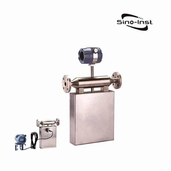
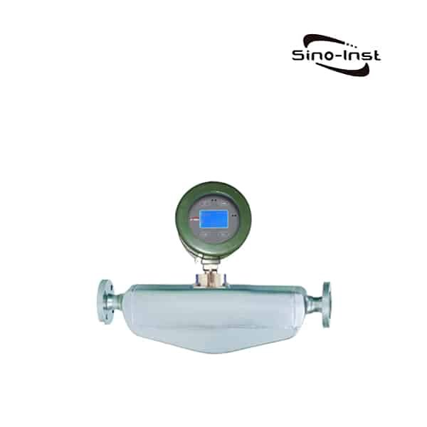
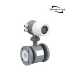
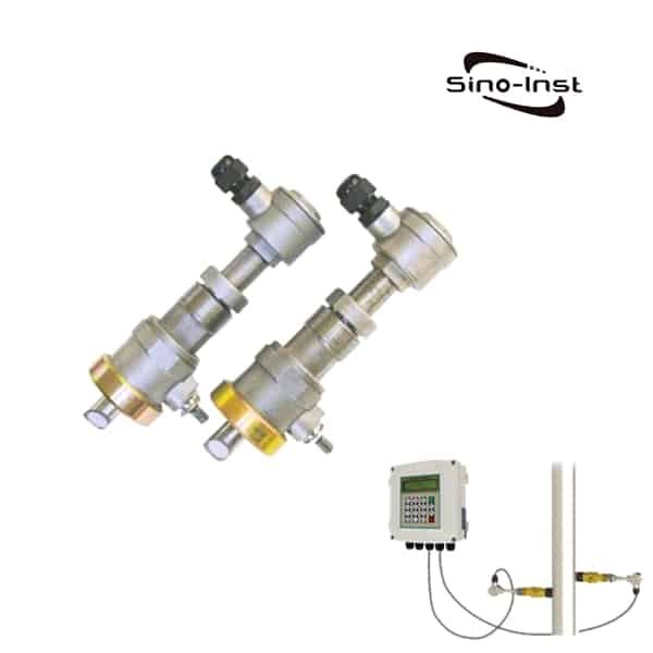
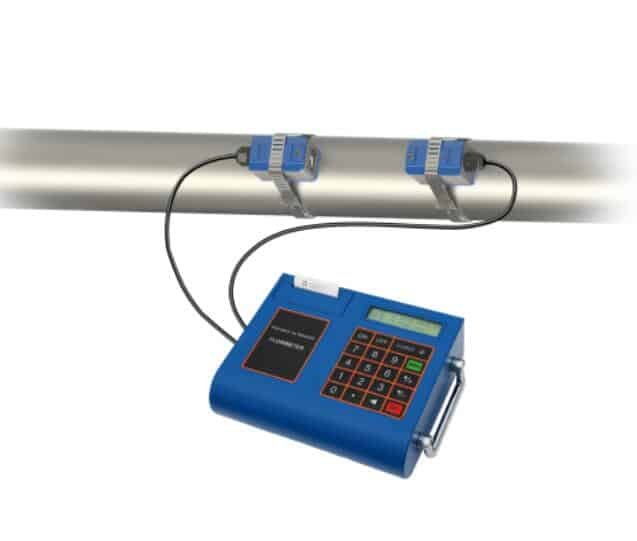
Clamp-on Ultrasonic gas flow meters, also called ultrasonic natural gas flow meters, measure liquids, and gas in industrial flow measurement applications.
Ultrasonic gas flow meters are one of the most reliable solutions,
for challenging gas flow measurement applications. (Kind like the portable ultrasonic)
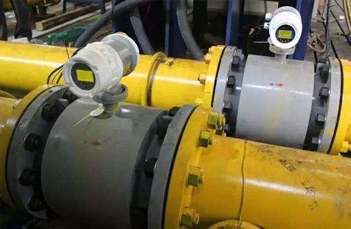
Because the sensor is clamped on to the outside of the pipe,
it is immune to the process compatibility,
concerns of an in-line flow metering technology (What is a flow meter? ).
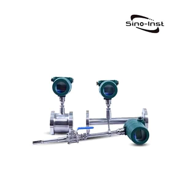
It is now possible to measure natural gas, steam, compressed air, hydrogen,
compressed air and many more using clamp-on flow meters.
Our transducer technology is also ideal for shale gas,
and coal seam gas wellhead applications.
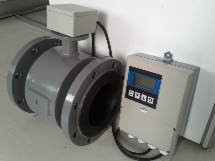
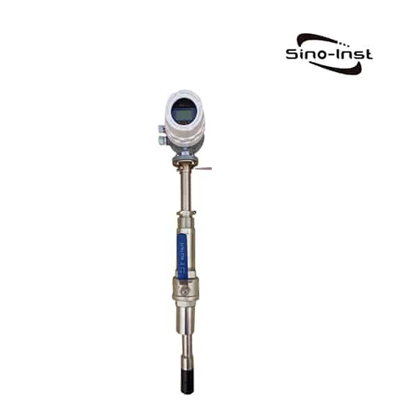
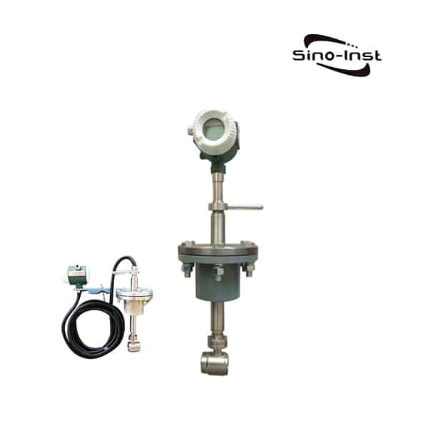
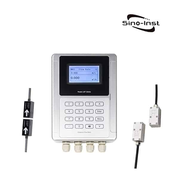
SI-3128 wall mounted ultrasonic flow meter could be applied to a variety of liquid applications,
including ultra-pure liquids, water, chemicals, raw sewage,
reclaimed water, cooling water, river water, plant effluent, alcohol, beer, etc.
What are the types of flow meter?
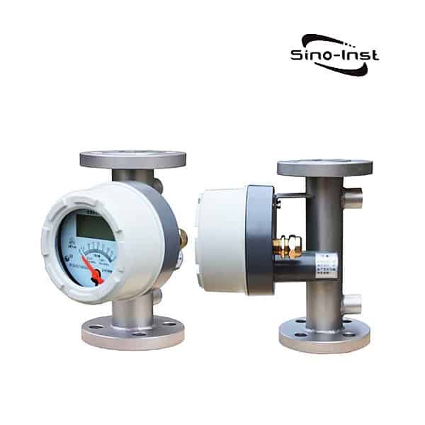
Features of Clamp-on Ultrasonic Gas Flow Meter


- Accuracy: 1%
- Ingress protection level: IP67 (transmitter), IP68 (sensor)
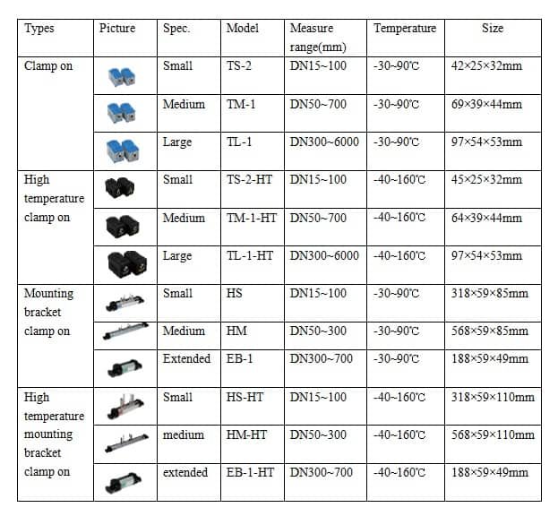
- Wide measurement range, pipe size from DN15mm to DN6000mm.
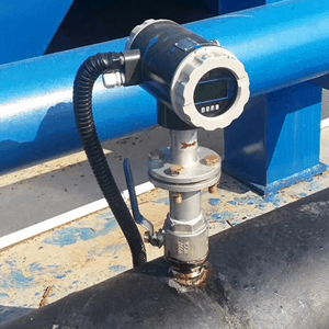
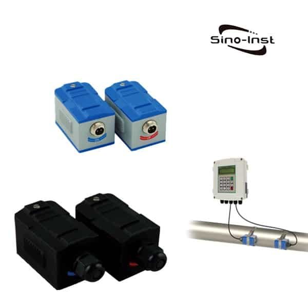
- Three installation types: wall mounting, DIN-rail mounting, explosion-proof box mounting
- Could operate with temperature sensors for heat/energy measurement.
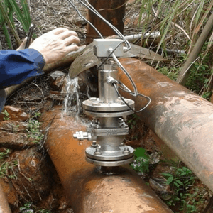
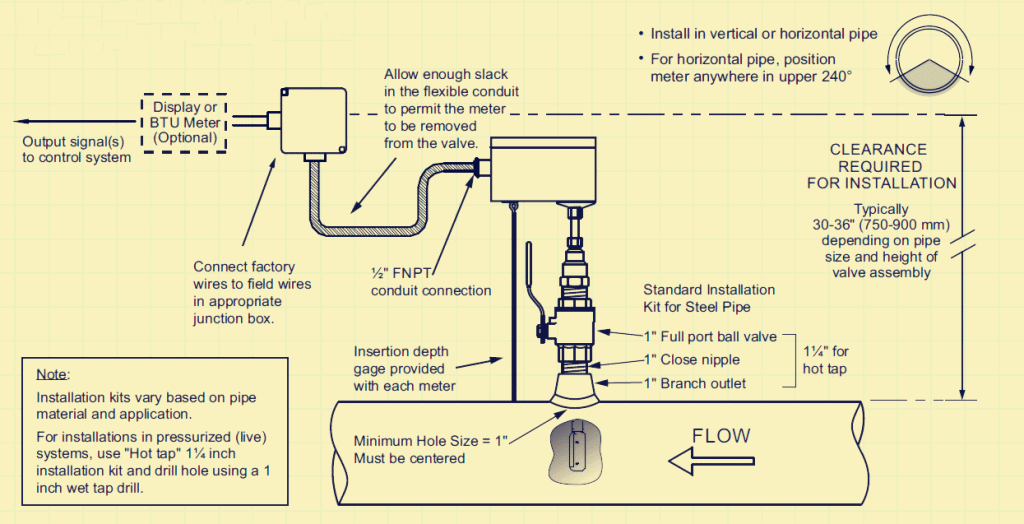
- Could be installed without shut down equipment operation
Specifications for Clamp-on Ultrasonic Gas Flow Meter
|
Items |
Performance & Parameter |
||
|
Host
|
Principle |
Transit- time ultrasonic flowmeter |
|
|
Accuracy |
±1% |
||
|
Display |
2X20 character LCD with backlight, support the language of Chinese, English and Italy |
||
|
Signal Output |
1 way 4~20mA output, electric resistance 0~ 1K, accuracy 0. 1%(optional) 1 way OCT pulse output(Pulse width 6~1000ms, default is 200ms) 1 way Relay output |
||
|
Signal Input |
3 way 4~20mA input, accuracy 0. 1%, acquisition signal such as temperature, press and liquid level |
||
|
Connect the temperature transducer Pt100, can finish the heat/energy measurement |
|||
|
Data Interface |
Insulate Rs485 serial interface, upgrade the flowmeter software by computer, support the MODBUS |
||
|
Special Cable |
Twisted-pair cable, generally, the length under 50 meters ; Select the RS485, transmission distance can over 1000m |
||
|
Pipe Installation Condition |
Pipe Material |
Steel, Stainless steel, Cast iron, Copper, Cement pipe, PVC, Aluminum, Glass steel product, liner is allowed |
|
|
Pipe Diameter |
DN32~6000mm |
||
|
Straight Pipe |
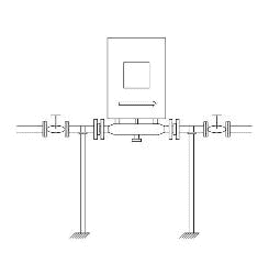
Transducer installation should be satisfied: upstream10D, downstream 5D, 30D from the pump |
||
|
Measuring Medium |
Medium |
water,sea water ,alcohol,Acid and alkali,waste water,beer,all kinds of oil Single liquid can transmit sound wave. |
|
|
Temperature |
-30~160℃ |
||
|
Turbidity |
No more than 10000ppm and less bubble |
||
|
Flowrate |
0~±7m/s,Forward and backward measurement |
||
|
Work environment |
Protection grade |
Host:IP67;flow sensor:IP68 |
|
|
temperature |
Host:-20~60℃;flow sensor:-30~ 160℃ |
||
|
Humidity |
Host: 85%RH; Flow sensor:can measure under water, water depth^2m (tansducer sealed glue) |
||
|
Power Supply |
DC8~36V or AC85~264V |
||
|
Power Consumption |
1.5W |
||
|
Dimension |
132*150*85mm(host) |
||
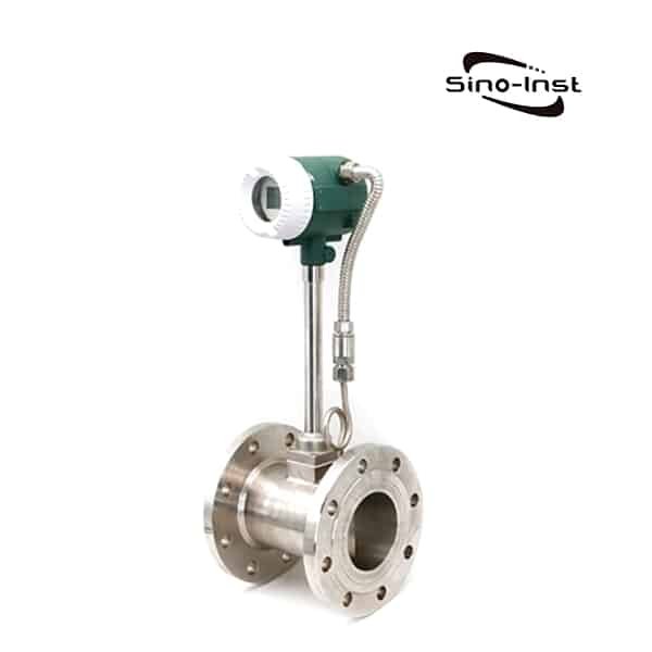
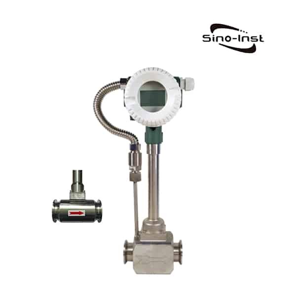
You may like: Vortex shedding flow meter
Gases that can be measured with ultrasonic clamp-on flowmeters include:
| Compressed Air | Hydrogen | Oxygen |
| Nitrogen | Steam | Natural Gas |
| Propane | Butane | Corrosive Gases |
| Erosive Gases | High Purity Gases | Sterile Gases |
| Toxic Gases | Inert Gases | Compressed Air |
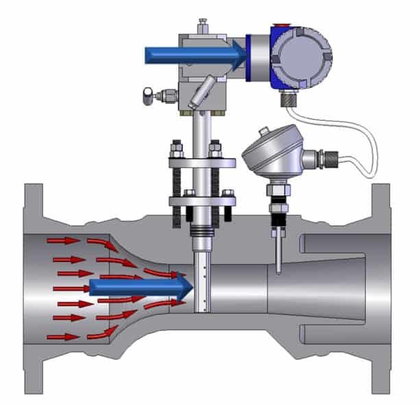
What is ultrasonic gas meter?
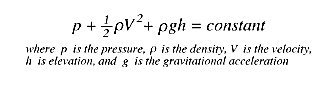
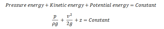
Ultrasonic flowmeters use sound waves to determine the velocity of a fluid flowing in a pipe.
At no flow conditions,
the frequencies of an ultrasonic wave transmitted into a pipe,
and its reflections from the fluid are the same.
Under flowing conditions, the frequency of the reflected wave is different due to the Doppler effect.
When the fluid moves faster, the frequency shift increases linearly.
The transmitter processes signals from the transmitted wave,
and its reflections to determine the flow rate.
Transit time ultrasonic flowmeters send and receive ultrasonic waves,
between transducers in both the upstream and downstream directions in the pipe.
At no flow conditions,
it takes the same time to travel upstream and downstream between the transducers.
Under flowing conditions, the upstream wave will travel slower and take more time than the (faster) downstream wave.
When the fluid moves faster, the difference between the upstream and downstream times increases.
The transmitter processes upstream and downstream times to determine the flow rate.
They represent about 12% of all flowmeters sold.
The ultrasonic principle can also be used to measure water depth. Please refer to Portable Ultrasonic Water Depth Gauge for water depth measurement.
You may like: Nitrogen flow meter
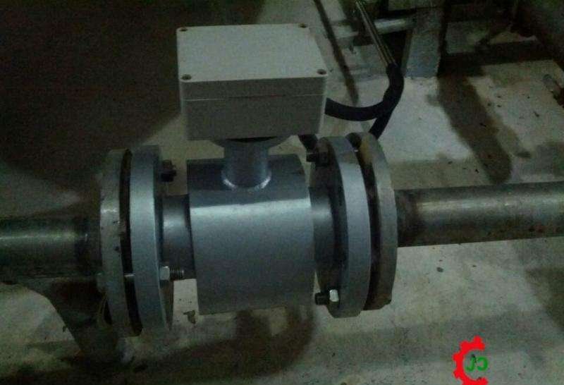
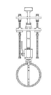
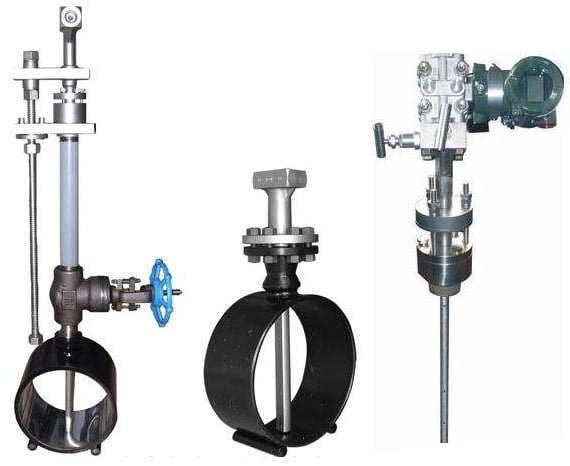
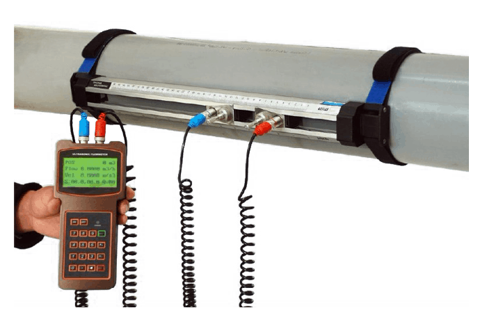
How does a clamp-on flow meter work?
A clamp-on ultrasonic gas flow meter produces signals,
that is five to ten times more powerful,
then those of traditional ultrasonic transducers.
The new clamp-on transducers produce clean, coded signals with very minimal background noise.
The result is that a clamp-on gas flow meter can now provide optimum performance,
even with low-density gas applications.
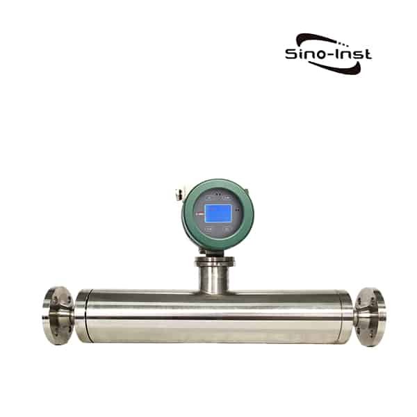
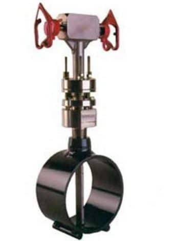
Today, our ultrasonic clamp-on gas flowmeters such as the SI-3128 can measure the flow of any gas,
and then calculate mass flow using a pressure transmitter connected to the analog input.
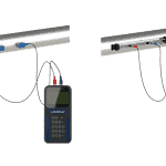
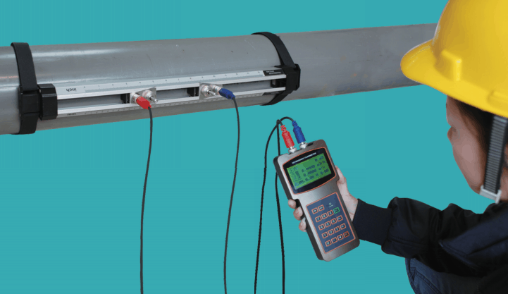
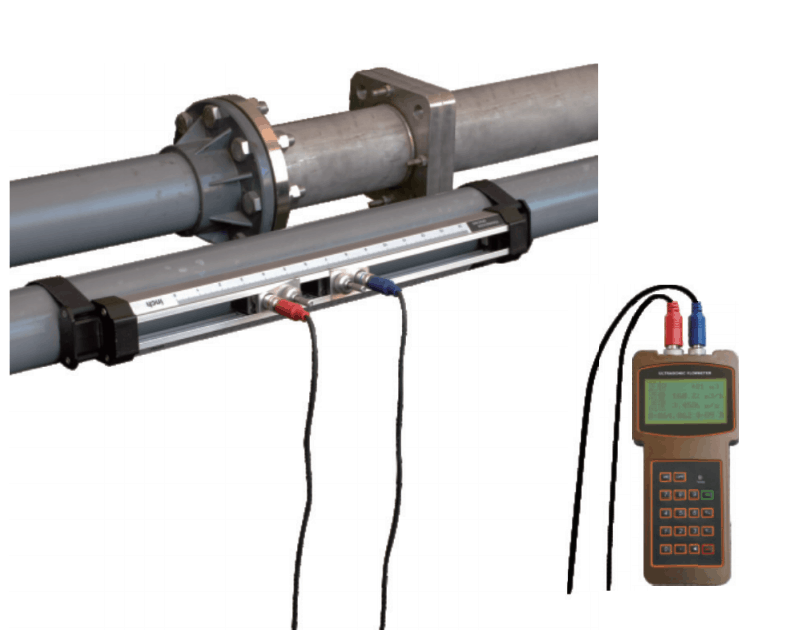
Inline ultrasonic flowmeters

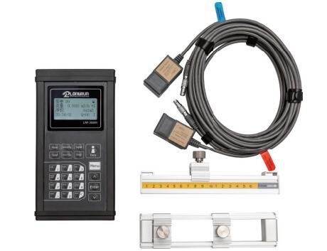
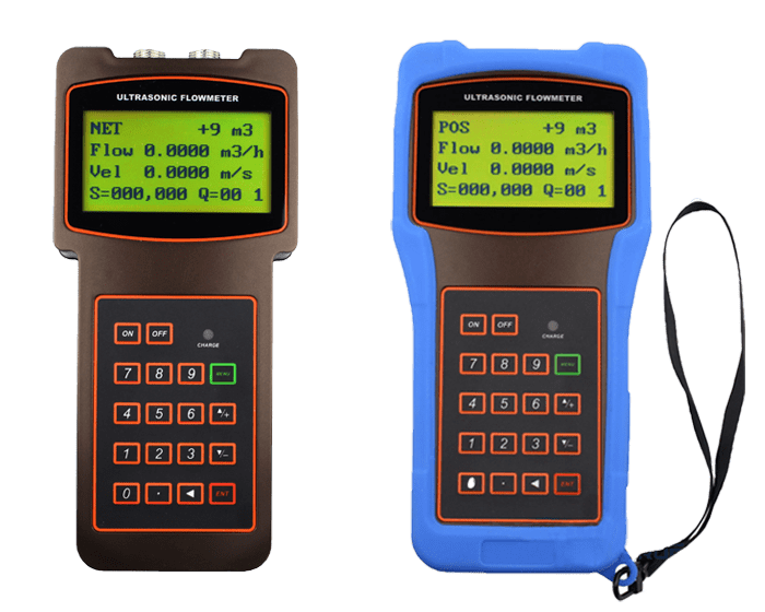
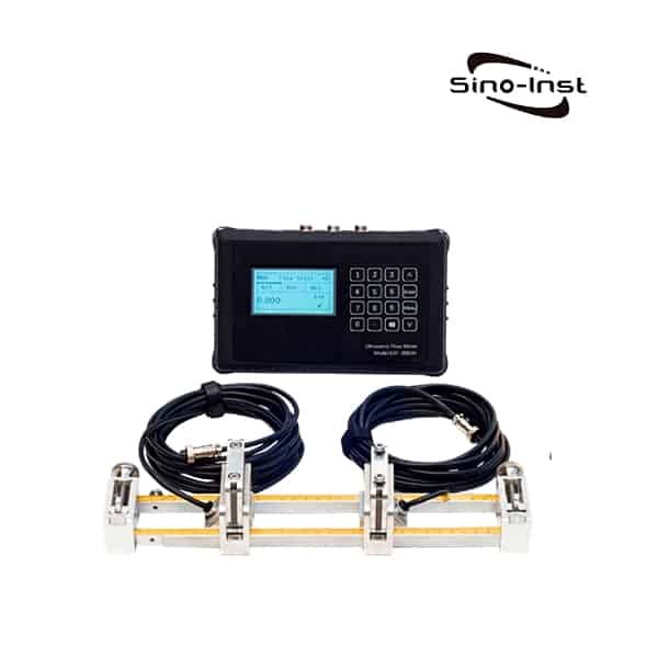
The SI-3000H Portable Ultrasonic Flowmeter is a widely used time difference ultrasonic flowmeter,
for on-line calibration and inspection of liquid flow in various industrial sites.

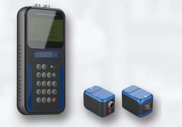
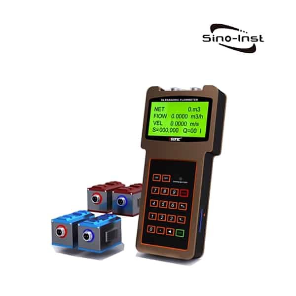
Handheld ultrasonic flow meter, also known as Portable Doppler flow meter, or Inline ultrasonic flow meter.
SI-2000H handheld ultrasonic flow meter is a representative of portable ultrasonic flow meters.
More Gas Flow Meters
Sino-Instrument offers 20 Gas flow meter products, with Best Price.
About 13% of these are Petroleum& Chemical flow meters, 4% are water treatment flow indicators.
The best Reference price is USD 2000-7000.
A wide variety of gas flow meter options are available to you, such as free samples, paid samples.
Sino-Instrument is clamp-on ultrasonic flow meter suppliers, located in China.
clamp-on ultrasonic flow meter products are most popular in North America, Mid East, and Eastern Europe.
The United States, and India, which export 99%, 1%, and 1% of ultrasonic level transmitter respectively.
You can ensure product safety by selecting from a certified supplier,
with ISO9001, ISO14001 certification.
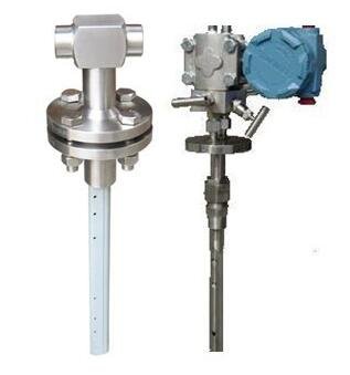
Of course, you can also choose other gas flow measurement instruments, like:
Request a Quote
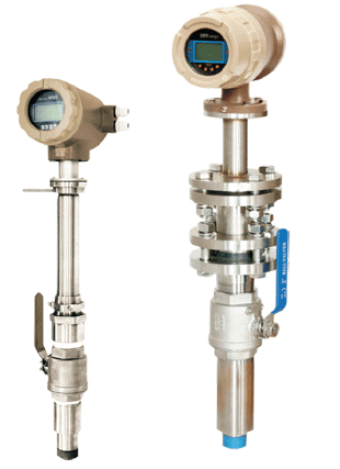
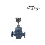
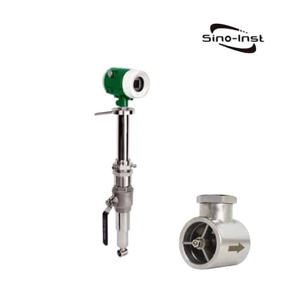
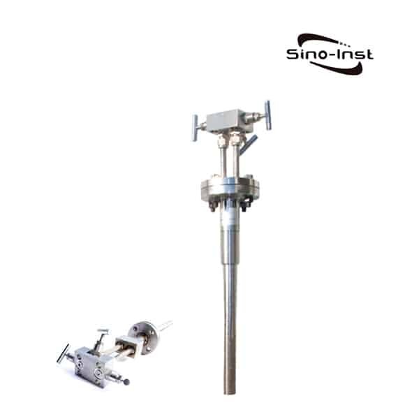
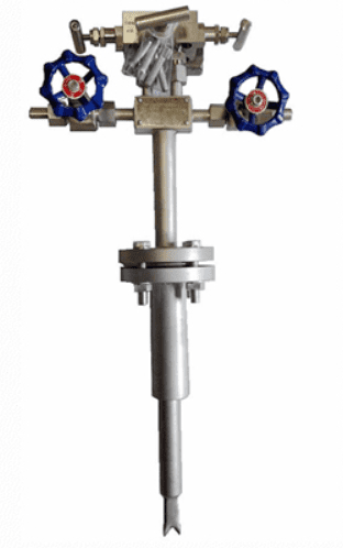
Insertion Magnetic Flow Meter SI-3121 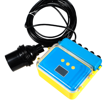
ULT-200 Ultrasonic Level Detector 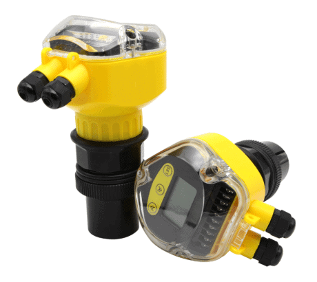
ULT-100A Ultrasonic Level Transducer 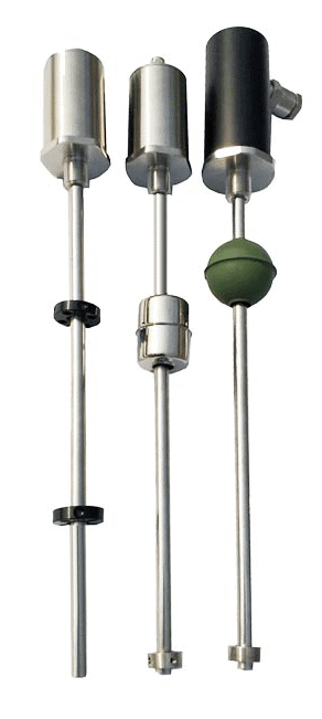
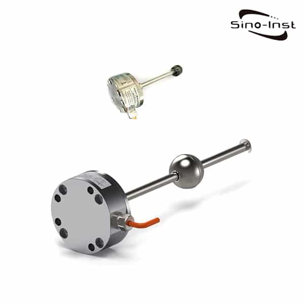
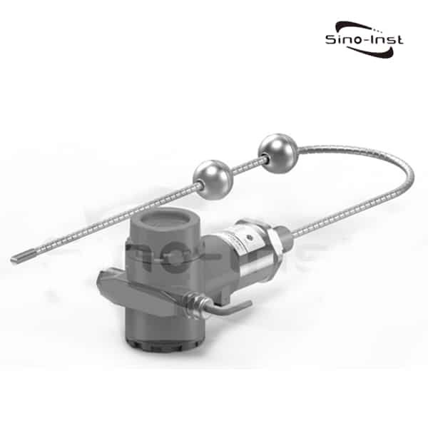
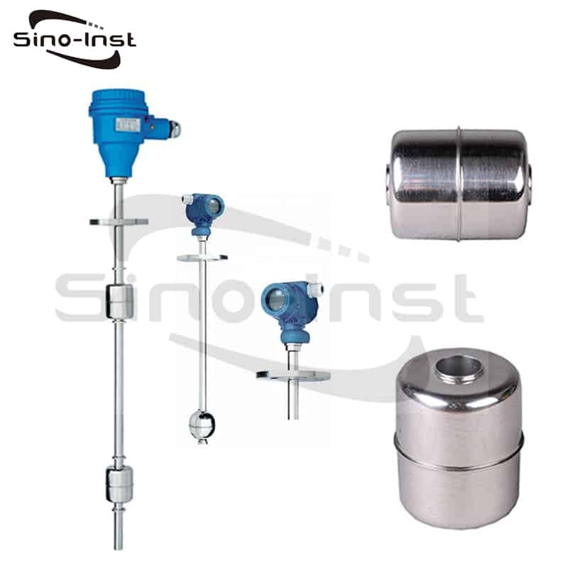
SI-100 Magnetostrictive Level Sensor 
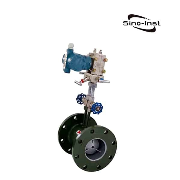
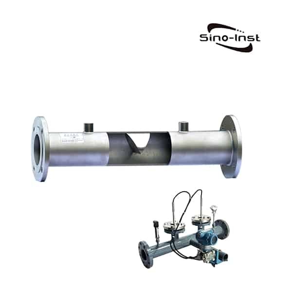
Orifice flow meter 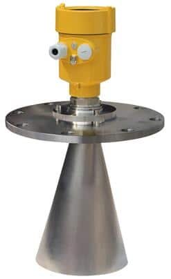
804 Radar Level Sensor 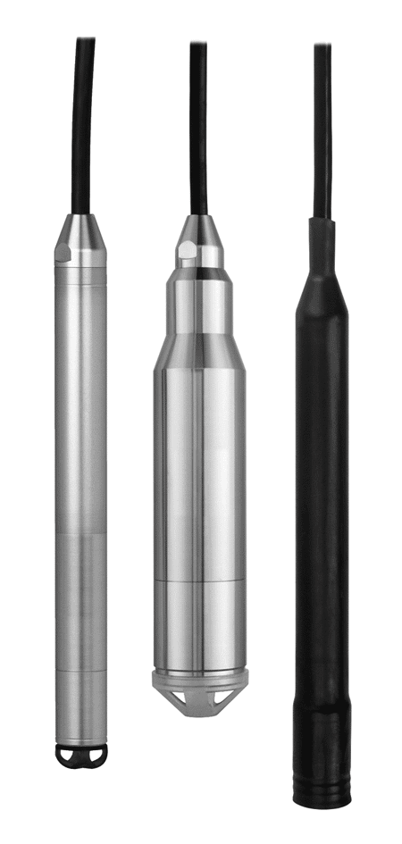
SI-151 Hydrostatic Level Sensor 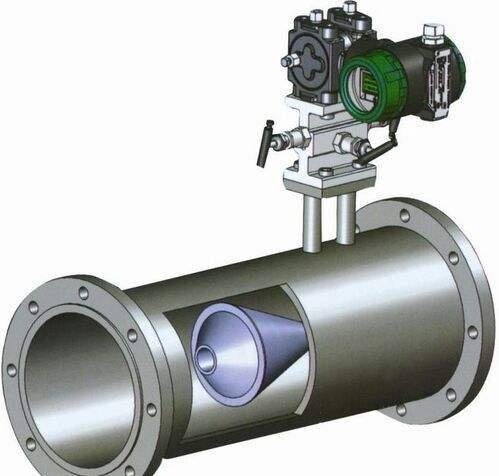
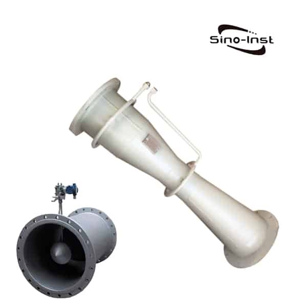
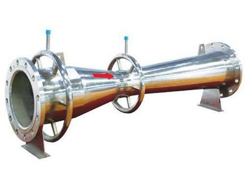
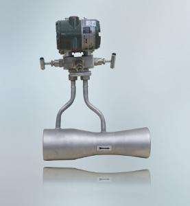
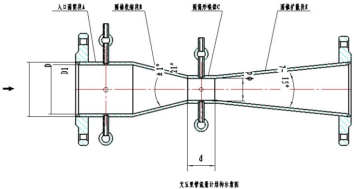
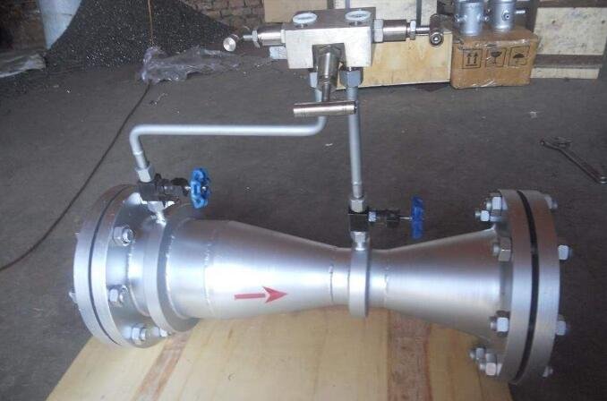
Venturi flowmeter 
3051ANB Annubar Flow Meter 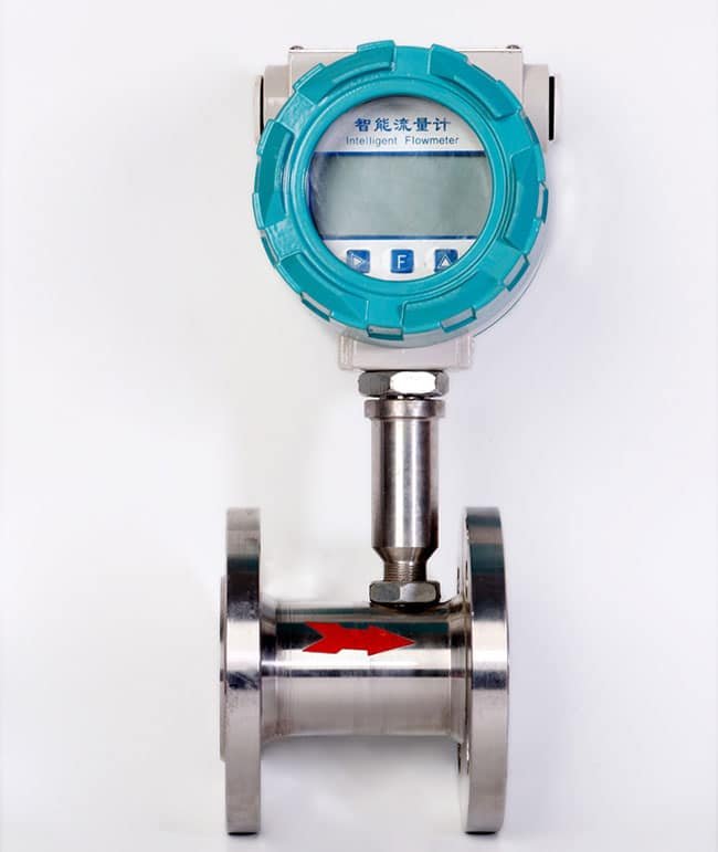
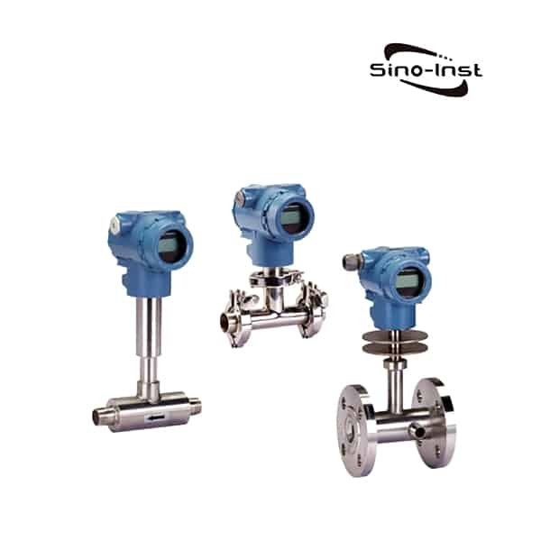
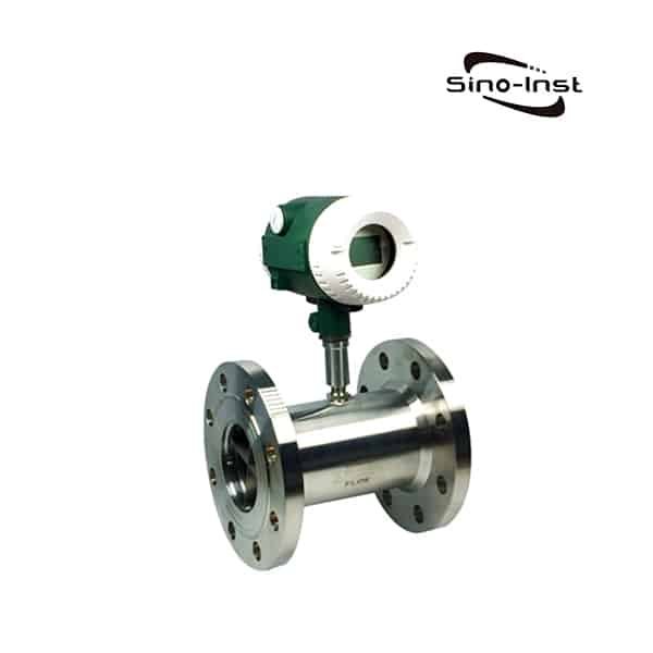
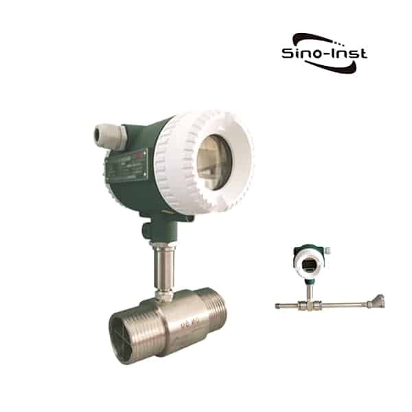
Liquid Turbine Flow Meters 
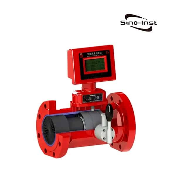
Gas Turbine Flow Meters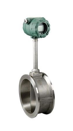
Industrial Vortex Flow Meter 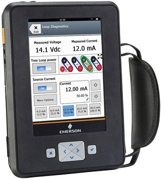
Emerson AMS Trex Device Communicator 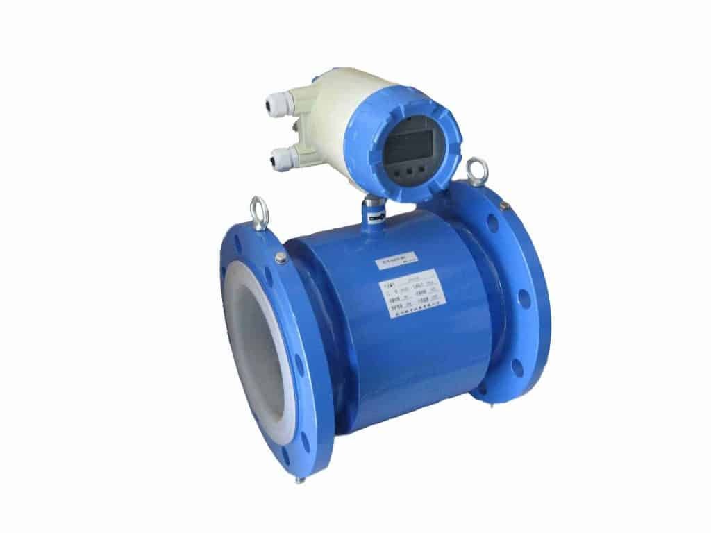
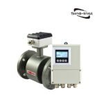
General Purpose Mag Meter 
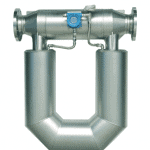
Thermal mass flowmeters 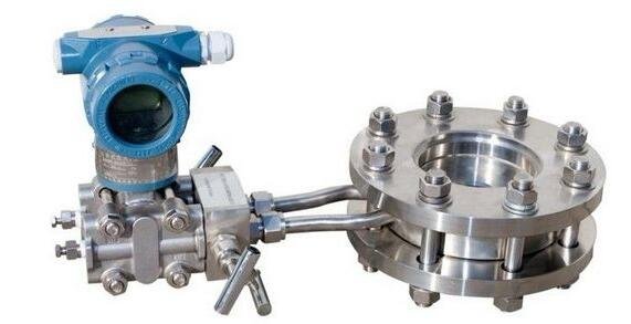
Orifice flow meter


Wu Peng, born in 1980, is a highly respected and accomplished male engineer with extensive experience in the field of automation. With over 20 years of industry experience, Wu has made significant contributions to both academia and engineering projects.
Throughout his career, Wu Peng has participated in numerous national and international engineering projects. Some of his most notable projects include the development of an intelligent control system for oil refineries, the design of a cutting-edge distributed control system for petrochemical plants, and the optimization of control algorithms for natural gas pipelines.