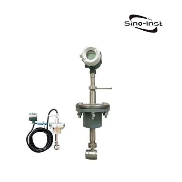
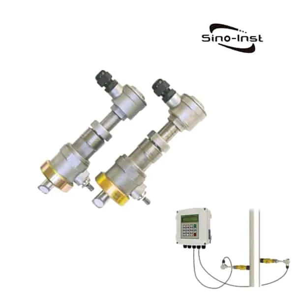
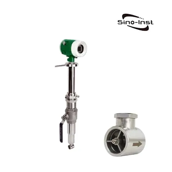
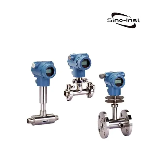
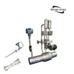
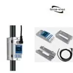
Insertion Magnetic Flow Meter, also called insertion electromagnetic flow meter, is an insertion type flow meter. Insertion magnetic flowmeter can be installed without stopping the flow. Suitable for large diameter DN300-3000.
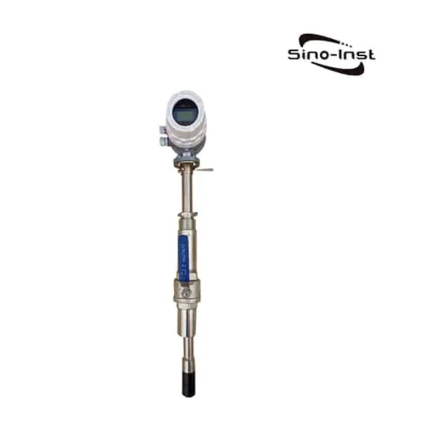
Insertion Magnetic Flow Meter adopts pressure tapping and installation technology. Insertion electromagnetic flow meter is composed of insertion electromagnetic sensor and electromagnetic flow converter.
Installation can be divided into an online installation type of the cut-off valve, and water control installation type without stop valves. The Insertion Magnetic Flow Meter is suitable for measuring the volume flow of various conductive liquids in the pipeline. It can also be used to measure corrosive conductive liquids such as acid, alkali and salt.
Sino-Inst offers a variety of Magnetic Flow Meters for flow measurement. If you have any questions, please contact our sales engineers.
Features of Insertion Magnetic Flow Meter
Compared with the pipe segment electromagnetic flowmeter, the advantages of Insertion Magnetic Flow Meter:
- No need to cut off the water, cut off the pipeline, install directly on the old pipeline;
- Easy to disassemble during maintenance;
- Especially suitable for large-diameter pipelines, with high cost performance;
- The accuracy is lower than the flange type, and it is mostly used for process control rather than measurement;
- It can be made into one-piece or component pose;
- The Insertion electromagnetic structure can be easily installed and disassembled without stopping the water under low pressure or under pressure. Therefore, it is very suitable for the fluid measurement of existing pipelines and facilitates the maintenance and repair of instruments.
- The measurement accuracy is not affected by changes in physical parameters such as the temperature, pressure, density, viscosity, conductivity (as long as the conductivity is greater than 20μs/cm) of the measured medium.
- The sensor has almost no pressure loss and extremely low energy loss.
- Large flow measurement range. The full-scale flow rate in the measured pipe can be set arbitrarily from 1m/s to 10m/s, and the output signal has a linear relationship with the flow rate.
- The flowmeter not only has 0~10mA or 4~20mA standard current output, but also 1~5kHz frequency output
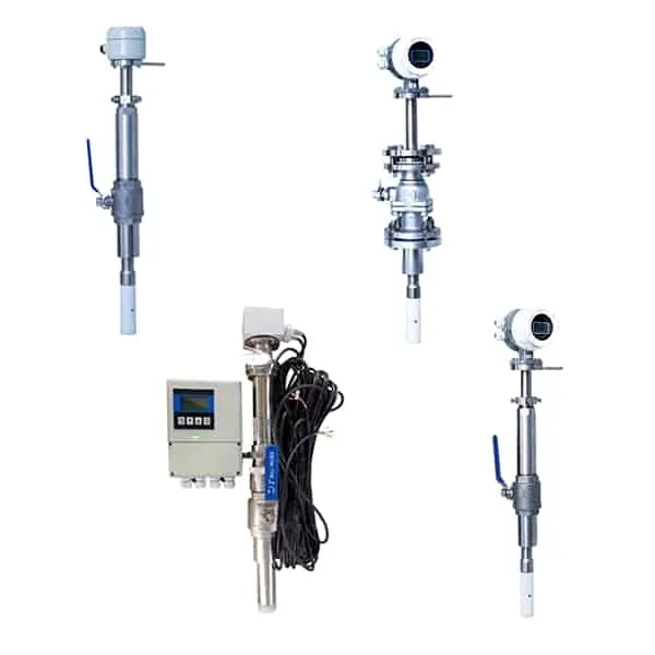
Specifications of insertion electromagnetic flowmeter
| Medium | Water, sewage water, acid, alkali, etc. | ||
| Diameter | Dn300~DN3000mm | ||
| Accuracy | ±2.5% | ||
| Temp. range | -20~+150℃ | ||
| Pressure | 1.6 MPa | ||
| Flow rate | 0.5~6m/s | ||
| Straight pipe required | Upstream≥5DN, downstream≥3DN | ||
| Electrode | 316L,Hastelloy C(HC), Titanium(Ti), Tantalum(Ta),Platinum(Pt) | ||
| Installation way | Without a ball valve or with a ball valve | ||
| Body material | Stainless steel | ||
| Power supply | 220VAC/24VDC/Lithium battery | ||
| Signal output | Pulse output, 4~20mA | ||
| Communication | RS485,Hart, GPRS etc. | ||
| Explosion-proof | No | ||
| Protection class | IP65(compact type), IP68(remote type) | ||
| Working environment | Temp. Range: -20~+60℃, humidity: 5%~90% |
Applications of Insertion Magnetic Flow Meter
- Potable Water
- Water Distribution
- Pumping Stations
- Filter Balancing and Backwash
- Reclaim Water
- Treated Water
- Irrigation Water
- Cooling Water
- Raw Water
Extended reading: 2 inch Water Flow Meter
Insertion magnetic flow meter principle
All MAG Meters operate under the same fundamental principle of classical physics (Faraday’s Law of Electromagnetic Induction):
E = CONSTANT x B x D x V
The law states that the magnitude of the voltage (E) induced in a conductive medium, moving through a magnetic field is directly proportional to the strength of the magnetic field (B), the path length between the probes (D), and the velocity of the medium (V).
In principle and implementation, it is possible to fix all parameters except velocity.
Thus a MAG Meter responds only to “velocity” and is extremely insensitive to changes in fluid conditions (density, viscosity, etc.) and application constraints (pressure, temperature, and mechanical vibrations, as well as fluid pulsation).
The operation of a MAG Meter is completely analogous to an electrical generator.
A voltage is induced in a conductor that is moving at right angles through a magnetic field.
The faster the conductor moves, the more voltage is generated.
You may want to know more about: Magnetic Flow Meters technical guide|What is &How they work?
Advantages of Magnetic Flowmeters
Electromagnetic (MAG) flowmeters have been widely used in industry for over 50 years.
And for good reason, the advantages of MAG meters are irrefutable.
- High reliability – no moving parts
- No scheduled maintenance
- Good accuracy: 0.5% to 2.0% of reading
- Very wide range: up to 100:1
- No pressure drop
- The wide selection of materials
- The wide selection of fluids metered
Extended reading: Industrial Magmeters
Typical Installation of Insertion Magnetic Flow Meter
Easy To Install
- Place saddle and ball valve
- Hot tap
- Insert meter and set the depth
- Tighten clamp
- Provide electrical Ground connection on plastic pipes

Extended Reading: Special Magnetic Flowmeter Installation situation
Choice of installation environment
- It should be installed at the lower part of the horizontal pipeline and vertically upwards, avoid installing at the highest point of the pipeline and vertically downwards;
- It should be installed on the rising part of the pipeline;
- Installation in the open discharge pipe should be installed at the lower part of the pipe;
- If the pipeline drop exceeds 5m, install an exhaust valve downstream of the sensor;
- The control valve and shut-off valve should be installed downstream of the sensor, not upstream of the sensor;
- The sensor must not be installed at the inlet and outlet of the pump, it should be installed at the outlet of the pump.
- Keep away from equipment with strong fields, such as large motors and large transformers.
- There should be no strong vibration in the installation place, and the pipeline should be firmly fixed. The ambient temperature should not change much.
- The installation environment should be easy to install and maintain.
Choice of installation location
The installation location must ensure that the pipeline is always filled with the fluid under test.
Choose a place where the fluid flow pulse is small, that is, away from the pump, valves, elbows and other local resistance parts.
When measuring two-phase (solid, liquid or gas, liquid) fluids, choose a place that is not easy to cause phase separation.
Avoid negative pressure at the measurement site.
The diameter or circumference of the side pipe is easy to measure, and the ovality should be small.
Length of straight pipe
The length of the straight pipe section on the upstream side of the sensor installation pipeline should be greater than or equal to 10D, and the downstream side should be no less than 5D (D is the diameter of the pipeline being tested).
The flow control valve should be installed on the pipe under test on the upstream side of the sensor, and the flow control valve should be installed on the downstream side of the sensor. When measuring, usually the flow control valve should be fully open.
Installation method
Vertical installation, when the sensor is inserted into the pipeline, it should be perpendicular to the central axis of the pipeline, and the included angle with the pipe section is less than 50. It is suitable for measuring clean media with small pipeline vibration.
There are two ways to insert the insertion point of the electromagnetic flow sensor. One is to insert at 1/4 of the inner diameter of the pipe. The other is to insert at 1/2 of the inner diameter of the pipe.
Correctly weld the mounting base to the pipe. Clean up welding slag and burrs on the mounting base of the pipe under test.
Turn off the upstream flow control valve or use a low-pressure water supply.
Install the DN50 ball valve on the mounting base. Note that the long cavity of the ball valve faces upwards. Check whether the ball valve can be fully opened and closed. If there is any problem, repair it. Install the compression threaded seat, compression nut and rubber sealing ring on the ball valve. Loosen the positioning screw and the compression nut, and insert the sensor through the ball valve into the pipe under test. Tighten the compression nut and the positioning screw, and at the same time, pay attention to the insertion direction of the sensor direction sign and the fluid flow direction.
Insertion depth
(1) When selecting the electrode to insert to the average flow rate, the average flow rate point is about H=0.25D from the pipe wall (D: pipe inner diameter) according to the pipeline turbulent flow conditions. Press the handle to make the insertion rod enter the pipe H deep. (L2 at this time = original L2-H)
(2) After confirming that the insertion depth is correct, turn the flow direction rod to make its connection parallel to the centerline of the pipeline. At this time, the connection between the two electrodes will be perpendicular to the centerline of the pipeline. That is, the connection between the electrodes is perpendicular to the flow rate.
(3) After adjustment, first tighten the lock nut firmly, and then tighten the three locknuts separately. One of their functions is to ensure that the insertion rod is not pushed out by the pressure in the tube. The other is to ensure that the insertion rod does not vibrate.
(4) During actual on-site installation, the insertion depth is only allowed to be 0.25D, which is a quarter of the diameter of the pipe. The insertion depth is 0.5D, which is the center of the pipe.
(5) Loosen the fastening screws under the junction box. Rotate the junction box to the position you are satisfied with and tighten the nuts.
More Featured Insertion flowmeters
At present, there are many kinds of Insertion flowmeters in use. According to the working principle of the Insertion flowmeter detection head, it can be divided into Insertion turbine, Insertion vortex, Insertion electromagnetic, Insertion ultrasonic, and Insertion target flowmeter.
The correct choice of the flowmeter is of great significance for flow measurement. Choosing different flow meters under the same working conditions will definitely have a considerable difference in the final measurement results.
If the initial selection is improper, it may even lead to the inability to perform quantitative measurements and cause damage to the instrument. Therefore, it is necessary for users to have a correct understanding of how to choose a suitable flow meter. Knowing some basic selection methods will help make mistakes when choosing meters.
In order to ensure the use of the flow meter in the production site process. The choice of flowmeter, in general, must be determined according to the medium that needs to be measured at the production site.
More Featured Wastewater Flow Meters
More about: Sewage Flow Meter Selection
Sino-Inst offers all kinds of flow meters, which can work for the wastewater.
You may like:
Exploring the Different Types of 1 Inch Flow Meters
Flow Meter Selection Guide 101: Find the Perfect Fit for Your Application
Top Industrial Heating Oil Flow Meters
Air Flow Measurement Instruments for Industrial Harsh Conditions
The Different Types of Inline Oil Flow Meters
Condensate Flow Meter-Steam Condensate Flow Meter|Types & Selection Guide
Sino-Inst offers 10 Insertion Magnetic Flow Meters. A wide variety of Industrial flow meters options are available to you. such as free samples, paid samples.
Sino-Inst is an Industrial flow Transmitter supplier, located in China. The top applying countries are China (Mainland), Hong Kong, and the United States, which supply 96%, 2%, and 1% of wireless pressure transmitters respectively.
Insertion Magnetic Flow Meter products are most popular in North America, Domestic Market, and South America. You can ensure product safety by selecting from certified suppliers, with ISO9001, and ISO14001 certification.
Request a Quote

Wu Peng, born in 1980, is a highly respected and accomplished male engineer with extensive experience in the field of automation. With over 20 years of industry experience, Wu has made significant contributions to both academia and engineering projects.
Throughout his career, Wu Peng has participated in numerous national and international engineering projects. Some of his most notable projects include the development of an intelligent control system for oil refineries, the design of a cutting-edge distributed control system for petrochemical plants, and the optimization of control algorithms for natural gas pipelines.


