After the Pressure Transducer is installed, how should I wire it? Pressure sensor wiring refers to the electrical connection of the pressure sensor. A pressure transmitter is a conversion device that converts a pressure signal into an analog signal or a digital signal. Common signals include 4-20mA, 0-10V, 0-5V and other signals. The wiring methods of these signals generally include two-wire system, three-wire system, and four-wire system.

Many beginners struggle with sensor/transmitter wiring issues. Worry that the wrong connection will cause damage to the sensor/transmitter and affect the accuracy of the measurement. This article will discuss with you the wiring of pressure sensor/transmitter. Teach you how to deal with the wiring problems of two-wire, three-wire and four-wire sensors/transmitters.
Featured Pressure Transducer for Sale
4-20mA pressure transmitter
4-20mA means that the minimum current is 4mA and the maximum current is 20mA.
The industry generally needs to measure various non-electrical physical quantities, such as temperature, pressure, speed, angle, etc. They all need to be converted into analog electrical signals before they can be transmitted to the control room or display equipment hundreds of meters away. This device that converts physical quantities into electrical signals is called a transmitter. The most widely used in the industry is to use a 4-20mA current to transmit analog quantities.
Because 4-20mA signals are least affected by electrical noise and resistance in the signal line, these sensors are best used when signals must be transmitted over long distances. These sensors are typically used in applications where the lead must be 1000 feet or more.
Extended Reading: strain gauge pressure transducer
“Instrument wire system” refers to the number of wires used for instrument power supply and standard signal transmission.
The name of the wire system is only after the birth of the two-wire transmitter.
This is the result of the widespread application of electronic amplifiers in instruments. The essence of amplification is an energy conversion process, which cannot be separated from power supply.
Therefore, the first appeared is the four-wire transmitter. That is, the two wires are responsible for the power supply. The outer two wires are responsible for outputting the converted and amplified signals (such as voltage, current, etc.).
Extended reading: Pressure Sensor Applications-Featured Industry Applications
2 wire pressure transducer wiring diagram
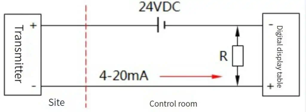
The wiring of the two-wire transmitter is shown in the figure. Power supply is 24VDC. The output signal is 4-20mA. The load resistance is typically 250Ω. The 24V supply has the lowest negative wire potential. It’s the public point.
The smart transmitter can also load the FSK keying signal of the HART protocol on the 4-20mA signal. Some digital display meters have transmission function or 24V power supply function. The function is similar to that of a two-wire transmitter.
The power supply and current signal loop of the two-wire transmitter are:
The positive terminal of the 24V power supply → the positive terminal of the transmitter → the negative terminal of the transmitter → the positive terminal of the digital display meter → the negative terminal of the digital display meter → the negative terminal of the 24V power supply, the digital display meter receives the current signal.
If a resistor R is connected in parallel with the positive and negative terminals of the digital display. The digital display meter receives the voltage signal.
Extended reading: High accuracy pressure transducers
3 wire pressure transducer wiring diagram
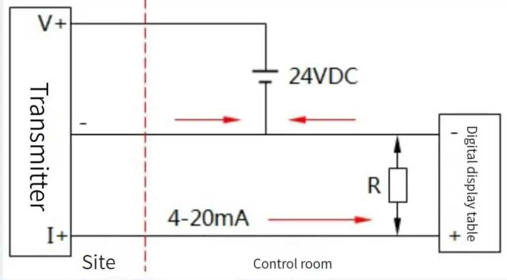
The positive terminal of the power supply of the three-wire transmitter uses one wire. Use a line for the positive end of the signal output. The negative terminal of the power supply and the negative terminal of the signal share a line. as the picture shows. The power supply is mostly 24VDC, and the output signal is mostly 4-20mA.
The power loop of the three-wire transmitter is:
24V power supply positive terminal→transmitter positive power supply wiring V+ terminal→transmitter negative terminal (common terminal)→24V power supply negative terminal.
The current signal loop is:
Transmitter’s current output I+ positive terminal → digital display meter positive terminal → digital display meter negative terminal → transmitter’s negative terminal (common terminal), the digital display meter receives the current signal.
If a resistor R is connected in parallel with the positive and negative terminals of the digital display meter, the digital display meter receives the voltage signal.
Read more about: What Is 0-10V Signal Output?
4 wire pressure transducer wiring diagram
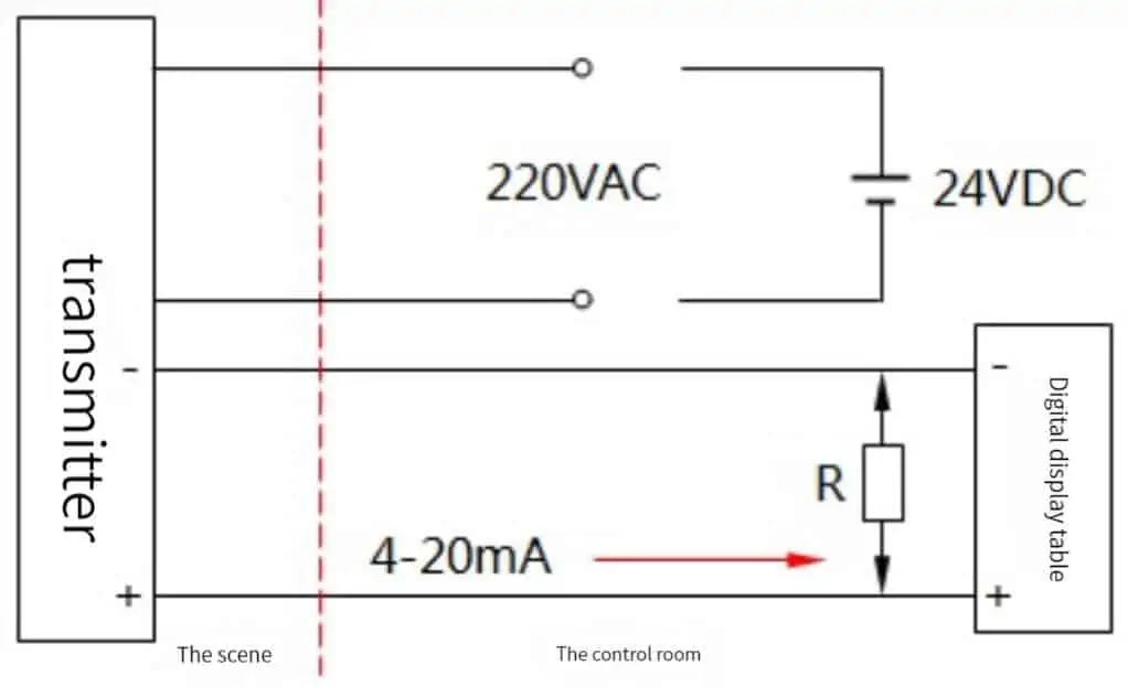
The power supply and signal of the four-wire transmitter use two wires each, and the power supply and the signal work separately. As shown in the figure, most of the power supply is 220VAC, and there are also 24VDC. The output signal is mostly 4-20mA.
The current signal loop of the four-wire transmitter is:
The current output positive end of the transmitter → the positive end of the digital display meter → the negative end of the digital display meter → the negative end of the transmitter, the digital display meter receives the current signal.
If a resistor R is connected in parallel with the positive and negative terminals of the digital display meter, the digital display meter receives the voltage signal.
Extended reading: Troubleshooting For 4-20ma Pressure Transmitter
Frequently
Asked
Questions
Pressure Transducer Wiring is actually very simple. Generally, when the pressure transmitter is used and installed, there will be an installation manual, which can be installed directly according to the manual.
Pressure transmitters include capacitive pressure transmitters and resistive pressure transmitters. A pressure transmitter is a device that converts the pressure of a gas or liquid into a usable electrical signal.
The pressure transmitter can be divided into two-wire system, three-wire system and four-wire system according to the wiring method.
The pressure transmitter has two power lines and two signal lines. The power supply is connected to 24v DC. The simple detection method is to use an ammeter or voltmeter to connect both ends of the signal line.
After the pressure transmitter power supply is connected, the ammeter will have 4ma current or the voltmeter will have 0v or 1V voltage. Read more about: What Is 0-10V Signal Output?
The current transmitter generally has 4 terminals. Two are wired. The other two do not need to be wired. The DC24V power line of the transmitter is also a 4-20mA signal feedback line.
That is to say, the AI point of your secondary meter or DAS (data acquisition system) should have a DC24V feed output.
Generally, the 4-20mA pressure transmitter is a 2-wire system, powered by 24V, and outputs a 4-20mA current signal. After the pressure transmitter arrives at the scene, many people do not know how to wire it. This is a very painful and headache.
In fact, when you open the back cover of the pressure transmitter, you will see four terminals. OUT positive and negative and TEST positive and negative. Here we take OUT positive and negative.
TEST positive and negative is the factory, the manufacturer used to calibrate the pressure transmitter. It is not necessary to control the function of the two terminals when using it on site.
Direct OUT positive and negative on the line.
Extended Reading: Fluid pressure sensor
More pressure measurement solutions
Sino-Inst is Manufacturer of Pressure Transducers. We supply more than 100 kinds of Pressure Transducers. 50% 2 Wire Pressure Transducers, 40% 4 Wire Pressure Transducers, and other types of Pressure Transducers.
Sino-Inst’s Pressure Transducers, made in China, Having good Quality, With better price. Our pressure measurement instruments are widely used in China, India, Pakistan, the US, and other countries.
The entire team at Sino-Inst’s has received excellent training, so we can ensure that every client’s needs are met. For assistance with your product requirements, whether it’s a Pressure Transducers, level sensor, or other device, give us a call.
Request a Quote

Wu Peng, born in 1980, is a highly respected and accomplished male engineer with extensive experience in the field of automation. With over 20 years of industry experience, Wu has made significant contributions to both academia and engineering projects.
Throughout his career, Wu Peng has participated in numerous national and international engineering projects. Some of his most notable projects include the development of an intelligent control system for oil refineries, the design of a cutting-edge distributed control system for petrochemical plants, and the optimization of control algorithms for natural gas pipelines.

