Updated on April 18, 2026 — The Verabar flow meter is an averaging pitot tube that measures flow by sensing differential pressure across multiple ports in a pipe cross-section. It handles pipe sizes from DN50 to DN6000, covers gas, steam, and liquid service, and delivers ±1% accuracy with far less permanent pressure loss than an orifice plate. This page covers the Verabar working principle, full specifications, and a head-to-head comparison with the Annubar.
Contents
- What Is a Verabar Averaging Pitot Tube Flow Meter?
- How Does a Verabar Flow Meter Work?
- Verabar Flow Meter Specifications
- What Is the Difference Between Verabar and Annubar?
- What Pipe Sizes and Fluids Suit a Verabar?
- FAQ
What Is a Verabar Averaging Pitot Tube Flow Meter?
A Verabar flow meter is a multi-port averaging pitot tube that measures volumetric or mass flow rate by calculating the average velocity pressure across a pipe diameter. Unlike a single-point pitot tube that samples velocity at one location, the Verabar uses four or more sensing ports distributed along the probe length to capture the actual velocity profile, including boundary layer effects near the pipe wall.
The technology was originally developed by Yokogawa (formerly Dietrich Standard) under the Verabar trade name. It belongs to the family of differential pressure flow elements but differs from orifice plates, Venturi tubes, and flow nozzles in one critical way: the Verabar is an insertion element. It slides into the pipe through a single penetration point, so installation does not require cutting the pipe or breaking flanged joints on large-diameter lines.
This insertion design makes the Verabar the preferred DP element for pipes above DN200 (8 inches). An orifice plate for a DN600 line is heavy, expensive, and causes 40–70% permanent pressure loss. A Verabar in the same line causes roughly 3–5% permanent pressure loss and costs a fraction of the orifice assembly.
How Does a Verabar Flow Meter Work?
The Verabar works by measuring the difference between total pressure (impact) and static pressure at multiple points across the pipe diameter, then averaging those readings into a single DP signal.
Multi-Port Averaging Principle
The probe body has two internal chambers. The upstream face contains multiple impact ports (typically 4–8 depending on pipe size) that sense total pressure — the sum of static pressure and velocity pressure. The downstream face has low-pressure ports that sense static pressure plus a slight negative pressure from wake effects.
Each impact port is positioned at a specific distance from the pipe center according to the equal-area method (Chebyshev spacing). This ensures that each port represents an annular ring of equal cross-sectional area, so the arithmetic average of all port readings equals the true mean velocity across the full pipe section.
DP Signal and Flow Calculation
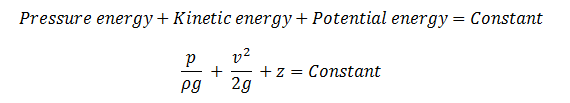
The averaged high pressure and averaged low pressure are routed to a differential pressure transmitter. The transmitter outputs a DP signal that relates to velocity by the Bernoulli equation:
V = K × √(2 × ΔP / ρ)
Where V is velocity (m/s), K is the flow coefficient (determined by probe geometry), ΔP is the measured differential pressure (Pa), and ρ is the fluid density (kg/m³). Volumetric flow rate Q then equals V × A, where A is the pipe cross-sectional area.
The Verabar’s bullet-nose profile generates a stronger DP signal than round or diamond-shaped averaging pitot tubes. Typical DP output runs 2–5 times higher than a standard round pitot probe at the same velocity, which improves the signal-to-noise ratio and extends the usable turndown range.
For applications where flow rate needs to be expressed in gallons per minute rather than standard volumetric units, see flow meters with GPM units.
Verabar Flow Meter Specifications
The table below lists the standard specification range for Verabar averaging pitot tube flow meters. Actual limits depend on the specific model variant (insertion vs flanged) and process conditions.
| Parameter | Specification |
|---|---|
| Pipe Size Range | DN50–DN6000 (2″–240″) |
| Accuracy | ±1.0% of reading (typical); ±0.5% with in-situ calibration |
| Repeatability | ±0.1% of reading |
| Turndown Ratio | 10:1 (standard); up to 15:1 with high-sensitivity DP transmitter |
| Max Operating Pressure | 40 MPa (ANSI 2500 class) |
| Temperature Range | −40°C to +450°C (standard); up to +650°C with ceramic-coated probe |
| Probe Material | 316L SS (standard), Hastelloy C-276, Monel, Duplex 2205 |
| Process Connection | Insertion (compression fitting), flanged (ANSI 150–2500) |
| Output Signal | 4–20 mA with HART (via DP transmitter); optional Modbus, FOUNDATION Fieldbus |
| Permanent Pressure Loss | 3–5% of measured DP (vs 40–70% for orifice plate) |
| Straight Pipe Requirement | 8D upstream / 4D downstream (minimum); 15D/7D recommended |
The straight pipe requirements above are general guidelines. Actual upstream/downstream distances depend on the type of disturbance (elbow, tee, valve). For detailed spacing rules by fitting type, refer to the upstream and downstream straight pipe reference.
What Is the Difference Between Verabar and Annubar?
The Verabar (Yokogawa) and Annubar (Emerson/Rosemount) are both averaging pitot tube flow meters, but they differ in probe profile shape, signal strength, and clog resistance. The table below compares the two on the parameters that matter most for selection.
| Feature | Verabar | Annubar (485) |
|---|---|---|
| Probe Profile | Bullet-nose (rounded leading edge) | T-shaped (flat leading edge) |
| DP Signal Strength | Higher — rounded profile creates stronger wake separation | Moderate — T-shape produces lower DP at same velocity |
| Accuracy | ±1.0% of reading | ±0.75% of reading (Annubar 485 with calibration) |
| Repeatability | ±0.1% | ±0.1% |
| Clog Resistance | Good — bullet nose sheds debris; self-cleaning in moderate-particle flows | Moderate — T-shape can collect buildup on leading face |
| Permanent Pressure Loss | 3–5% of DP | 4–8% of DP |
| Max Temperature | +450°C (std); +650°C (special) | +450°C (std); +600°C (special) |
| Max Pressure | ANSI 2500 (40 MPa) | ANSI 2500 (40 MPa) |
| Pipe Size Range | DN50–DN6000 | DN25–DN2400 |
| Typical Cost (DN300) | $800–$1,500 | $1,200–$2,500 |
| OEM / Manufacturer | Yokogawa (Dietrich Standard) | Emerson (Rosemount) |
When to Choose Verabar Over Annubar
Choose the Verabar when you need coverage for very large pipes (above DN2400), when the process fluid carries light particulates (the bullet nose is less prone to fouling), or when the project budget is tight. The Verabar also generates a stronger DP signal at low velocities, which helps in turndown-sensitive applications like natural gas distribution lines.
Choose the Annubar when the application requires traceable ±0.75% accuracy without in-situ calibration, when you already have a Rosemount DP transmitter infrastructure, or when the pipe is below DN50 (the Annubar goes down to DN25).
Both options produce far less permanent pressure loss than orifice plates or flow nozzles. For a broader comparison of DP flow elements including Venturi tubes, see the flow element selection guide.
What Pipe Sizes and Fluids Suit a Verabar?
The Verabar averaging pitot tube covers DN50 to DN6000 (2″ to 240″), making it one of the widest pipe-size ranges among all flow meter types. Its sweet spot is DN200 and above, where competing technologies become impractical or prohibitively expensive.
Gas Applications
Natural gas, compressed air, nitrogen, flue gas, and biogas. The Verabar’s strong DP signal works well with gases because gas DP readings are inherently small. Typical gas velocities range from 3 m/s to 60 m/s. For custody transfer, pair with a multivariable DP transmitter that compensates for pressure and temperature in real time.
Steam Applications
Saturated steam and superheated steam up to +450°C (or +650°C with special probes). The insertion mounting style is a major advantage for steam service — hot-tapping the probe into a live steam line takes less than an hour, with no shutdown required. Steam velocities from 5 m/s to 80 m/s are within the standard operating range.
Liquid Applications
Water, condensate, light hydrocarbons, and chemical solutions. For dirty liquids with suspended solids, select a probe with purge ports that allow periodic cleaning without removal. The Verabar is not recommended for high-viscosity fluids (above 30 cP) because low Reynolds numbers distort the velocity profile and degrade accuracy.
Sizing Consideration for Large Pipes
For pipes above DN1000 (40″), the probe length exceeds 1 meter. At this length, structural vibration from vortex shedding can become a concern. Verify that the probe’s natural frequency is at least 3× the expected vortex shedding frequency at maximum velocity. Most manufacturers provide vibration analysis as part of the sizing calculation for DN1000+ applications.
Featured DP & Averaging Pitot Flow Meters
Sino-Inst manufactures averaging pitot tube flow meters equivalent to the Verabar design, along with companion DP transmitters and alternative flow elements for pipes below DN50.


Averaging Pitot Tube (Verabar-Style)
Verabar averaging pitot tube for DN50-DN6000 gas, steam and liquid lines. Just 3-5% permanent pressure loss vs 40-70% for orifice plates — huge energy savings on large pipes.


Smart DP Transmitter SI-3051
SMT3151DP smart DP transmitter with German MEMS monocrystalline silicon sensor. HART and RS485 Modbus RTU protocols, 0.075% accuracy — the go-to for flow, level and density loops.

Orifice Plate Flow Meter
SI-LG orifice plate flow meter — the standard DP primary element for steam, gas and clean liquids. Supports concentric, segmental and eccentric plates, pairs with any smart DP transmitter.
FAQ
What is a Verabar flow meter?
A Verabar flow meter is an averaging pitot tube that measures flow by sensing differential pressure at multiple points across a pipe diameter. It was developed by Yokogawa (originally Dietrich Standard) and uses a bullet-nose probe profile to generate a strong, stable DP signal. It covers pipe sizes from DN50 to DN6000 and works with gas, steam, and liquid.
How accurate is a Verabar flow meter?
Standard accuracy is ±1.0% of reading with factory calibration. With in-situ calibration against a reference meter, accuracy can reach ±0.5% of reading. Repeatability is ±0.1%. These figures hold across the 10:1 turndown range; accuracy degrades below 10% of full-scale flow.
Can a Verabar be installed without shutting down the line?
Yes. The insertion-type Verabar supports hot-tap installation, where a valve and fitting assembly allow the probe to be inserted into a pressurized, flowing pipe. This is one of its major advantages for retrofit applications in steam, gas, and water systems where shutdown is costly or not allowed.
What maintenance does a Verabar need?
Routine maintenance involves checking the impulse tubing for condensate (gas/steam service) or air (liquid service) and verifying the DP transmitter zero. In dirty service, periodic purging or rod-out of the sensing ports prevents buildup. The probe has no moving parts, so mechanical wear is not a factor. Typical inspection interval is 12–24 months depending on fluid cleanliness.
How does a Verabar compare to an orifice plate?
The Verabar causes 3–5% permanent pressure loss versus 40–70% for an orifice plate. It is cheaper and faster to install on large pipes (DN200+) because it does not require flanged pipe modification. However, the orifice plate has a longer track record in custody-transfer applications and is backed by more extensive standards (ISO 5167). For pipes below DN100, an orifice plate is often more practical and equally affordable.
Get a Verabar Flow Meter Quote
Sino-Inst supplies Verabar averaging pitot tube flow meters in insertion and flanged configurations, with optional integrated DP transmitters. We provide sizing calculations, material selection support, and hot-tap installation guidance for pipes up to DN6000. Tell us your pipe size, fluid, and operating conditions — we will send you a spec sheet and delivered price within 24 hours.
Request a Quote
Verabar is a registered trademark of Yokogawa Electric Corporation. Annubar is a registered trademark of Emerson Electric Co. Product names are used for reference purposes only. Sino-Inst is an independent supplier and is not affiliated with Yokogawa or Emerson.


Wu Peng, born in 1980, is a highly respected and accomplished male engineer with extensive experience in the field of automation. With over 20 years of industry experience, Wu has made significant contributions to both academia and engineering projects.
Throughout his career, Wu Peng has participated in numerous national and international engineering projects. Some of his most notable projects include the development of an intelligent control system for oil refineries, the design of a cutting-edge distributed control system for petrochemical plants, and the optimization of control algorithms for natural gas pipelines.