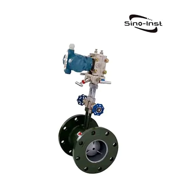
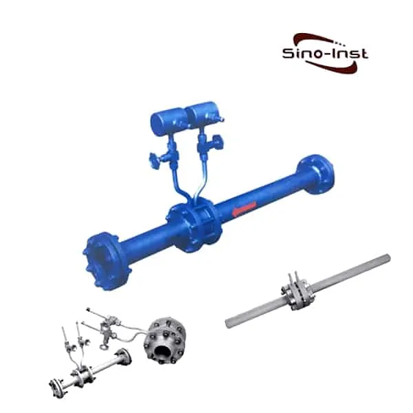
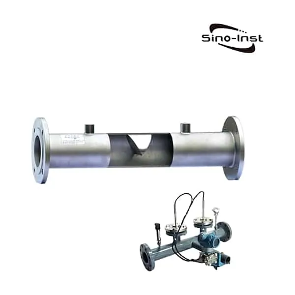
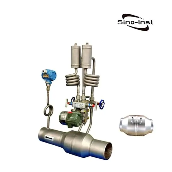
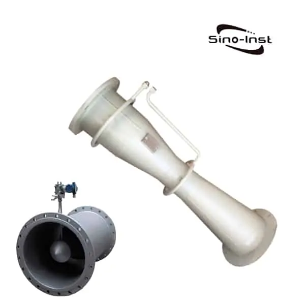
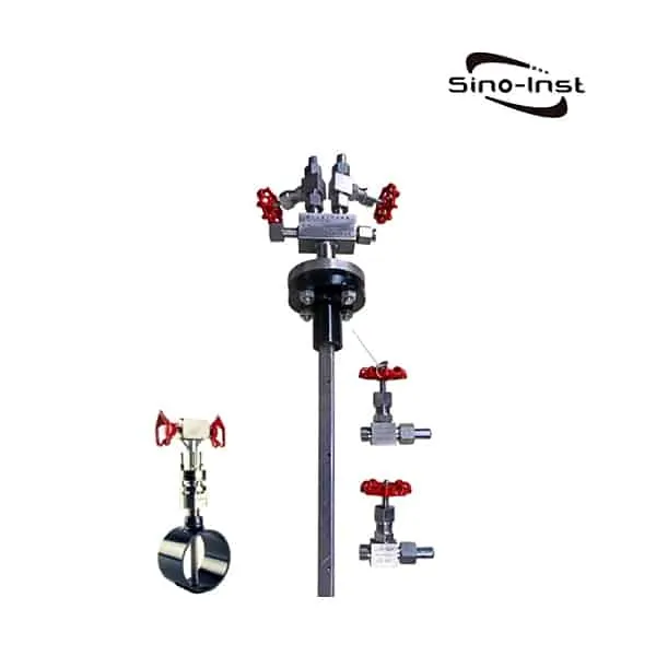
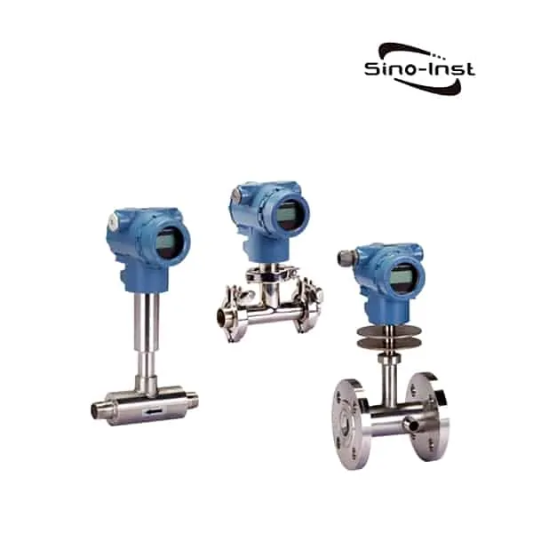
V-cone flow meter is also known as cone-type flow meter; inner cone flow meter; integrated V-cone flow meter. The principle of V-cone flow meter is the same as other DP flow meters, and it is also a throttling DP flowmeter.;
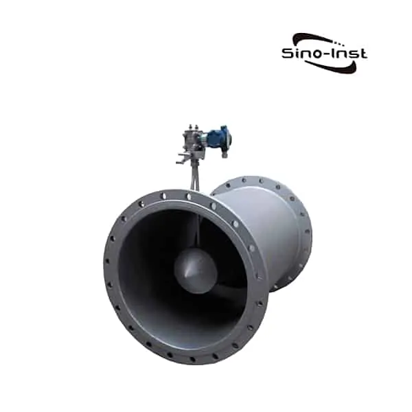
The basic principle of the V-cone flow meter is the same as that of other types of differential pressure flowmeters. They are based on the principle of energy conservation in the sealed pipeline. The V-cone flow meter is a cone-shaped shutoff piece suspended in the center of the pipeline, and the cone-shaped piece hinders the flow of the medium. Reshape the flow rate curve. Measuring media include water, steam, air, natural gas, nitrogen, coke oven gas, etc. The maximum working temperature is 450℃, and the maximum pressure is 40Mpa.
Sino-Inst, Manufacturer for differential pressure flow meters. Including the Orifice plate, Venturi, Annubar, etc. Suitable for liquid, gas, and steam flow measurement. Please contact our sales engineers for technical support!
Features of V-Cone Flow Meter
V-Cone Flow Meter Specification
| Long-term stability: | ± 0.1% F.S / Y |
| Output: | 4~20mA |
| Repeatability: | ± 0.1% |
| Minimum flow velocity: | 0.1m |
| Turndown ratio: | Normally15:1; max50:1 |
| Reynolds number range: | 8 × 10³ ~ 5 × 10⁶ |
| Operating pressure: | ≤ 16MPa, 42MPa(maximum) |
| Operating temperature: | -160 °C ~ 700 °C |
| Nominal diameter: | φ15~φ2000 (1/2″~120″) |
| Environment temperature: | ≤ 80 °C |
Extended reading: Integral DP Flow Meter|Gas, liquid, steam|Compact structure
V-Cone Flow Meter Applications
V-Cone Flow Meter can successfully measure fluids:
- Gas:
Gas: coke oven gas, blast furnace gas, city gas;
Natural gas: includes natural gas with a moisture content of more than 5%;
Various hydrocarbon gases: alkanes, olefins and other gases;
Various gas production: hydrogen, helium, argon, oxygen, nitrogen, etc.;
Corrosive gas: wet chloride gas, etc.;
Air: including air containing water, dust, compressed air, etc.;
Flue gas: flue gas discharged from various boilers and heating furnaces; - Steam: saturated steam, superheated steam;
- Liquid
Oils: crude oil, fuel oil, water-containing emulsified oil, diesel, hydraulic oil, etc.;
Water: raw water, drinking water, production water, sewage, etc.;
Various aqueous solutions: acid, alkali, saline solution, etc.;
Organic chemicals: methanol, ethylene glycol, xylene, etc.; - Special fluid
Oil + HC gas + sand;
Aerated water: H2O+N2+air; H2O+CO2, etc.;
Extended reading: Flow Measurement of Nitrogen
veris flow measurement group
Armstrong International’s Veris – Flow Measurement solutions provide outstanding flow measurement technology to meet the critical needs for your environment. Their Verabar and Accelabar patented solutions deliver consistent, accurate and reliable flow measurement to handle a wide variety of liquids, gases and steam.
V-Cone Flow Meter Working Principle
The V-cone flow meter is a differential pressure flow meter. The flow meter designed on the principle of differential pressure has been applied for more than 100 years.
The principle of differential pressure is based on the principle of energy conversion in a sealed pipeline. That is to say, for a stable fluid, the flow rate is proportional to the square root of the flow rate of the medium in the pipeline.
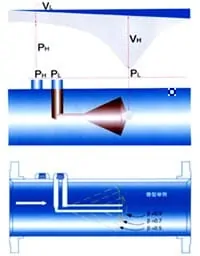
When the medium is close to the cone, its pressure is P1. When the medium passes through the intercepting area of the cone, the speed increases and the pressure decreases to P2. Both P1 and P2 are led to the differential pressure transmission through the tapping port of the cone flowmeter When the flow rate changes, the differential pressure between the two pressure taps of the cone flowmeter will increase or decrease.
The calculation formula used by the V-cone flow meter for flow calculation is the same as other differential pressure flow meters. However, the unique design of its intercepting element forces the medium in the center of the pipeline to flow around the cone. Compared with other differential pressure flowmeters. There are many advantages.
We can understand the performance of the cone flowmeter with the help of the ideal flow rate curve distribution. The fluid in the pipeline is not disturbed or hindered, which is what we call the ideal flow state. Its flow velocity is evenly distributed, and the flow velocity near the pipe wall is almost zero.
The flow velocity in the center of the pipe reaches the maximum. The flow velocity near the pipe wall is almost equal to Zero. It is caused by the friction of the pipe wall against the medium. Because the cone is suspended in the center of the pipeline, it is directly in contact with the high-speed area of the fluid, forcing the fluid in the high-speed area to mix with the fluid in the low-velocity area near the pipe wall to make the flow rate uniform.
Therefore, even if the flow rate is very low, the cone flowmeter can still make the fluid and the highest flow rate in the center of the pipe continuously interact to produce the correct differential pressure.
V-Cone Flow Meter Calculation
The simplified formula is:


Where:
QV-fluid volume flow m³/h
Cd-outflow coefficient
βV—Equivalent diameter ratio
dV—is the maximum diameter of the cone, D is the inner diameter of the pipe
ρ—Density under fluid conditions
ε-gas expansion coefficient
In reality, it is difficult to distribute the flow rate uniformly, and any changes in the pipeline may affect the fluid. Such as: bay head, valve, reducing diameter, expanding diameter, pump, tee, etc. The cone flowmeter uses a cone to reshape the upstream flow velocity distribution curve. Even in extremely harsh conditions, measurement accuracy can still be guaranteed.
Extended reading: [Working principle&Price]SI3051ANB Annubar Flow Meter
V-Cone Flow Meter Installation
1.Pipeline flange type:
Refers to the installation flange at both ends of the flowmeter. It is connected with the installation flange (also called user flange) of the same specification at both ends of the process pipeline. It is a more commonly used structure.
The applicable caliber (DN50mm~3000mm). This form is suitable for split installation of throttling device and differential pressure transmitter. It is generally used when measuring steam flow. It can also be used when measuring other high-temperature media.
2.Flange clamping type:
Used for the installation of small-mouth flow meters. Only 2 flanges are required for each flowmeter process pipeline. The flange and the process pipeline are welded together. Then clamp the flowmeter between the two flanges. The installation method here is the same as that of the vortex flowmeter (≤300mm).
3.Small-caliber integrated type:
Suitable for fluids with a diameter of ≤DN40mm and a medium temperature of ≤120℃. The structure is to directly combine the differential pressure transmitter with the tower flow meter into a whole.
There is no pressure guiding tube, pressure taking valve, three valve group between the two. Make the installation very simple (the same as the vortex flowmeter installation method). When the differential pressure transmitter adjusts the zero point, the valve of the process pipeline needs to be closed, and then the zero can be adjusted.
Note: This installation method cannot be used to measure high-temperature media. It is because the high-temperature media will enter the measuring room of the differential pressure transmitter and damage the measuring diaphragm of the transmitter.
4.Pipeline butt welding type:
Refers to the tower flowmeter and the process pipeline cannot be connected by flange (the flowmeter body cannot be flanged). The flowmeter and the process pipeline are directly welded together during installation. The cost of this structure is relatively low (the cost of 4 flanges is reduced), and it is a one-time installation. Generally used in larger diameter occasions.
5.Conventional fluid integration type:
Refers to the fluid whose medium temperature is ≤120℃. Applicable pipe diameter: DN50~DN3000. According to different fluids and user requirements, the manufacturer welds (or assembles) valves and three-valve groups on the flowmeter before leaving the factory. The user can assemble the flowmeter and transmitter together when installing on site.
6.Steam integrated type:
It means to assemble the transmitter and the tower flowmeter together when measuring the steam flow. Between the transmitter and the flowmeter, we must assemble the “three-valve group dedicated for steam” of our company. So cancel The pressure guiding tube is greatly simplified and the pressure taking structure is greatly simplified.
7.Liquid antifreeze type:
Refers to the “liquid special isolation tank” installed by our company between the tower flowmeter and the transmitter. The tank contains a special medium, which can not freeze at a lower temperature. This installation method is used when measuring liquids, especially when the outdoor environment is relatively low. The liquid in the measuring chamber of the transmitter is easy to freeze and damage the transmitter.
8.Square pipe flange type:
Refers to the process pipe is a square pipe. The flow meter measuring pipe is a round pipe. The two are connected by a special “square-circle” connector.
Frequently
Asked
Questions
Related DP Flow Meters
Related Blogs
Sino-Inst offers over 10 V-cone flow meter products. These are differential pressure flow meters, 40% are water meters (like the Insertion Turbine Flow Meter), and 40% are water treatment (like the Annubar flow meter ).
A wide variety of V-cone flow meter options are available to you, such as free samples, paid samples.
Sino-Inst is a globally recognized supplier and manufacturer of V-cone flow meter, located in China. The top supplying country is China (Mainland), which supply 100% of the V-cone flow meter respectively.
Sino-Inst sells through a mature distribution network that reaches all 50 states and 30 countries worldwide. V-cone flow meter products are most popular in Domestic Market, Southeast Asia, and Mid East.
You can ensure product safety by selecting from certified suppliers, with ISO9001, ISO14001 certification.

Wu Peng, born in 1980, is a highly respected and accomplished male engineer with extensive experience in the field of automation. With over 20 years of industry experience, Wu has made significant contributions to both academia and engineering projects.
Throughout his career, Wu Peng has participated in numerous national and international engineering projects. Some of his most notable projects include the development of an intelligent control system for oil refineries, the design of a cutting-edge distributed control system for petrochemical plants, and the optimization of control algorithms for natural gas pipelines.

