
What is the K-factor in a flow meter?
K-factor is a coefficient calculated by calibrating and comparing with other measuring devices that meet the accuracy requirements. The Flow Meter K-factor will be confirmed before it is put into use.
This coefficient is a fixed value. It is the actual coefficient obtained by the flowmeter manufacturer after verifying each instrument. Nothing to do with the initial design

The flow coefficient of the flowmeter refers to the proportional relationship between the measured flow and the flow of the standard device under certain conditions. The Flow Meter K-factor is given by the manufacturer when it is calibrated.
The K value is easily immobile. Therefore, as a manufacturer, we generally set a password for the flowmeter.
Flow meter k-factors
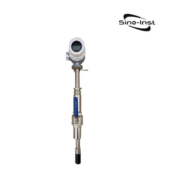
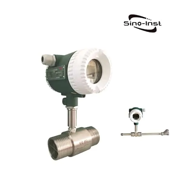
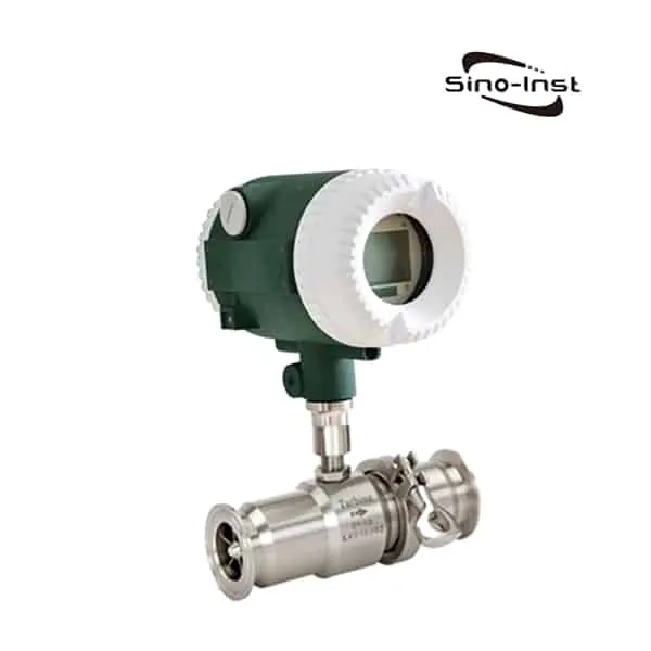
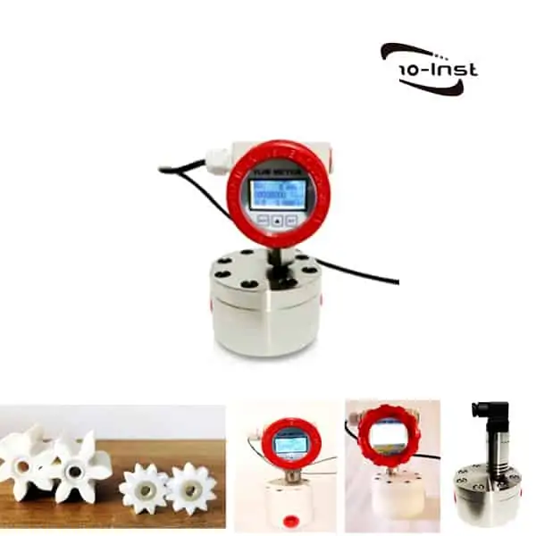
Liquid Turbine Flow Meter is a speed-type flow meter based on the principle of torque balance.
The fluid flows through the sensor housing. Because the blades of the impeller have a certain angle with the flow direction. The impulse of the fluid makes the blades have a rotational torque. After the friction torque and fluid resistance are overcome, the blades rotate. The speed is stable after the torque is balanced.
Under certain conditions, the speed is proportional to the flow rate.
Due to the magnetic permeability of the blade, it is in the magnetic field of the signal detector (composed of permanent magnets and coils). The rotating blade cuts the magnetic lines of force. The magnetic flux of the coil is periodically changed. Electrical pulse signals are induced at both ends of the coil.
This signal is amplified and reshaped by an amplifier. A continuous rectangular pulse wave with a certain amplitude is formed. It can be transmitted to the display instrument remotely. The instantaneous flow or total amount of the fluid is displayed.
Within a certain flow range, the pulse frequency f is proportional to the instantaneous flow Q of the fluid flowing through the sensor. The flow equation is:

Where:
f——Pulse frequency [Hz]
k——The meter coefficient of the sensor [1/m3], which is given by the calibration sheet.
Q——The instantaneous flow of fluid (under working condition) [m3/h]
3600-conversion factor in seconds
The meter coefficient of each sensor is filled in the verification certificate by the manufacturer. The k value is set in the matching display instrument. The instantaneous flow and cumulative total can be displayed.
Guess you like: What is Reynolds number?
Extended reading: Turbine Flow meter Vs Gear Flow meter
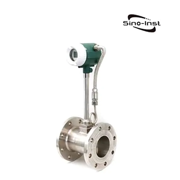
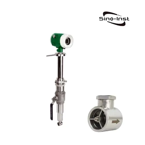
Vortex flowmeter is a speed-type flowmeter produced according to Karman’s vortex principle,
which can be used for the measurement and measurement of conventional gas, steam and
liquid.
Vortex flow sensor has high precision and wide range ratio, no moving parts in use, which can
improve mechanical stability and reduce maintenance. Vortex flowmeter is almost not affected by the temperature, pressure, and composition of medium when measuring the volume of working conditions.
Extended reading: High Pressure Rotameter for Liquids/gas-Upto 25 Mpa
Therefore, it is convenient to calibrate the instrument, so the vortex street flow sensor is widely used in production and life.
When a trigonal column vortex generator is set in the fluid, regular vortices are generated alternately on both sides of the vortex generator, which is called Carmen vortex.
The vortex columns are arranged asymmetrically downstream of the vortex generator. Vortex flowmeter is produced according to this principle.
Vortexes are generated by generating bodies and the number of vortexes is detected by high-sensitivity sensors. In a certain range, the number of vortexes generated is proportional to the flow rate.

In vortex flowmeter, the relationship between flow rate and the number of vortexes generated
can be expressed by the following formula:
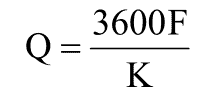
Q:Operating volume flow of the measured medium. The unit is m3/h。
F:Frequency of the number of vortices produced by the generating body. The unit is Hz.
K:Refers to the calculated or calibrated flow coefficient. It represents how many frequency signals per cube. the coefficient is usually obtained by calibration.
The formula of standard table method calibration coefficient K:
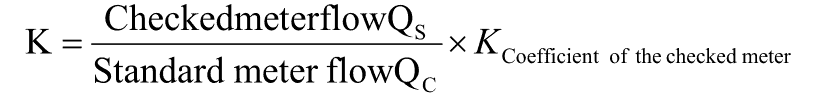
The formula can also be used for flow correction.
Extended Reading: Magnetic Battery Operated Flow Meter
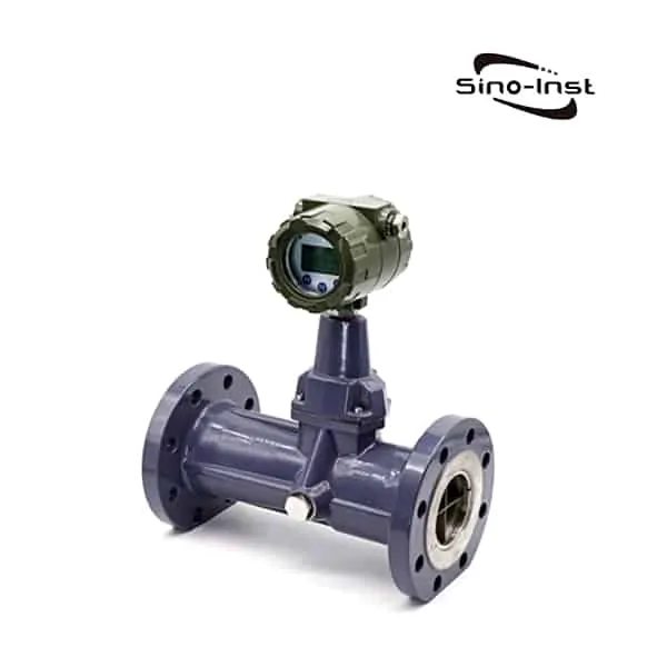
K coefficient of gear flow transmitter (flow coefficient) defines the number of impulses per L within the unit flow precisely.
The following formula is used:
Q=f×60/K
Q=Instantaneous flow L/min
F=Frequency of output impulse(HZ)
K= Coefficient of gear flow meter(impulse/min)
Read more General-purpose Flow Totalizer for Data collection and calculation

K-Factors calculation
1.What is a K-factor?
Simply stated a K-factor is a dividing factor. The term is usually encountered when dealing with pulse signals although analog K-factors are sometimes used.
2. Pulse Signal K-factors
All pulse output type flow meters when they are dispatched by their manufacturer will have a calibration certificate. The calibration certificate will show that the meter has been calibrated over its flow range and noted on the certificate will be the average K-factor for the meter.
This K-factor will be given in terms of the number of pulses produced by the meter for a given volumetric flow. (e.g.) 200 pulses per U.S. gallon, 150 pulses per liter, etc.
This K-factor is the value that is entered into a batch meter or indicator/totalizer in order to give a readout in engineering units.
Example 1
If the display on a rate meter is required in U.S. gallons per second, and the K-factor of the flow meter is 210 pulses per U.S. gallon, then the K-factor entered into the rate meter would be 210.
If a totalizer associated with the same flow meter was to be set up so as to totalize in U.S. gallons the totalizer K-factor would be 210.
If the totalizer was to be set to totalize in tenths of a gallon the K-factor would be 210/10 = 21
Example 2
If the display on a rate meter is required in U.S. gallons per minute, and the K-factor of the flowmeter is 210 pulses per U.S. gallon, then the K-factor entered into the rate meter would be: 210/60 = 3.5
3.K-factors for Analog Input Signals
When batching, indication or totalization has to be carried out using an analog input signal a KEP product first converts the 4 to 20 mA signal into a 0 to 10000 Hz. signal. The K-factor is then calculated by relating the engineering unit equivalent of 20 mA to the 10000 Hz. signal.
Extended Reading: Mechanical flow meter for diesel
Example 3
A vortex meter outputs 20 mA when the flow is 2000 U.S. gallons per minute, we wish to display the rate in gallons per minute.
The rate K-factor is = 10000/2000 = 5
The value of the totalizer K-factor will depend on whether the flow rate was given in units per second, a minute, or hour and whether it is desired to totalize in whole units, tenths, hundredths, etc.
If the flow rate was given in units per second the totalizer K-factor (for whole units) is obtained by multiplying the rate K-factor by 1.
If the flow rate was given in units per minute the totalizer K-factor (for whole units) is obtained by multiplying the rate K-factor by 60.
If the flow rate was given in units per hour the totalizer K-factor (for whole units) is obtained by multiplying the rate K-factor by 3600.
The totalizer K-factor in example 3 will be = 5 x 60 = 300 in order to totalize in gallons.
If we wished to totalize in tenths of a gallon the K-factor would be 5 x 60/10 = 30
Extended reading: rotameter applications
Example 4
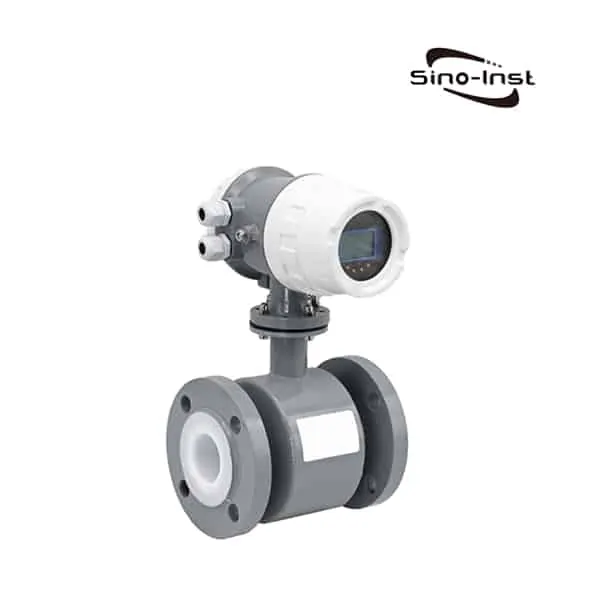
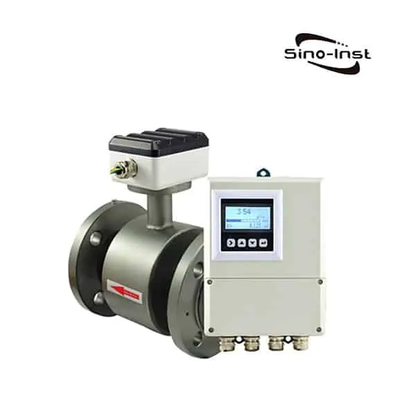
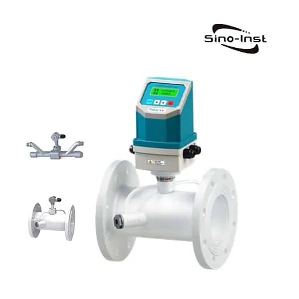
An electromagnetic flow meter outputs 20 mA when the flow is 20 liters per second, we wish to display the flow rate in liters per second and totalize in M³.
The rate K-factor is 10000/20 = 500
The totalizer K-factor will be 500 x 1/0.001 = 500000
Extended reading: Liquid Bitumen/Asphalt Flow Meter
4.Multi-Point K-factors
Some flow applications dictate that multiple K-factors are used. Two applications that require multiple K-factors are:
- flow meters with nonlinear outputs
- wide turndown flow applications
KEP meters have an option available that allows the user to input from 3 to 16 K-factors. This multi-point K-factor option is available for both pulse and analog inputs.
5.Multi-Point K-factors for Pulse inputs
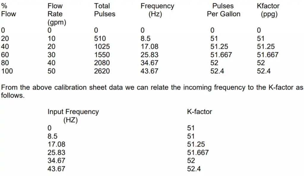
The first step is to calculate K-factors to cover each flow range. This is done by taking the information on the flow meter manufacturer’s calibration sheet and calculating the K-factors as per section 2. An alternative to using the manufacturers’ data is to conduct tests on-site against a calibrated standard.
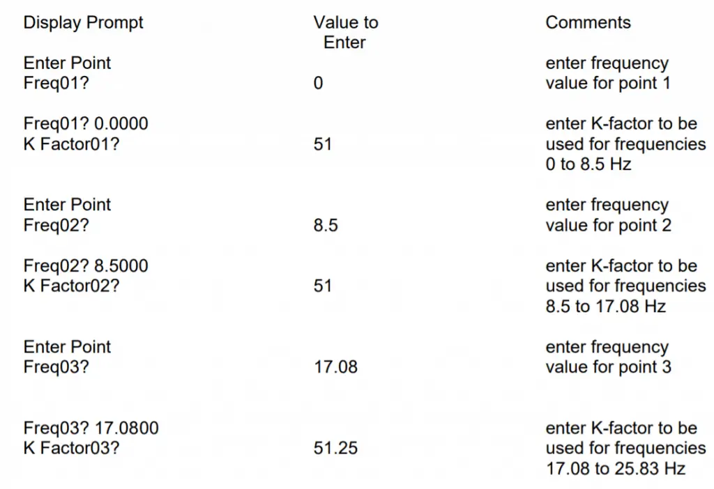
The second step is to relate an incoming frequency range from the flow meter to a given calculated K-factor.
The final step is to program these values into the KEP instrument.
Read more about: what is gpm;
Example 5
A turbine flow meter has the following calibration data.

Extended reading: Orifice Plate Flow Meter
6.Multi Point K-factors for Analog Inputs
The procedure for analog inputs is essentially the same as for pulse inputs.
The first step is to calculate K-factors to cover each flow range. This is done by taking the information on the flow meter manufacturer’s calibration sheet and calculating the K-factors as per section 3. An alternative to using the manufacturer’s data is to conduct tests on site against a calibrated standard.
The second step is to relate an incoming flow value from the flow meter to a given calculated K-factor.
The final step is to program these values into the KEP instrument.
Example 6
A vortex flowmeter has the following calibration data.
Base K-factor 10000/100 = 100


Note that the point after the final one should have a flow value entered that is very much higher than the true maximum flow rate of the meter. Note also that as the last two K-factors are the same any flow above 100 gpm will be modified by a K-factor of 104. The setup is now complete.
Extended reading: Flow Totalizer F3000X for Data collection and calculation
You may like:
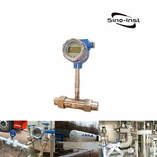
Sino-Inst offers over 50 flow meter for flow measurement. About 50% of these are differential pressure flow meters, 40% is the liquid flow sensor, and 20% are Ultrasonic flow Transmitter and mass flow meter.
A wide variety of flow meters options are available to you, such as free samples, paid samples.
Sino-Instrument is a globally recognized supplier and manufacturer of flow measurement instrumentation, located in China.

Wu Peng, born in 1980, is a highly respected and accomplished male engineer with extensive experience in the field of automation. With over 20 years of industry experience, Wu has made significant contributions to both academia and engineering projects.
Throughout his career, Wu Peng has participated in numerous national and international engineering projects. Some of his most notable projects include the development of an intelligent control system for oil refineries, the design of a cutting-edge distributed control system for petrochemical plants, and the optimization of control algorithms for natural gas pipelines.